Stark S-500 Guide

STARK®S-500
Installation, Operation & Maintenance Instructions
GENERAL NOTICE
The information provided in this document is very important and needs to be shared with everyone involved
in the installing, operating and the maintenance of the closure(s).
SAFETY NOTICE
Do not open the closure unless you are sure there is no pressure within the closure. All operators should
use the appropriate Personal Protective Equipment (PPE) and operating tools.
WELDING NOTICE
During welding, warpage can occur due to the heat generated. Please read sections 2.3, 2.4, & 2.5 for
recommendations to reduce warpage caused by welding. Excessive warpage will damage the product.
STARK® appreciates the support of all supervisors.
Should you have any questions or concerns not addressed in this document,
please contact us directly for assistance.
STARK® SOLUTIONS
10650 FM 1484 Rd.
Conroe,TX 77303
+1 936.539.2386
www.starksolutions.com
STARK® SOLUTIONS IS ASME “U” & “R” & ISO 9001-2015 CERTIFIED

2
Document No : CMM.0500.105 Rev :1
Version : 22.032
Table of Contents
Section 1: INTRODUCTION Page 03
Section 2: INSTALLATION Page 04
Section 2.1: Disassembly of Horizontal Hinge Closure Page 04
Section 2.2: Disassembly of Vertical Hinge Closure Page 05
Section 2.3: Attachment of Closure Page 06
Section 2.4: Installation of Closure Hub in the Field (Manual Welding) Page 06
Section 2.5: Installation of Closure Hub in Fabrication Shops (Automatic Welding) Page 06
Section 2.6: Sandblasting Page 07
Section 3: OPERATION Page 08
Section 2.1: Operation Instructions: Opening the Closure Page 09
Section 2.2: Operation Instructions: Closing the Closure Page 09
Section 2.3: First Time Start Up Page 09
Section 2.4: Proper adjustment of the Closure - Horizontal hinged closure Page 11
Section 2.5: Proper adjustment of the Closure - Vertical hinged closure Page 12
Section 2.6: Ready to Go Actions Page 12
Section 4: DISASSEMBLY & REASSEMBLY OF INSTALLED CLOSURE
Section 4.1: Horizontal Hinged Page 13
Section 4.2: Vertical Hinged Page 14
Section 5: MAINTENANCE INSTRUCTIONS Page 15
Section 5.1: General Maintenance Page 15
Section 5.2: Inspection Page 15
Section 6: REFERENCE DRAWINGS Page 16

3
Document No : CMM.0500.105 Rev : 1
Version : 22.032
S-500 Closure 2” through 52” Instructions for Installation,
Operation & Maintenance
Section 1: INTRODUCTION
The S-500 IS Stark’s Threaded Closure, manufactured in diameters
ranging from 2” to 52” (DN50 to DN1300) and pressure series 150
through 2500. Closures are equipped with a Pressure Alert Valve
(PAV) which warns the operator of possible residual pressure. The
PAV must be removed from the hub to rotate the cap in
compliance with ASME SEC VIII DIV. 1 UG 35, providing another
step in ensuring safety.
Opening tools are supplied to assist in breaking the closures seal
and prevent unnecessary hammering of the closure cap lugs. On 6”
to 14” closures, lug wrenches are provided which deliver optimal
leverage for the operator based on the strategic placement of Figure 1. S-500 Threaded Closure
the closure’s lugs. Should you not have the Stark provided lug
wrench, the S-500 was designed with a square boss located at the center of the cap on sizes 2” to
14”, which allows the use of a standard wrench. Closures 16” and larger are equipped with a
ratchet tool that attaches to the hinge base on the hub, and ratchet tool lugs on the cap. In
addition to opening tools, new ways to make this proven closure style even more user friendly
were incorporated by including a double roller hinge design on horizontal closure sizes 16” and
larger, and an integrated bearing in the hinge rollers on sizes 24” and larger. These features provide
further guidance for the cap, which improves the control and ease of operation.
The threaded closure design aids in the compression of the O-ring. The cap threads rotate and
tighten down within the hub threads. Once fully tightened, there is metal to metal contact of the
cap and hub’s flat sealing surfaces; this means the O-ring groove is fully sealed for optimal O-ring
performance. The use of an industry standard O-ring makes replacement parts readily available and
cost efficient.

4
Document No : CMM.0500.105 Rev :1
Version : 22.032
Section 2: INSTALLATION
Section 2.1 Disassembly of Horizontal Hinge Closure, not Installed
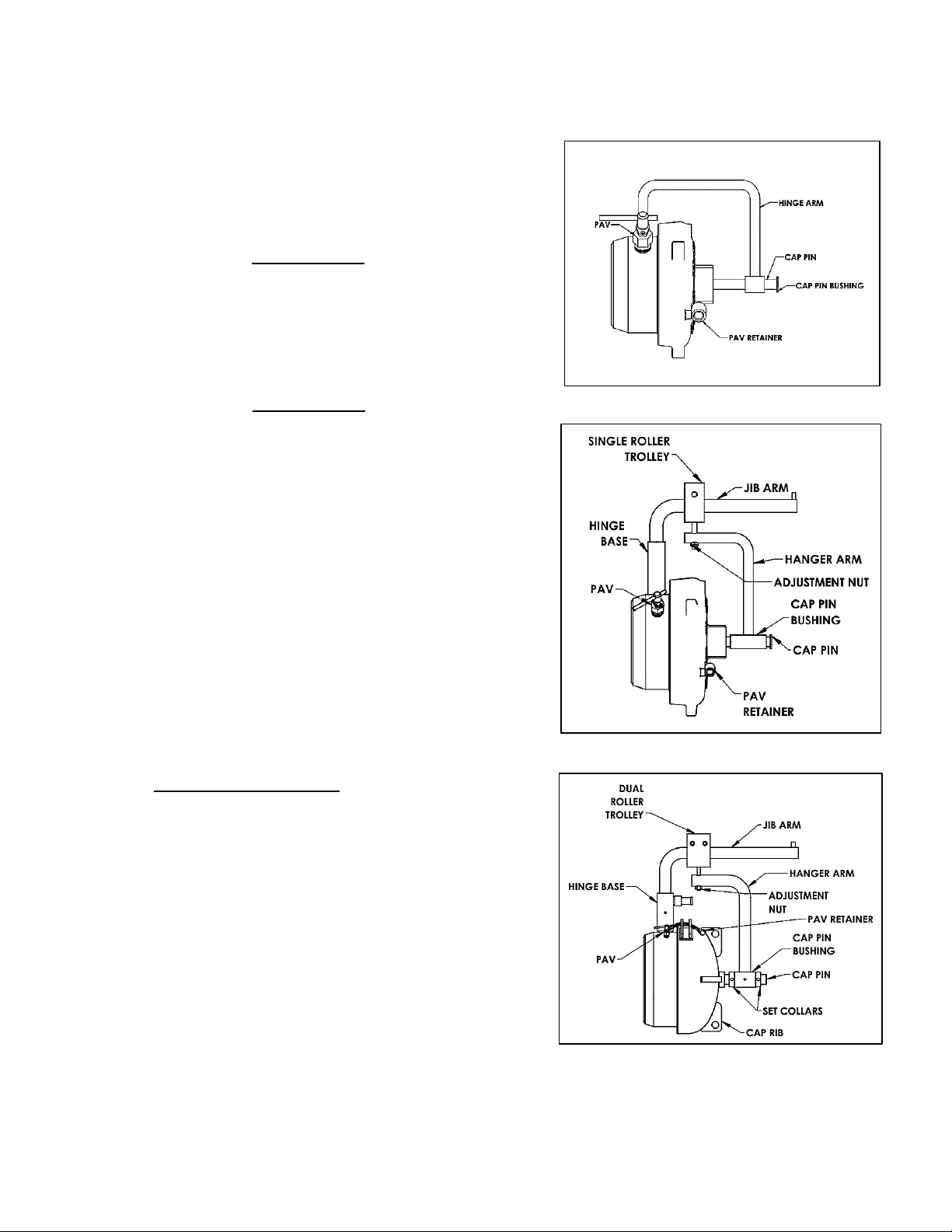
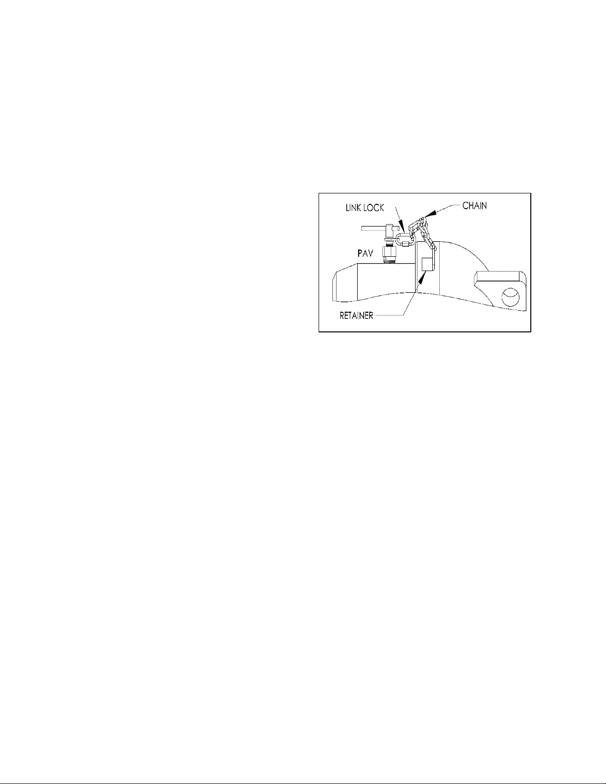
A. If a Pressure Alert Valve (PAV) is present, remove the
stem and screw it into the retainer on the cap. The
PAV is standard on all closures 6” and larger;
optional on sizes 2”, 3”, and 4”.
On closures 14” and under, unscrew the cap from
the hub and lift the attached hinge components
from the hinge base. A cotter pin may need to be
removed from the hinge arm to accomplish this on
some sizes.
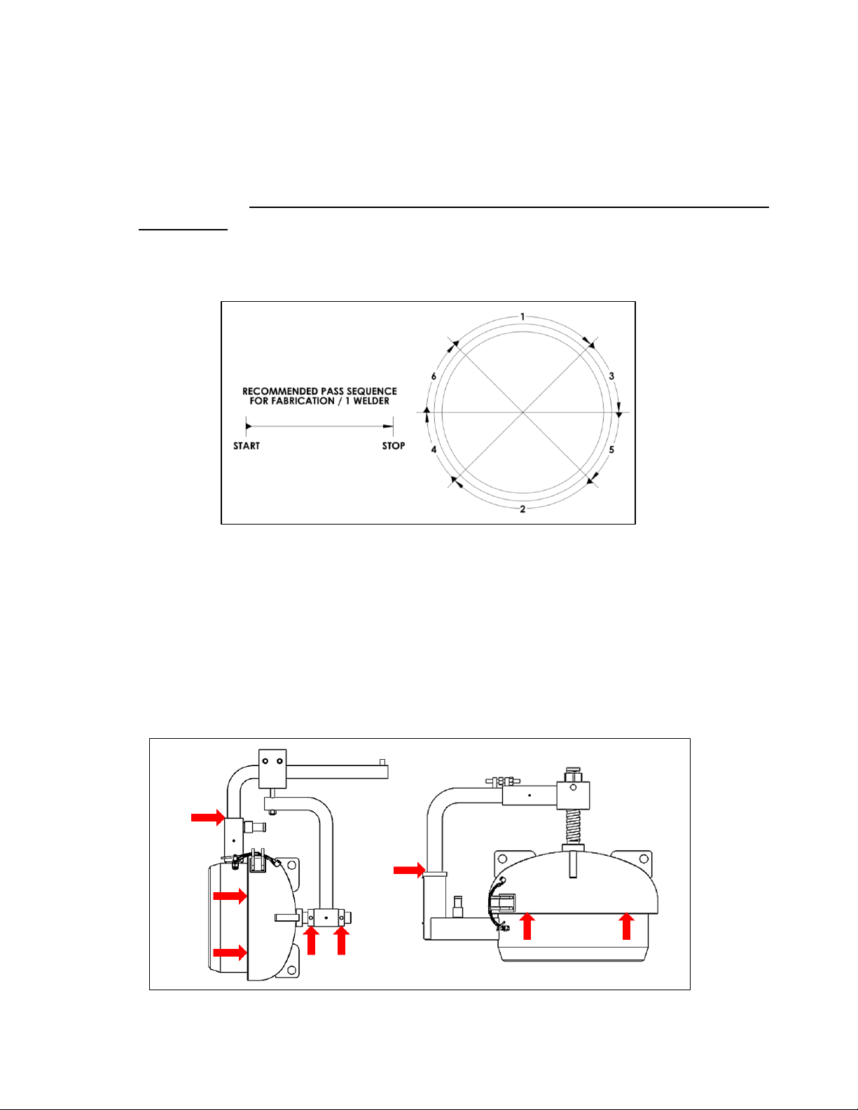
B. On closures 16” and larger, remove the outer set
collar from the cap pin and remove the hanger arm
from the cap pin. Leave the inner set collar in place,
this will retain the cap balance location set by the
manufacturer. On 30” SERIES 600 and larger
closures the cap pin bushing has roller bearings
inside. Make sure the cap pin is free of all burrs to
ease removal of the inner bearing race. Store
bearings with care and keep them protected from
dust, grit, and other contaminants.
NOTE: A burr may be left behind by the set screw in the
collar. Using a file or emery cloth, remove the burr prior
to removal of the hanger arm and/or related
components.
D. 16” and larger closure are equipped with a dual
roller or wheel trolley. Measure the distance from
the bottom of the jib arm to the top of the hanger
arm or put a reference mark on the adjustment bolt
above the hanger arm. Remove the nut, V-block on
24” SERIES 600 and larger, and hanger arm from the
closure. Do not remove the trolley from the jib arm.
E. Remove the jib arm from the hinge base. The jib
assembly of 24” SERIES 600 and larger closures are
equipped with a brass bushing and tapered roller
(Figure 2) 2” to 4” Closure (hinged)
(Figure 3) 6” to 14” Closure
(Figure 4) 16” to 24” SERIES 300

5
Document No : CMM.0500.105 Rev :1
Version : 22.032
bearing inside the hinge base. Take care not to
damage these components. Remove the tapered
bearing race (steel cup) from the bottom of the
hinge base.
F. Attach a hook sling to at least three cap ribs. Use
the supplied opening tool to break the seal and
loosen the cap if necessary. Using a crane,
continue to unscrew the cap using just enough
lift
G. to keep the cap floating between threads. Keep
lifting and turning until the cap clears the hub.
Place the cap face down on a clean, flat surface.
Plywood or a wooden pallet is preferred. (Figure 5) 24” SERIES 600 to 30” SERIES 300
300
(Figure 6)30” SERIES 600 to 52”

6
Document No : CMM.0500.105 Rev :1
Version : 22.032
(Figure 7) 2” to -4” Closure (hinged)
Section 2.2: Disassembly of Vertical Hinge Closure, not Installed
A. Locate the Pressure Alert Valve (PAV), remove the stem
and screw it into the retainer on the cap. The PAV is
standard on all closures 6” and larger; optional on sizes
2”, 3”, and 4”.
B. On closures 14” and under, unscrew the cap from the
hub. Lift the cap with attached hinge components out of
the davit base.
IMPORTANT: Keep the cap centered over the hub at this time.
Swinging the cap to the side will cause a weight imbalance
and the closure may fall over causing injuries and equipment
damage.
C. On 16” and larger closures, use the supplied ratchet
tool to break the seal, then unscrew the cap.
IMPORTANT: Keep the cap centered over the hub at this
time. Swinging the cap to the side will cause a weight
imbalance and the closure may fall over causing injuries and
equipment damage.
D. Using a hook sling on at least 3 cap rips and lift the
cap with its hinge components out of the davit base.
Support the davit arm also if needed.
E. 24” SERIES 600 and larger closures are equipped with
a bronze bushing and tapered roller bearing inside
the davit base. Take care not to damage these
components. Remove the tapered bearing race
(steel cup) from the bottom of the davit base. Place
cap face down on a clean flat surface allowing the
arm to hang freely. Stacked wooden pallets are
preferred.
(Figure 8) 6” to 14” Closure
(Figure 9) 16” to 24” SERIES 300
(Figure 10)24” 600 to 52”

7
Document No : CMM.0500.105 Rev :1
Version : 22.032
Section 2.3: Attachment of the Closure
Important: All welding should be performed by qualified welders in accordance with qualified
procedures. To avoid hub warpage, complete all nozzle and attachment welds prior to the closure
installation!
Section 2.4 For Closure Hub in the Field (Manual Welding)
A. Remove the PAV, o-ring, and cap from the closure hub. Remove the hinge components as
referred to in Section 2.1 or 2.2.
B. Fit the hub to the vessel. The use of internal or “spider” bracing is recommended, especially
with thinner wall thicknesses.
•No hinge closures shall be fit with the PAV in the 12 o’clock position on horizontal
applications.
•Hinged closures shall be fit with the hinge base level vertically.
C. Weld root and hot passes. The amount of heat should be minimized to avoid possible hub
sealing surface warpage. Using two welders on opposite sides of the closure to reduce the
amount of residual stress induced is highly recommended on sizes 16” and larger. A
recommended pass sequence is illustrated on the top of the page.
D. Replace the PAV and reassemble the closure. Make any necessary adjustments. Reference
the horizontal or vertical adjustment section of this Manual for proper adjustment
procedures.
Section 2.5 For Closure Hub in the Fabrication Shops (Automatic Welding)
A. Remove the PAV, o-ring, and cap from the closure hub. Remove the hinge components as
referred to in Section 2.1 or 2.2.
B. Fit the hub to the vessel. The use of internal or “spider” bracing is recommended, especially
with thinner wall thicknesses.
•No hinge closures shall be fit with the PAV in the 12 o’clock position on horizontal
applications.
Figure 11. Weld Map (Field)

8
Document No : CMM.0500.105 Rev :1
Version : 22.032
•Hinged closures shall be fit with the hinge base level vertically.
C. Weld the root pass. A recommended pass sequence is illustrated on the top of the page.
D. Complete the hub to vessel weld using care to minimize heat build up to avoid possible
warpage of the hub seal face.
E. Before post weld heat treatment, remove all grease from the hub threads. A coating of an
anti-splatter product used for welding will protect against scale build up during the post weld
heat treatment. DO NOT PERFORM POST WELD HEAT TREATMENT ON HINGE COMPONENTS
OR THE CAP!
F. Replace the PAV and reassemble the closure. Make any necessary adjustments. Reference
Section 3.4 or 3.5 for proper adjustment procedures.
Section 2.6 Sandblasting Precautions
A. Mask all critical areas (Figure 13), with suitable masking material. Duct tape is often effective,
your experience may vary.
B. Avoid sandblasting directly towards the masked areas.
C. Thoroughly clean the thread, seal, and moving part areas after sandblasting.
Figure 12. Weld Map (Fabrication Shop)
Figure 13. Critical Areas

9
Document No : CMM.0500.105 Rev :1
Version : 22.032
Section 3: OPERATION
Section 3.1 Opening the S-500 Closure
IMPORTANT: Make certain all pressure has been safely bled from the vessel or pipeline section.
Attempting to open a closure without doing so could lead to a violent expulsion of pressure resulting
in injury or death.
A. Remove the Pressure Alert Valve (PAV) stem, if so equipped, and screw it into the retainer on
the cap. The PAV is used to alert the operator of residual pressure in the vessel or pipeline.
Unrelieved pressure can cause severe injury
or death. If residual pressure is indicated,
replace the PAV stem and ensure the vessel
or pipeline is bled of all pressure. Do NOT
use the PAV to bleed pressure from the
vessel.
NOTE: The Pressure Alert Valve (PAV) is standard
on all closure 6” and above. The PAV is optional
on 2” to 4” non-ASME code stamped closures.
.
B. Rotate the cap counterclockwise with the pipe wrench (Figure 15), Stark provided lug wrench
(Figure 16) or Stark provided Closure Actuation (CAT) tool (Figure 17) until cap can be turned
by hand. Do not use a hammer to open the cap. Hammering will deform the lugs on the cap
and possibly lead to cracking of the cap or injuries.
C. Rotate the cap until it is free of the hub. Then swing the cap to the side to gain access to the
vessel or pipeline.
IMPORTANT: For the safety of the operator and other crew members, stand to the side of the closure
when opening the cap. Do not stand directly in front of the closure when opening.
Figure 14. PAV

10
Document No : CMM.0500.105 Rev :1
0 Version : 22.032
Section 3.2 Closing the S-500 Closure
Align the cap to the hub and rotate clockwise. Tighten the cap with a lug wrench or ratchet tool until
your reference marks line up. The reference marks indicate a metal-to-metal contact of the cap and
hub sealing surface.
NOTE: On closures with a PAV, replace and tighten the PAV stem into the PAV body hand tight. Do
not use tools to tighten the PAV, damage to the PAV may result.
Figure 15. Standard Pipe Wrench
Figure 16. Lug Wrench (6” to 14”)
Figure 17. CAT tool (16” to 52”)
Figure 18. S-500 Opening Tools

11
Document No : CMM.0500.105 Rev :1
Version : 22.032
Section 3.3 First Time –Start up
A. Open the closure as shown in the Section 3.1, “Opening the S-500 Closure”.
B. With the closure open, remove the O-ring and clean the sealing surfaces of the cap and hub
removing all grease and debris.
C. Apply a thin film of clean grease to the sealing surface of the cap. Carefully close the cap until
it makes solid contact with the hub. Use caution to avoid over tightening or unnecessary
force when mating the cap to the hub. The sealing surface of the hub and cap should now
have metal to metal contact and cannot be tightened further. At this point, make permanent
alignment marks on the cap and hub for future reference.
D. Remove cap from hub and check for a clean and consistent transfer of grease from the sealing
face of the cap to the hub.
E. After verifying the condition of the closure and o-ring as described in “Section 3 Maintenance
Instructions”, place the o-ring into the o-ring groove and make sure it is seated fully and not
twisted. Apply lubricant to the threads and seal area of the closure. Use anti-galling lubricant,
like light to medium lithium grease. Do not use silicone type grease!
F. Close the cap until the alignment marks on the cap and hub return to their original positions.
Use your pipe wrench, lug wrench or ratchet tool, if necessary, to compress the o-ring. The
closure should now have metal to metal contact between cap and hub with the o-ring in the
groove and fully sealed. Take care not to over tighten the closure after all relative motion
stops, or your reference marks line up. Overtightening may result in damage to the closure
or tightening tool.
Section 3.4 Proper adjustment of the Closure - Horizontal hinged closure
A. 2”to 4” Horizontal Hinged closure: These closures are manufactured with no
adjustment mechanism. No adjustment is necessary.
B. Horizontal hinge closures 6”through 14”:Center the cap to hub using the vertical
adjustment nut below the hinge arm.
C. Horizontal closures 16” and larger:
•Vertical adjustment to center the cap to the hub is made by turning the adjustment
nut located under the trolley assembly.
•Position the cap close to the hub to inspect parallel alignment. Adjustments are made
by moving the hanger arm in or out along the cap pin.
IMPORTANT: Parallel Adjustment must be made with the cap threaded on to the hub! Otherwise,
the cap may fall when the set collars are loosened.
If the cap is closer at the top of the hub, loosen the inside set collar (closure must be closed)
and move the hanger arm in towards the cap. When parallel alignment has been achieved
move the outer set collar in towards the cap accordingly. If the cap is closer at the bottom of
the hub, loosen the outer set collar (closure must be closed) and move the hanger arm away
from the cap. When parallel alignment has been achieved move the inner set collar away
from the cap accordingly and tighten both set collars. Never leave the outer set collar loose!

12
Document No : CMM.0500.105 Rev :1
Version : 22.032
Note: Set collars may leave a bur on the cap pin due to the set screw in the collar. Remove the bur
with a file or emery cloth to ease movement of the hanger arm.
Section 3.5 Proper adjustment of the Closure - Vertical hinged closure
A. 2” to 8” closures: These closures are manufactured with no adjustment mechanism.
No adjustment is necessary.
B. 10” to 24” SERIES 300: The cap should screw on to the hub with little to no thread drag.
Use the adjustment bolt located in the bottom of the davit base to lift or lower the
cap to eliminate contact between the two components.
C. 24” SERIES 600 and larger: These closures feature both lateral and vertical adjustment
Lateral Adjustment:
Center the cap with the hub with the adjuster located on top of the davit arm
adjustment sleeve. Be sure to tighten both sides of the adjuster when complete.
Vertical Adjustment:
Loosen the set screw in the pivot box assembly. Turn the vertical adjustment nut
clockwise to raise the cap and counterclockwise to lower the cap. Tighten the set
screw after adjustments when checking the operation of the closure. Make only small
adjustments and repeat as necessary to obtain minimal thread drag.
Section 3.6 Ready to go Actions
Before delivery to the end user or storage plans, ensure the closure is ready for reliable service in
the field. During final make-ready, grease all grease zerks until grease flows from the joint, then wipe
away excess. The closure should operate with little to no thread drag. Operate the closure, if
resistance or thread drag is felt, see Section 3.4 or 3.5 for proper adjustment procedure. Keep the
cat tool or lug wrench with their respective closures.

13
Document No : CMM.0500.105 Rev :1
Version : 22.032
Section 4: DISASSEMBLY & REASSEMBLY OF INSTALLED CLOSURE
Section 4.1 Disassembly and reassembly of an installed closure- Horizontal
Disassembly
Locate the Pressure Alert Valve (PAV), remove the stem and screw it into the PAV retainer on the
cap. The PAV is standard on all closures 6” and larger. Never attempt to open the closure while
under pressure!
Closures 6” to 14”:
Open the closure reference Section 3.1. While supporting the cap to prevent it from falling freely,
remove the adjustment nut from the trolley assembly and safely lower the cap away from the
closure. Lift the hinge components out of the base.
Closures 16” to 48”:
Determine if the service to be performed requires opening the closure. The closure hinge
components may be removed without opening the closure.
•If the closure can remain closed, remove the outer set collar from the cap pin and slide the
hanger arm away from the cap pin. Leave the inner set collar in place, this will retain the
parallel balance set by the manufacturer.
•Remove the vertical adjustment nut from the trolley assembly and safely lower the hanger
arm off the trolley.
•Lift the hinge components from the hinge base.
•If the closure needs to be open, reference Section 3.1.
•Mark the position of the vertical adjustment nut. Place a lifting strap near the bend of the
hanger arm. Make sure the set collars on the cap pin are secured. Lift slightly the cap and
hanger arm together to facilitate removal of the vertical adjustment nut.
•Remove the vertical adjustment nut and lower the cap and jib arm until they clear the trolley
assembly.
•Place the cap on a flat clean surface. Plywood or wooden pallets are preferred.
•Lift the hinge components from the hinge base. If the closure is equipped with a dual roller
or wheel trolley, do not remove them from the jib arm.
NOTE: Closures 24” SERIES 600 and up are equipped with a tapered roller bearing and a brass bushing
on the jib post. Do not to damage these components during handling.
Assembly
NOTE: Prior closing the closure follow Section 3: Maintenance.
•Insert the jib arm and trolley assembly into the hinge base.
•If the cap was left on the closure, lift the hanger arm onto the trolley assembly and replace
the saddle block (24” SERIES 600 and up) and vertical adjustment nut.
•If the cap was removed, lift the cap and hinge arm onto the trolley assembly and replace the
saddle block (24” SERIES 600 and up) and vertical adjustment nut.
•Adjust the closure for proper operation, reference Section 3.4.

14
Document No : CMM.0500.105 Rev :1
Version : 22.032
•Replace and tighten cap, reference Section 3.2, replace the PAV stem into the PAV body and
return the unit to service.
Section 4.3 Disassembly and reassembly of an installed closure- Vertical
Disassembly
Locate the Pressure Alert Valve (PAV), remove the stem and screw it into the retainer on the cap.
The PAV is standard on all closures 6” and larger. Never attempt to open the closure while under
pressure!
Closures 6” to 14”:
Unscrew the cap until the cap pin bottoms out on the cap pin bushing. Lift the hinge components
with the cap from the base.
Closures 16” to 24” SERIES 300:
Unscrew the cap until the cap pin bottoms out on the cap pin bushing. Attach a sling to a minimum
of three cap ribs. Carefully lift the assembly until the davit arm is free of the base.
Closures 24” SERIES 600 and larger:
Unscrew the cap until the cap pin bottoms out on the cap pin bushing. Attach a sling to a minimum
of three cap ribs. Carefully lift the assembly until the davit arm clears the base.
NOTE: Make sure not to damage the tapered roller bearing and brass bushing on the davit arm during
the handling. Place the cap face down on aclean level surface. Plywood or wooden pallets are
preferred.
Assembly
NOTE: Follow the Section 5: Maintenance prior closing the closure.
6” to 14” closures:
Insert Davit arm into base until fully seated. Screw the cap on. Replace the PAV stem into the
PAV body.
16” to 24” SERIES 300:
Insert davit arm into the base until fully seated. While closing the cap verify proper vertical
adjustment (reference section vertical adjustment). Replace the PAV stem into the PAV body.
24” SERIES 600 and larger:
Insert davit arm into the base. While screwing the cap onto the hub verify proper vertical
and horizontal adjustment. The cap should screw down with no thread drag. If noticeable
resistance is felt adjust the closure. Reference Section: Proper Adjustment of the Closure.

15
Document No : CMM.0500.105 Rev :1
Version : 22.032
Section 5: MAINTENANCE & INSPECTION
Section 5.1 Maintenance Instructions
Every time your Stark S-500 closure is opened, visually inspect the closure to ensure trouble free
reliable service:
A. Clean the closure threads, sealing surface, o-ring and o-ring groove. Remove grease and any
debris from hub and inside the cap.
B. If any cracks are found in the cap or hub, discontinue use, and replace the component.
C. Lubricate threads, sealing surface, cap pin bushing and hinge base. Lubricate the o-ring
groove with a thin film of grease, just enough to support the o-ring to sink into the o-ring
groove smoothly. Use anti-galling lubricant, like light to medium lithium grease. Do not use
silicone type grease.
D. If adjustment to the vertical or horizontal hinge is needed, reference Section 3.4 & 3.5,
“Proper adjustment of the Closure”.
Section 5.2 Inspection of the condition of the closure
A. Inspect the O-ring for rough surfaces, nicks, or cuts. If any defects are found, replace it with
an O-ring from Stark to ensure the dimensional integrity. Clean new or re-used o-rings,
lubricate them lightly and place them in the O-ring groove.
B. Procedure for thread inspection:
Find the thread profile that matches the
threads on your closure and snugly insert
the gauge. Inspect both the cap and hub
for:
•Galling, Gouges, or nicks
•Excessive wear/corrosion
•Worn thread flanks
•Rounded thread crests
•Deformed thread profiles
•Cracks, especially at the thread
root.
•Check the closure in at least four places on cap and hub. 12:00, 3:00, 6:00 & 9:00
positions are recommended
NOTE: A thread gauge (Figure 19) is available from Stark. It is a template with the three thread
profiles used on Stark closures. The gauge allows the user to evaluate thread wear based on a
visual comparison of the thread form between the gauge and the closure component.
Figure 19. Thread Gauge

16
Document No : CMM.0500.105 Rev :1
Version : 22.032
Section 6: REFERENCE DRAWINGS
S-500 Horizontal
2” to 4”
6” to 14”
16” to 24” SERIES 300 24” SERIES 600 to 30” SERIES 300
30” SERIES 600 to 52”

17
Document No : CMM.0500.105 Rev :1
Version : 22.032
S-500 Vertical
2” to 4” VERTICAL 6” to 8” VERTICAL
10” to 14” VERTICAL 16” to 24” SERIES 300 VERTICAL
24” SERIES 600 to–52” VERTICAL
Table of contents
Other Stark Industrial Equipment manuals

Stark
Stark S-3000 Guide

Stark
Stark 67001 User manual

Stark
Stark 65027 Original instruction manual

Stark
Stark S-2000 Guide

Stark
Stark TL 7500 Operating instructions

Stark
Stark 5030 Operating instructions

Stark
Stark 75140 Original instruction manual

Stark
Stark 66012 Original instruction manual

Stark
Stark 61041 User manual

Stark
Stark RF 900 Operating instructions