TER Romeo User manual

Romeo
Romeo
Joystick
stepped or stepless
b u s i n e s s
business
p a r t n e r
partner
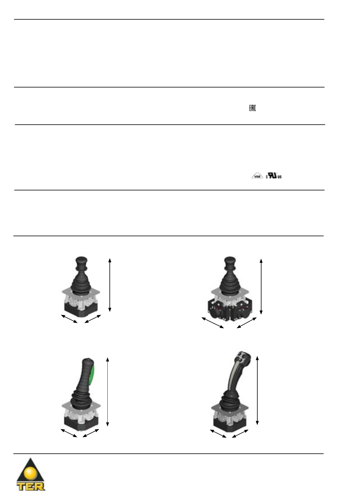
Romeo is a joystick designed to control complex machine
tools used in heavy duty and aggressive environments.
Design
Design
Materials, technical solutions and size and shape of critical
components ensure mechanical strength and life, and
special attention is paid to design, ergonomics, sensitivity
and accuracy of operation.
Options
Options
Three different versions of Romeo are available: with
free movement, with “dead man” safety device (with
mechanical interlock with or without NO/NC contact), or
with electrical interlock. Not all versions are available on
any handle of Romeo.
The movement of the rod in both directions can be
configured by means of the lever guides. Romeo is a
small size joystick available with up to 6 speeds, with or
without potentiometer or encoder; a stepless version also
available, with integrated analogical actuator, and with
current, voltage or PWM outputs.
Materials
Materials
Structural components are made of die-cast nickel-plated
zama to ensure maximum resistance, while parts subject
to wear are made of techno-polymer.
02042013-01
Construction
lifting
Industrial
lifting
Stage
technology
Industrial
automation
TER Tecno Elettrica Ravasi srl
Via Garibaldi 29/31 - 23885 Calco (LC) - Italy
Registered Office - via San Vigilio 2 - 23887 Olgiate Molgora (LC) - Italy
www.terworld.com
The data and the products illustrated in this brochure may be modified without notice. Under no circumstances can their description have a contractual value.
Standards - Markings - homologations
Standards - Markings - homologations
- Conformity to Community Directives:
2006/95/CE: Low Voltage Directive
2006/42/CE: Machinery Directive
- Conformity to Standards:
EN 60204-1 Safety of machinery - Electrical equipment of machines
EN 60947-1 Low-voltage switchgear and controlgear
EN 60947-5-1 Low-voltage switchgear and controlgear - Control
circuit devices and switching elements - Electromechanical control
circuit devices
EN 61000-6-2 Electromagnetic compatibility (EMC) - Generic standards
- Immunity for industrial environments
EN 61000-6-3 Electromagnetic compatibility (EMC) - Generic standards
- Emission standard for residential, commercial and light-industrial
environments
- Markings and homologations: C
16092014-02
- Storage ambient temperature: -40°C/+70°C
- Operational ambient temperature: -25°C/+70°C
- Protection degree: IP 00 (IP 65 max. when assembled in specific enclosure)
- Insulation category: Class I
- Operating positions: any position
- Markings and homologations: C
General technical specifications
General technical specifications
- Utilisation category: AC 15
- Rated operational current: 2 A
- Rated operational voltage: 48 V~
- Other operating electrical usage:
125 VAC / 1 A
250 VAC / 0,5 A
30 VDC / 1 A
- Rated thermal current: 8 A
- Rated insulation voltage: 60 V~
- Mechanical life: 0.5x10⁶operations
- Connections: terminal board
- Wires: 0.2 mm2- 2.5 mm2
- Tightening torque: 0.5 Nm - 0.6 Nm
- Markings and homologations: Cc
Technical specifications of the microswitches
Technical specifications of the microswitches
- Supply voltage: 12 ÷ 48 V AC/DC
- Proportional outputs:
2 voltage outputs: 0 ÷ +10 Vdc
2 current outputs: 4 ÷ 20mA
2 PWM outputs: 0 ÷100% (freq=1KHz)
- Resolution: 10 bit
- 4 directional microswitches: max 2A / 48V
- Screw terminals: 2.5 mm2(max. section)
Technical specifications of stepless joystick
Technical specifications of stepless joystick
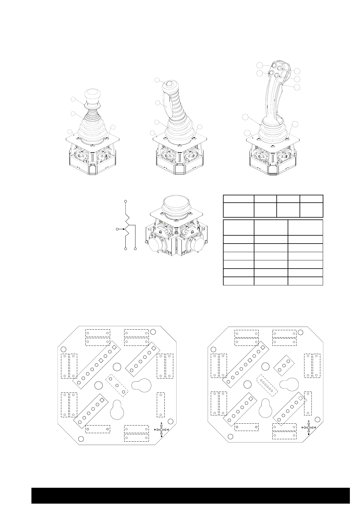
Overall dimensions
Overall dimensions
With standard knob and
potentiometers
With standard knob
216 mm
100 mm100 mm
216 mm
131 mm
131 mm
With handle with NO contact
and pushbutton
257 mm
100 mm
100 mm
281 mm
100 mm100 mm
With ergonomic handle
R o m e o -
Romeo -
J o y s t i c k
Joystick
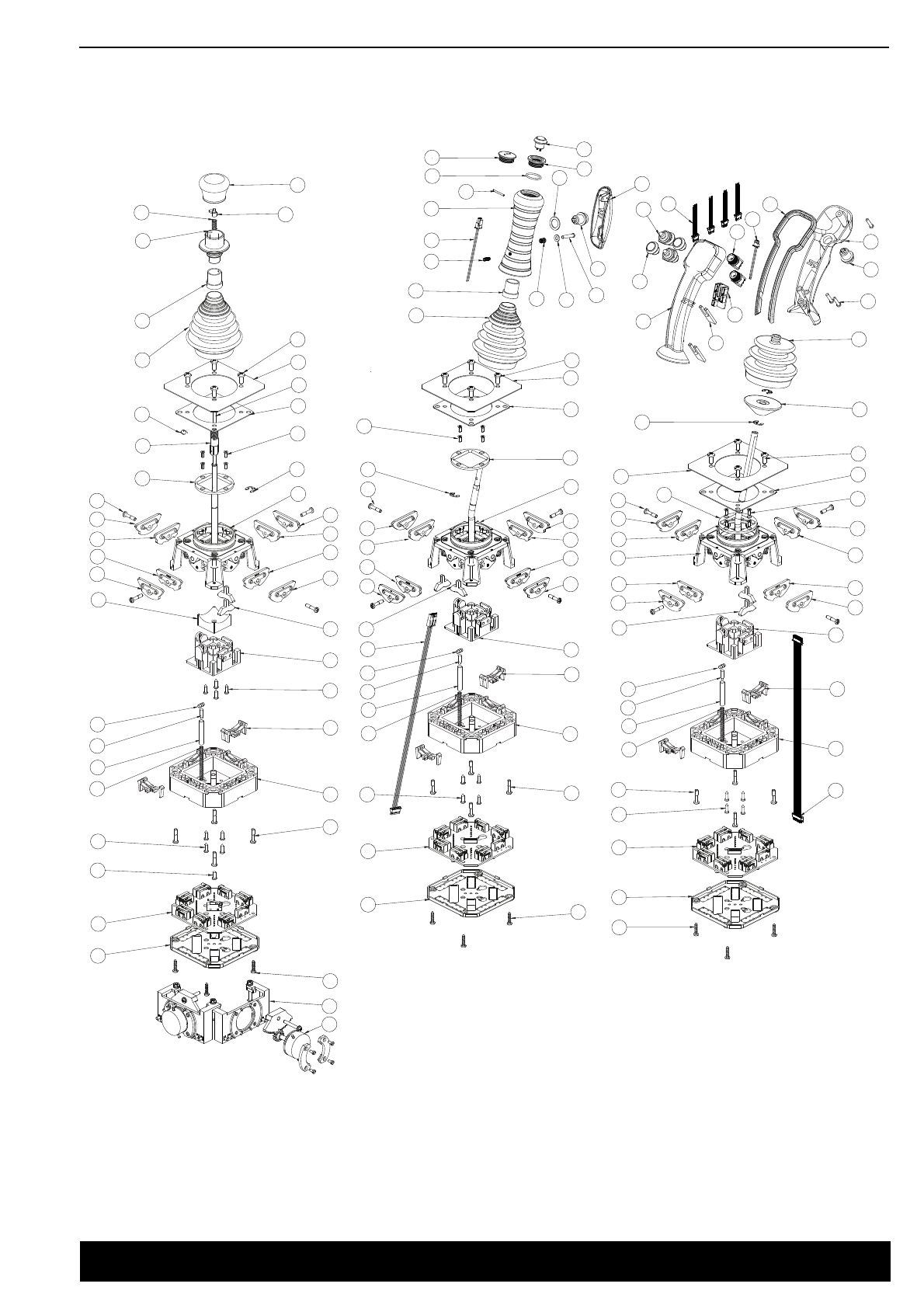
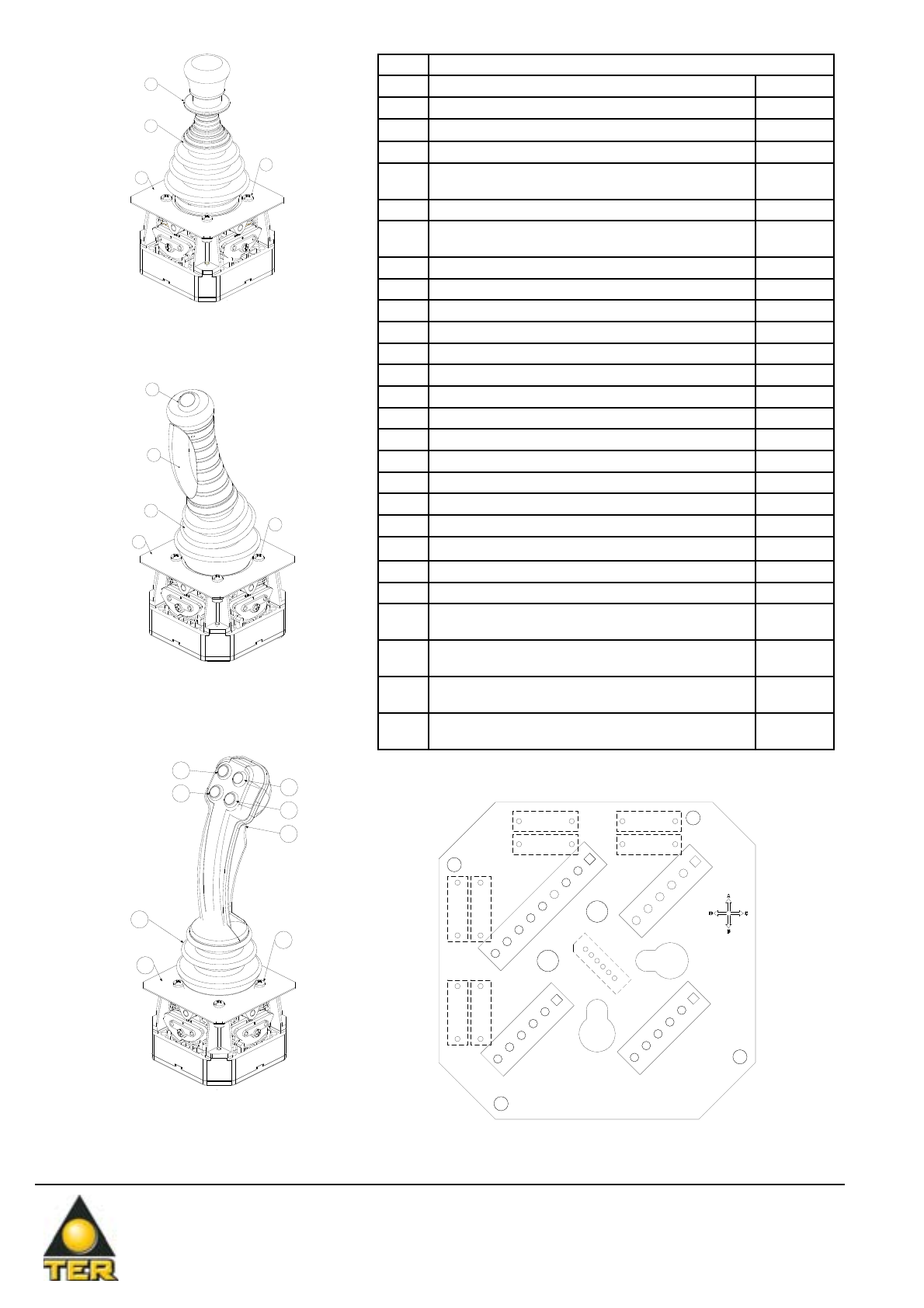
Detailed drawing
Detailed drawing
16
45
19 22
8
1
2
3
4
5
6
7
9
11
12
14
16
17
18
19
37
35
34
33
32
31
30
29
27
28
26
24
8
22
10
27
28
10
8
9
13
15 23
25
12
13
14
15 23
24
44
31
8
30
7
28
27
27
28
26
9
10
9
10
32
34
35
21
20
46
25
10
9
26
8
16
45
19
22
27
28
12
13
14
15 23
24
25
53
56
30
34
7
57
8
9
10
58
28
27
31
32
35
59
60
61
50
62
63
65
64
55 67
42
66
38
39
42
4
3
40
41
50
47
43
49
52
48
51
53
54
16
36
02042013-03
TER Tecno Elettrica Ravasi srl
Via Garibaldi 29/31 - 23885 Calco (LC) - Italy
Registered Office - via San Vigilio 2 - 23887 Olgiate Molgora (LC) - Italy
www.terworld.com
The data and the products illustrated in this brochure may be modified without notice. Under no circumstances can their description have a contractual value.
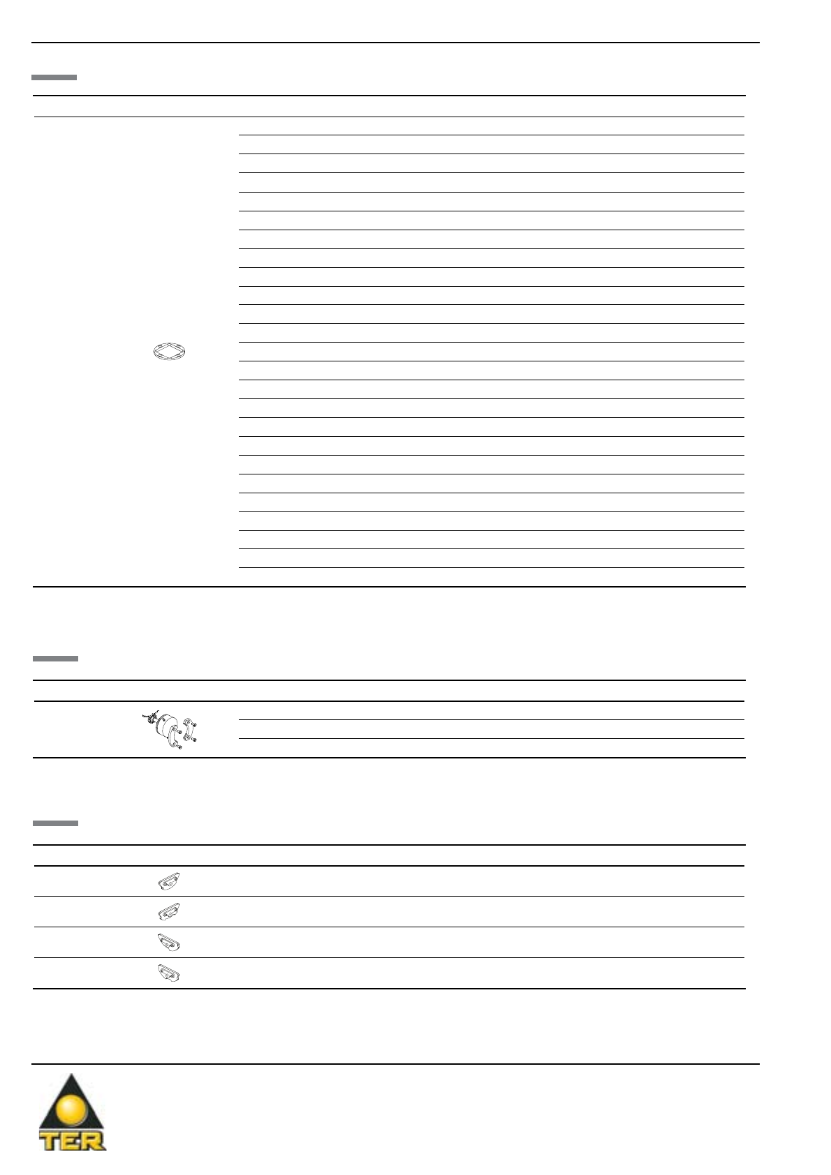
Components
Components
02042013-04
Potentiometers
Potentiometers
Ref Drawing Description Code
20
Potentiometer Megatron 2.2 kΩPRVV9035PE
Potentiometer Megatron 4.7 kΩPRVV9020PE
Potentiometer Megatron 10 kΩPRVV9025PE
Lever guides
Lever guides
Ref Drawing Description Code
7
Cross lever guide 6/2-3/1 PRGC6622PE
Cross lever guide 6/3 PRGC6633PE
Cross lever guide 6/4-3/2 PRGC6644PE
Cross lever guide 6/5 PRGC6655PE
Cross lever guide 3/3-6/6 PRGC6666PE
Lever guide 1/0 PRGL1100PE
Lever guide 1/1 PRGL1111PE
Lever guide 2/0-4/0 PRGL4400PE
Lever guide 4/1 PRGL4411PE
Lever guide 4/2-2/1 PRGL4422PE
Lever guide 4/3 PRGL4433PE
Lever guide 4/4-2/2 PRGL4444PE
Lever guide 5/0 PRGL5500PE
Lever guide 5/1 PRGL5511PE
Lever guide 5/2 PRGL5522PE
Lever guide 5/3 PRGL5533PE
Lever guide 5/4 PRGL5544PE
Lever guide 5/5 PRGL5555PE
Lever guide 6/0-3/0 PRGL6600PE
Lever guide 6/1 PRGL6611PE
Lever guide 6/2-3/1 PRGL6622PE
Lever guide 6/3 PRGL6633PE
Lever guide 6/4-3/2 PRGL6644PE
Lever guide 6/5 PRGL6655PE
Lever guide 3/3-6/6 PRGL6666PE
Ref Drawing Description Code
9Cam 1st position - 6/3 speeds CKR60006
10 Cam 2nd-3rd position - 6 speeds CKR60008
27 Cam 6th position - 6 speeds CKR60009
28 Cam 4th-5th position - 6 speeds CKR60007
Cams
Cams

R o m e o -
Romeo -
J o y s t i c k
Joystick
02042013-05
Ref Drawing Description Code
4Bellows PRGU6050PE
18
6 speed board
14 microswitches + electrical interlock 93620
3 speed board
8 microswitches + electrical interlock 93621
34
Blank label PRTA0150PE
Lifting-Traverse label PRTA0151PE
Trolley-Rotation label PRTA0152PE
45 6 speed board
14 microswitches 93623
50 Switch PRVV5080PE
53 Green NO switch PRVV5019PE
Black NO switch PRVV5020PE
54 Trigger button PRSL7595PI
55
2 maintained position selector switch ON-ON wired PRVV0830PE
3 maintained positions selector switch ON-OFF-ON wired PRVV0831PE
2 positions spring return selector switch
ON-MOM wired PRVV0832PE
3 positions selector switch MOM-OFF-MOM wired PRVV0833PE
3 positions selector switchON-OFF-MOM wired PRVV0834PE
2 maintained positions selector switch ON-OFF wired PRVV0840PE
2 positions selector switch MOM-OFF wired PRVV0842PE
65 Board for ergonomic handle 93624
Accessories
Accessories
Remarks
Remarks

TER Tecno Elettrica Ravasi srl
Via Garibaldi 29/31 - 23885 Calco (LC) - Italy
Registered Office - via San Vigilio 2 - 23887 Olgiate Molgora (LC) - Italy
www.terworld.com
The data and the products illustrated in this brochure may be modified without notice. Under no circumstances can their description have a contractual value.
02042013-06
Overall dimensions (mm)
Overall dimensions (mm)
216
79 137
32°
32°
Ø40
100
131
131
100
100
Ø40
79 137
216
32°
32°
100
100
50
50
Ø74
52
100
100
100
202
79
281
141
15°
50
50
15°
79 178
257
55,5
100
100
108
Standard
Standard
With potentiometers / encoders
With potentiometers / encoders
With handle
With handle
With ergonomic handle
With ergonomic handle

R o m e o -
Romeo -
J o y s t i c k
Joystick
02042013-07
Standard joysticks
Standard joysticks
Actuating strength
Actuating strength
Actuating strength 6 speeds
Tripping degrees
Tripping strength Kg
Actuating strength 3 speeds
Tripping degrees
Tripping strength Kg
With potentiometers / encoders
With ergonomic handle
Stepped joystick
Stepped joystick
Grip type Positions Direction of movement Free movement Mechanical interlock
+ NC/NO contact
360° cross
Knob
1-0 X PF580C010001 PF580C010002
1-1 X PF580L011001 PF580L011002
2-0 X PF580C020001 PF580C020002
2-2 X PF580L022001 PF580L022002
3-0 X PF580C030001 PF580C030002
3-1 X PF580L031001 PF580L031002
3-2 X PF580L032001 PF580L032002
3-3 X PF580L033001 PF580L033002
4-0 X PF580C040001 PF580C040002
4-1 X PF580L041001 PF580L041002
4-2 X PF580L042001 PF580L042002
4-3 X PF580L043001 PF580L043002
4-4 X PF580L044001 PF580L044002
5-0 X PF580C050001 PF580C050002
5-1 X PF580L051001 PF580L051002
5-2 X PF580L052001 PF580L052002
5-3 X PF580L053001 PF580L053002
5-4 X PF580L054001 PF580L054002
5-5 X PF580L055001 PF580L055002
6-1 X PF580L061001 PF580L061002
6-2 X PF580L062001 PF580L062002
6-3 X PF580L063001 PF580L063002
6-4 X PF580L064001 PF580L064002
6-5 X PF580L065001 PF580L065002
6-6 X PF580L066001 PF580L066002
Operating electrical usage
Operating electrical usage
Code Voltage
Non-inductive load Inductive load
Resistive load Lamp load Inductive load Motor load
NC NO NC NO NC NO NC NO
PRVV0804PE
48 V~ 2 A 2 A 2 A 2 A
125 VAC 3 A 1 A 0,5 A 1 A 0,5 A 1 A 0,5 A
250 VAC 2 A 0,5 A 0,3 A 0,5 A 0,3 A 0,5 A 0,3 A
30 VDC 3 A 1 A 1 A 1 A

TER Tecno Elettrica Ravasi srl
Via Garibaldi 29/31 - 23885 Calco (LC) - Italy
Registered Office - via San Vigilio 2 - 23887 Olgiate Molgora (LC) - Italy
www.terworld.com
The data and the products illustrated in this brochure may be modified without notice. Under no circumstances can their description have a contractual value.
13012014-08
Grip type Positions Direction of movement Free movement Electrical interlock
NO contact
360° cross
Handle
1-0 X PF580C010006 PF580C010003
1-1 X PF580L011006 PF580L011003
2-0 X PF580C020008 PF580C020003
2-2 X PF580L022008 PF580L022003
3-0 X PF580C030006 PF580C030003
3-1 X PF580L031007 PF580L031003
3-2 X PF580L032006 PF580L032003
3-3 X PF580L033006 PF580L033003
4-0 X PF580C040008 PF580C040003
4-1 X PF580L041007 PF580L041003
4-2 X PF580L042006 PF580L042003
4-3 X PF580L043006 PF580L043003
4-4 X PF580L044007 PF580L044003
5-0 X PF580C050006 PF580C050003
5-1 X PF580L051006 PF580L051003
5-2 X PF580L052006 PF580L052003
5-3 X PF580L053006 PF580L053003
5-4 X PF580L054006 PF580L054003
5-5 X PF580L055006 PF580L055003
6-1 X PF580L061006 PF580L061003
6-2 X PF580L062006 PF580L062003
6-3 X PF580L063006 PF580L063003
6-4 X PF580L064006 PF580L064003
6-5 X PF580L065006 PF580L065003
6-6 X PF580L066006 PF580L066003
Ergonomic
handle
1-0 X PF580C010004 PF580C010005
1-1 X PF580L011004 PF580L011005
2-0 X PF580C020004 PF580C020005
2-2 X PF580L022004 PF580L022005
3-0 X PF580C030004 PF580C030005
3-1 X PF580L031004 PF580L031005
3-2 X PF580L032004 PF580L032005
3-3 X PF580L033004 PF580L033005
4-0 X PF580C040004 PF580C040005
4-1 X PF580L041004 PF580L041005
4-2 X PF580L042004 PF580L042005
4-3 X PF580L043004 PF580L043005
4-4 X PF580L044004 PF580L044005
5-0 X PF580C050004 PF580C050005
5-1 X PF580L051004 PF580L051005
5-2 X PF580L052004 PF580L052005
5-3 X PF580L053004 PF580L053005
5-4 X PF580L054004 PF580L054005
5-5 X PF580L055004 PF580L055005
6-1 X PF580L061004 PF580L061005
6-2 X PF580L062004 PF580L062005
6-3 X PF580L063004 PF580L063005
6-4 X PF580L064004 PF580L064005
6-5 X PF580L065004 PF580L065005
6-6 X PF580L066004 PF580L066005

R o m e o -
Romeo -
J o y s t i c k
Joystick
05062015-09
Stepless proportional joystick
Stepless proportional joystick
Remarks
Remarks
Grip type Direction of movement Free movement
360° cross
Knob
X PF584C066001
X PF584L066001
Grip type Direction of movement Free movement Electrical interlock
NO contact
360° cross
Handle
X PF584C066002 PF584C066003
X PF584L066002 PF584L066004
Ergonomic
handle
X PF584C066004 PF584C066005
X PF584L066005 PF584L066006
TER Tecno Elettrica Ravasi srl
Via Garibaldi 29/31 - 23885 Calco (LC) - Italy
Registered Office - via San Vigilio 2 - 23887 Olgiate Molgora (LC) - Italy
www.terworld.com
The data and the products illustrated in this brochure may be modified without notice. Under no circumstances can their description have a contractual value.
28032014-10
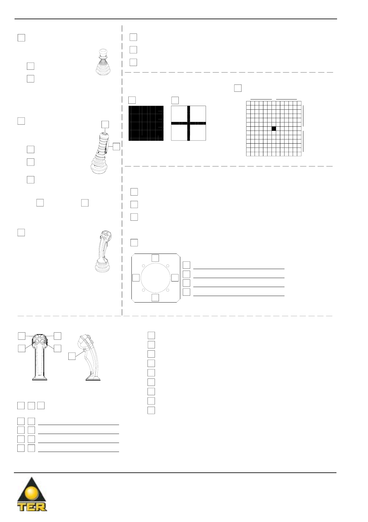
Request form for Romeo non standard joysticks
Request form for Romeo non standard joysticks
Actuators for ergonomic handle
23
45
1
Actuator type* and label letterings
Movement
Stepped - spring return
Stepped - maintained positions
Linear - spring return
Lever guide
Customized lever guide
(not available for proportional Romeo)
6 steps directions A-B
6 steps directions C-D
360° movement
6 steps directions A-B
6 steps directions C-D
Cross movement
Standard lever guide
B
A
0
CD0
*Maximum 5 contacts + 1 common available
Ex.: NO contact in position 1 + 4 buttons A type
NO contact in position 1 + 4 selectors C type
NO contact in position 1 + 2 selectors G type
** In case of use of the electrical interlock function,
connect it to actuator 1
2
3
4
5
Type Lettering
Pos.
Y N Green button NO 1 cont.+1 comm.**
1
P1
P2
Grip type
Knob (IP 65 assembled
in specific enclosure)
Ergonomic handle
(IP 43 assembled
in specific enclosure)
Handle (IP 44 assembled
in specific enclosure)
Free movement
Electrical interlock
(P1 button NO)
Electrical interlock (P1 button
NO) + P2 button NO
Colour of P2 button
black green
Function
Free movement
Mechanical interlock
+
NC/NO contact
(not available for proportional
Romeo)
Function
Blank label
Lifting-Traverse symbols
Trolley-Rotation symbols
1
2
34
1
2
3
4
Pos. Letterings
Customized label
Joystick label
Actuators for positions 2-3-4-5
A
Black button NO 1 contact + 1 common
B
Green button NO 1 contact + 1 common
C
2 position selector ON-OFF 1 contact + 1 common
D
2 position selector MOM-OFF 1 contact + 1 common
E
2 maintained position selector ON-ON 2 contacts + 1 common
F
3 maintained position selector ON-OFF-ON 2 contacts + 1 common
G
2 position spring return selector ON-MOM 2 contacts + 1 common
H
3 position selector MOM-OFF-MOM 2 contacts + 1 common
I
3 position selector ON-OFF-MOM 2 contacts + 1 common

R o m e o -
Romeo -
J o y s t i c k
Joystick
28032014-11
Instructions
When necessary, write the number corresponding to the potentiometer or
to the preset required. Fill in the contact scheme blackening the boxes
corresponding to the positions where the cams close the contacts (each bar
of 13 boxes correspond to a switch; the central box corresponds to the zero
position of the joystick). In the example, the contact is closed in positions 1-2-3
to the left and 3-4 to the right.
6 5 4 3 2 1 0 1 2 3 4 5 6
Potentiometer
1
2.2 kΩ
2
4.7 kΩ
3
10 kΩ
4
Preset only
Potentiometer
Potentiometer
A
B
0
C0D C0D
C0D C0D
A
B
0
A
B
0
A
B
0
CD
A
B
Potentiometer
Potentiometer
A-B LEVER DIRECTION
Stepless proportional joystick
Joystick with switches
Standard outputs (A-B direction) Select a version
Voltage Current PWM
0-10V 4-20mA 0-100%
0-5V 4-12mA 0-50%
0,5-9,5V 4,5-19,5mA 5-95%
0,5-4,5V 4,5-11,5mA 5-45%
LEVER DIRECTION C-D
Customized outputs (A-B direction)
Voltage
(from 0 to 10 V)
Current
(from 4 to 20 mA)
PWM
(from 0 to 100%)
min Lever in central
position max min Lever in central
position max min Lever in central
position max
______V ______V ______V _____mA _____mA _____mA ______% ______% ______%
Select the increase / decrease direction
of the signal
A
B
max
min
A
B
min
max
CD
max min
CD
min max
Select the increase / decrease direction
of the signal
Standard outputs*
Customized outputs
Standard outputs (C-D direction) Select a version
Voltage Current PWM
0-10V 4-20mA 0-100%
0-5V 4-12mA 0-50%
0,5-9,5V 4,5-19,5mA 5-95%
0,5-4,5V 4,5-11,5mA 5-45%
Customized outputs (C-D direction)
Voltage
(from 0 to 10 V)
Current
(from 4 to 20 mA)
PWM
(from 0 to 100%)
min Lever in central
position max min Lever in central
position max min Lever in central
position max
______V ______V ______V _____mA _____mA _____mA ______% ______% ______%
Standard outputs*
Customized outputs
*Select the standard output required. In case of customized outputs, fill in the ‘customized outputs’ table paying attention at the value ranges.
The value of ‘Lever in central position’ must be in between the minimum and maximum values chosen.

TER Tecno Elettrica Ravasi srl
Via Garibaldi 29/31 - 23885 Calco (LC) - Italy
Registered Office - via San Vigilio 2 - 23887 Olgiate Molgora (LC) - Italy
www.terworld.com
The data and the products illustrated in this brochure may be modified without notice. Under no circumstances can their description have a contractual value.
02042013-12
Use and maintenance instructions
Use and maintenance instructions
The Romeo joystick is an electromechanical device for low voltage control circuits (EN 60947-1, EN 60947-5-1) to be used as electric equipment
on machines (EN 60204-1) in compliance with the essential requisites of the Low Voltage Directive 2006/95/CE and the Machine Directive
2006/42/CE.
The Romeo joystick is designed for use in industrialal environments even under severe climatic conditions (working temperatures from -25°C to
+70°C and suitable for use in tropical environments). The equipment is not suitable for use in environments with potentially explosive atmosphere,
corrosive agents or a high percentage of sodium chloride (saline fog). Oils, acids or solvents may damage the equipment. Do not connect more
than one phase to each switch. Do not oil or grease the switches and the control elements.
If the joysticks are equipped with mechanical interlock, do not move the control lever before removing this block by lifting the lower part of the knob
(01), this operations also activates the dedicated central switch.
If the joysticks are equipped with the “Dead Man” button, push the button (P1) to enable movement and while operating eventual push buttons /
selectors (P2, P3, P4, P5) the foreseen functions are activated.
With regard to the conditions for installation, use and evaluation of the essential requisite for safety and the protection of health, the joystick must
be installed so as to ensure adequate protection of the equipment in general and of the active parts in particular (protection against electric shock
and against the penetration of solid bodies and liquids).
The installation of the Romeo joystick shall be carried out by expert and trained personnel. Wiring shall be properly done according to the current
instructions.
Prior to the installation and the maintenance of the joystick, the main power of the machinery shall be turned off.
The joystick is supplied with a bag of accessories including: 4 metric screws (04).
Steps for the proper installation of the joystick
- Drill holes Ø 60 on the chosen support (support with a thickness of 4 mm) (for correct drilling use the special template supplied on request)
-Place the joystick in the hole on the support (press the bellows on the joystick (3) slightly for correct insertion)
- Position the plate (05) with its gasket on the joystick
- Fasten the screws (04) matching the holes on the plate (05) with those on the support and the threaded holes on the joystick (take care to position
the gasket correctly between the joystick and the support)
- Strip the multi-pole cable for a length sufficient for electrical connection with the terminals
- Fasten the multi-pole cable so as to prevent the possibility of external traction on the connections
- Connect the wires to the terminals in accordance with the wiring diagram shown on the instructions; we suggest the use of pin terminals
Steps for routine maintenance
- Check the correct tightening of the screws (04) fastening the joystick to the support
- If there is a mechanical interlock (01), make sure it functions correctly
- If there is a “Dead Man” button (P1), make sure it mechanically functions correctly
- If there are a push buttons / selectors (P2, P3, P4, P5), make sure they mechanically functions correctly
- Check the conditions of the wiring (in particular where wires clamp into the terminals)
- Check the conditions of the bellows (03) on the joystick
Any change to parts of the joystick will invalidate the rating plate and identification data of the device, and render the warranty null and void. In
case of replacement of any part, use original spare parts only.
TER declines all responsibility for damages caused by the improper use or installation of the equipment.
R o m e o -
Romeo -
J o y s t i c k
Joystick
Schema di cablaggio A
Wiring Layout A
3
1
4
5
P1
3
4
5
P2
3
5
P1
P3
P5
P4
4
P2
Schema Cablaggio A
Wiring Layout A
Schema Cablaggio B
Wiring Layout B
Schema Cablaggio B
Wiring Layout B
Disponibile per tutti i modelli
Avaiable for all models
Schema di cablaggio B
Wiring Layout B
1
C
NC
CNC
NC
C
NC
C
NC
NC NC
C
CNC
CNC
NC C
NC C
NC C
1V 3V 4V 6V
1V 2V 5V
A
1V 1V
3V2V
5V 4V
6V
D
10
11
12
13
14
15
16
17
18
9
8
7
6
5
4
3
2
16 16
16 16
16
16
16
17
17
17
17
17
C
NC
C
NC
17
17
B
C
1
23
41012
11
6
9
13
15
7
8
14
CC 26
25
24
23
27
22
1
C
NC
CNC
NC
C
NC
C
NC
NC NC
C
CNC
CNC
NC C
NC C
NC C
1V 3V 4V 6V
1V 2V 5V
A
1V 1V
3V2V
5V 4V
6V
D
10
11
12
13
14
15
16
17
18
19
20
21
9
8
7
6
5
4
3
2
16 16
16 16
16
16
16
17
17
17
17
17
C
NC
C
NC
17
17
B
C
1
23
41012
11
6
9
13
15
7
8
14
C
NC
NO
19
20
21
CC
Rosso
Verde
Bianco 50%
Blu
Dispositivo 1
Device 1
1 2 3
Dispositivo
Device
Posizione
Position
Funzione
Function
Numero Pin
Pin number
23
27
26
25
24
22
Dispositivo 2
Device 2
Dispositivo 3
Device 3
28032014-13
JOYSTICK WITH SWITCHES
TER Tecno Elettrica Ravasi srl
Via Garibaldi 29/31 - 23885 Calco (LC) - Italy
Registered Office - via San Vigilio 2 - 23887 Olgiate Molgora (LC) - Italy
www.terworld.com
The data and the products illustrated in this brochure may be modified without notice. Under no circumstances can their description have a contractual value.
28032014-14
STEPLESS PROPORTIONAL JOYSTICK
3
1
4
5
P1
3
4
5
P2
3
5
P1
P3
P5
P4
4
P2
Dispositivo 1
Device 1
Dispositivo 2
Device 2
Dispositivo 3
Device 3
N. PIN Funzione / Function
1 Uscita interruttore direzione A / Switch output direction A A
2 Uscita interruttore direzione B / Switch output direction B B
3 Uscita interruttore direzione C / Switch output direction C C
4 Uscita interruttore direzione D / Switch output direction D D
5 Comune direzione A/B / Common direction A/B COM_AB
6 Comune direzione C/D / Common direction C/D COM_CD
7Riferimento di massa per le uscite analogiche
Ground reference for analog outputs GND
8 Alimentazione Vac/VDC- / Supply voltage Vac/VDC- VAC/VDC-
9 Alimentazione Vac/VDC+ / Supply voltage Vac/VDC- VAC/VDC+
10
11
12
13
14
15
16 Non connesso / Not connected
17 Non connesso / Not connected
18 Uscita PWM direzione A/B / PWM output direction A/B PWM_AB
19 Uscita PWM direzione C/D / PWM output direction C/D PWM_CD
20 Non connesso / Not connected
21 Non connesso / Not connected
22 Non connesso / Not connected
23 Non connesso / Not connected
24 Uscita analogica in tensione direzione C/D
Voltage analog output direction C/D V_CD
25 Uscita analogica in tensione direzione A/B
Voltage analog output direction A/B V_AB
26 Uscita analogica in corrente direzione C/D
Current analog output direction C/D I_CD
27 Uscita analogica in corrente direzione A/B
Current analog output direction A/B I_AB
1
NC
C
NC
CNC NC C
1V
1V
A
1V1V
D
10
11
12
13
14
15
9
8
7
6
5
4
3
2
5
5
66
B
C
2
1
3
4
C26
25
24
23
27
22
16
17
18
19
20
21
Table of contents


