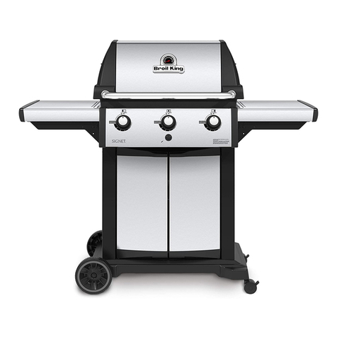
Tera Gear 13 01 3008TG Quick start guide

1
Loblaws Inc.,
1 President’s Choice Circle,
Brampton, Ontario
L6Y 5S5
WARNING
You must read this owner’s guide before operating
your gas grill. Failure to follow these instructions
could result in re or explosion that could cause
property damage, personal injury or death.
For your safety: This gas appliance is designed
for outdoor use only and shall not be used in a
building, garage or any other enclosed area.
Do not use in or on boats or recreational vehicles.
WARNING
1. Improper installation, adjustment, alteration,
service or maintenance can cause injury or
damage to property.
2. Read the assembly, installation, operation and
maintenance thoroughly before assembling,
installing, or servicing the equipment.
3. Failure to follow these instructions could result
in re or explosion which could cause property
damage, personal injury or death.
Stainless Steel 60,000BTU BBQ
natural gas
assembly instructions and
owner’s guide
MODEL NUMBER:
13 01 3008TG
SERIAL NUMBER:
natural gas
TG3008 NG U&C-2012 FA.indd 1 12-09-26 4:36 PM

2
THIS GAS APPLIANCE IS DESIGNED FOR OUTDOOR USE ONLY.
DANGER
If you smell gas:
1. Shut off gas to the appliance.
2. Extinguish any open flames.
3. Open the lid.
4. If odor persists, keep away from the appliance and
immediately call your gas supplier or the fire department.
DO NOT RETURN THE BARBECUE TO STORE.
For assistance, call Customer Service at 1-800-737-8815
Monday to Friday from 9 a.m. to 5 p.m. Eastern Standard Time.
WARNING:
Do not ignite this gas appliance without rst reading the operating instructions in this manual.
Save these instructions for future reference.
NOTICE TO INSTALLER:
These instructions must be left with the owner and the owner should keep them for future reference.
NOTICE TO CONSUMER:
Retain this manual for future reference.
WARNING:
Follow all leak check procedures carefully in this manual prior to barbecue operation.
Do this even if the barbecue was dealer-assembled.
Do not repair or replace any parts of the grill unless specically recommended in this manual or by
customer service. All other service and maintenance should be performed by a qualied technician.
WARNING:
Do not store or use gasoline or other ammable liquids, vapours or materials in the vicinity of this or
any other appliance.
Safety Instructions
TG3008 NG U&C-2012 FA.indd 2 12-09-26 4:36 PM

3
BEFORE USING THIS GRILL PERFORM THE SAFETY CHECK.
1. Read and understand the manual.
2. Perform the leak test as found on page 30.
3. Ensure that the barbecue is not positioned under unprotected construction, against a wall, near
aluminum or vinyl siding, windows, fencing or anything else that may be ammable.
4. Inspect and clean burner tubes to avoid ash res caused by spider webs and other blockages.
See page 33 for cleaning instructions.
5. Avoid dangerous grease res by cleaning out the grease cup and grease tray. See instructions
on page 33.
6. Before opening the gas supply, ensure that the lid is open, burner knobs are in the o position,
gas is turned o and the regulator is properly attached to the tank.
7. Follow the proper lighting procedure on page 31.
Table of Contents
General Warnings 4
Assembly Instructions 6
Connecting to Natural Gas Supply 29
Leak Testing 30
Operating Main Burners 31
Operating the Side Burner 32
Cleaning 32
Seasonal Cleaning 34
Tips for Cooking 35
Trouble Shooting 36
TG3008 NG U&C-2012 FA.indd 3 12-09-26 4:36 PM

4
General Warnings
This barbecue is not convertible to propane. Any
attempt to do so could result in injury or damage to
property and will void the warranty.
WARNINGS
Failure to follow the dangers, warnings and cautions
contained in this Owner’s Manual may result in re or
explosion causing property damage, personal injury or
death.
Incorrect assembly may be dangerous. Please carefully
follow the assembly instructions. Do not assemble with
missing or damaged parts. If you do not understand
the instructions or need replacement parts, contact
Customer Service at 1-800-737-8815.
Check your local building codes for the proper method of
installation or in the absence of local codes, with either
the National Fuel Gas Code, ANSI Z223.1/NFPA 54,
Natural Gas and Propane Installation Code, CSA B149.1,
or Propane Storage and Handling Code, B149.2
The use of alcohol, prescription or non-prescription drugs
may impair an individual’s ability to properly assemble or
safely operate this barbecue.
Always place your barbecue on a hard and level surface. An
asphalt surface or wooden deck may not be acceptable.
The gas barbecue should be thoroughly cleaned on a
regular basis.
If the barbecue has been stored or left unused for a
period of time, it should be checked for gas leaks and
burner obstructions before use. See instructions in this
manual for correct cleaning and leak testing procedures.
Do not enlarge valve orices or burner ports when cleaning
the valves or burners. Follow the proper procedures as
outlined in the burner cleaning section of this manual.
Keep ventilation openings clear of debris.
Do not operate the gas barbecue if there is an odor of
gas present or a gas leak.
Do not use a ame to check for gas leaks.
Combustible materials should never be within 24 inches
(61 cm) of the back or sides of your gas barbecue.
Always position the barbecue where there is ample air
ow for combustion and ventilation, but never in the path
of a strong wind.
Do not use this barbecue under an overhead combustible
surface or covered area such as a gazebo, umbrella
porch or awning.
Do not put a barbecue cover or anything ammable on
or in the storage area under the barbecue or on the side
shelves. Keeping outdoor cooking gas appliance area
clear and free from combustible materials, gasoline and
other ammable vapors and liquids.
Your gas barbecue should never be used by children. Do
not let children or pets play around or below the grill or in
the cart. Never allow children or pets to crawl inside the
cart. Accessible parts of the barbecue may be very hot.
You should exercise care when operating your gas
barbecue. It will be hot during cooking or cleaning and
should never be left unattended or moved while in
operation.
When using the barbecue do not touch the grill rack, lid,
re box or anything in the immediate vicinity of these
parts, as they can become extremely hot and may cause
serious burns.
Never lean over an open grill.
Use only dry pot holders and oven mitts. Moist or damp
pot holders or oven mitts on hot surfaces may cause
burns from steam. Do not use a towel or a bulky cloth in
place of pot holders or oven mitts, as they may touch hot
portions of the grill rack.
For personal safety, wear appropriate clothing. Loose-
tting clothing should never be worn while using this
appliance. Some synthetic bers are highly ammable
and should not be worn while cooking.
Should the burners go out while in operation, turn all
gas valves o. Open the lid and wait ve minutes before
attempting to relight, using the igniting instructions.
Do not use charcoal, lighter uid or lava rock in your gas
barbecue.
Do not use aluminum foil to line the grill racks or the re
box. This can interfere with air ow or trap excessive heat
in the re box or control area.
Should a grease re occur, turn o all burners and leave
lid closed until re is out.
Only the hose assembly supplied with the unit should
be used. Never substitute hoses for those supplied with
the grill. If a replacement is necessary contact Customer
Service for a replacement.
Do not attempt to disconnect any gas tting while your
barbecue is in operation.
Do not repair or replace any part of the grill unless
specically recommended by the manual or Customer
Service. All other service should be referred to a qualied
technician.
TG3008 NG U&C-2012 FA.indd 4 12-09-26 4:36 PM

5
Keep any electrical supply cord and the fuel supply hose
away from any heated surfaces and the grease cup and
tray where hot grease could drip down.
Combustion by-products produced when using
this product contain chemicals known to the state
of California to cause cancer, birth defects or other
reproductive harm.
Do not build this model of grill in any built-in or slide-in
construction. Ignoring this warning could cause re or
explosion that can cause property damage, personal
injury or death.
Do not heat unopened food containers as a build-up of
pressure may cause the container to burst causing injury
or damage to property.
This barbecue is not intended for commercial use.
Natural Gas Units Only:
Use the hose assembly that is supplied with your gas
barbecue.
Do not attempt to disconnect the gas regulator and hose
assembly or any gas tting while your barbecue is in
operation.
Your natural gas grill has been designed to operate on
natural gas only, at a pressure of seven inches water
column (7” W.C.).
Check with your gas utility for local gas pressure,
because in some areas natural gas pressure varies. Also,
check with your gas company or with local building
codes for instructions to install gas supply line or call a
licensed and qualied installer.
It is recommended that an ON/OFF manual shut–o valve
be installed at the gas supply source:
Outdoors after the gas line exits outside wall and before
quick disconnect or before gas supply line enters ground.
Pipe sealing compound or pipe thread tape of the type
resistant to the action of natural gas must be used on all
male pipe threads. Apply compound or tape to at least
the rst three to four threads when making connections.
Never store or use gasoline or other volatile substance in
the vicinity of this grill.
During high pressure testing, in excess of 1/2 psi (3.5kPa)
your gas grill and its individual shuto valve must be
disconnected from the gas supply piping system.
During low pressure testing, equal to or less than 1/2
psi (3.5kPa), your gas grill must be isolated from the gas
supply piping system by closing its individual manual
shuto.
Natural Gas Characteristics: Natural Gas is ammable,
explosive under pressure and heavier than air so it will
settle and pool in low areas and prevent dispersion.
Natural Gas has a distinct smell. You should be aware of
this smell.
If you see, smell or hear the hiss of escaping gas from the
fuel line:
1. Move away from fuel line.
2. Do not attempt to correct the problem yourself.
3. Call your re department.
The total consumption (per hour) of this grill with all
burners set to “MAX” is 60,000 BTU/hr.
Four main burners: 48,000 BTU/hr
Side burner: 12,000 BTU/hr
TG3008 NG U&C-2012 FA.indd 5 12-09-26 4:36 PM

6
Assembly Instructions
INTRODUCTION
Do not return this product to store.
For assistance call Customer Service at 1-800-737-8815.
Please have the following information available.
Serial Number
The serial number can be found inside the front left door
of the barbecue on the top left hand corner of the rating
label. It can also be found on the cover of this manual.
Model Number
The model number is located on the front of this manual
and in the top left-hand corner of the rating label.
For easiest assembly:
1. Make sure all the parts are present. If parts are
missing or damaged, contact Customer Service.
2. To avoid losing small components, assemble the
barbecue on a smooth, level surface.
3. Clear an area large enough to lay out all the
components and hardware.
4. You must follow all steps in order to properly
assemble your barbecue.
5. To properly align the frame and doors, assemble
grill on a at and level surface.
To complete your assembly you will need:
1. A #2 Phillips head screw driver
2. Leak detection solution see
(Leak Detection section on page 30)
Parts List
CODE PART QTY
1 Fire Box Assembly 1
2 Warming Rack 1
3 Cooking Grill 2
4 Heat Tent 4
5 Grease Tray Assembly 1
6 Grease Cup 1
7 Side Burner Grate 1
8 Side Burner Electrode 1
9 Side Burner Assembly 1
10 Side Burner 1
11 Side Burner Control Panel 1
12 Side Burner Knob 1
13 Side Table Assembly 1
14 Side Table Control Panel 1
15 Side Table Handle 1
16 Left Front Leg 1
17 Left Rear Leg 1
18 Right Front Leg 1
19 Right Rear Leg 1
20 Door Transom 1
21 Left Cart Side Panel 1
22 Right Cart Side Panel 1
23 Left Front Door 1
24 Right Front Door 1
25 Door Handle 2
26 Bottom Shelf Assembly 1
27 Hose Restraint Clip 1
28 Cart Support Bracket 2
29 Bottom Skirt - Front 1
30 Bottom Skirt - Left 1
31 Bottom Skirt - Right 1
32 Caster 2
33 Locking Caster 2
34 Lighting Rod 1
TG3008 NG U&C-2012 FA.indd 6 12-09-26 4:36 PM

7
Parts Diagram
TG3008 NG U&C-2012 FA.indd 7 12-09-26 4:36 PM

8
Hardware Reference Diagram
CODE PART QTY
A M6x12mm Bolt 38
B M6x8mm Bolt 4
C M5x8mm Bolt 4
D M6x40mm Bolt 2
E Washer 6
F M4x10mm Bolt 12
1:1 SCALE
TG3008 NG U&C-2012 FA.indd 8 12-09-26 4:36 PM

9
Assembly
STEP 1
Attach the Left Front Leg (16) and Right Front Leg (18)
to the Bottom Shelf Assembly (26) using one
M6x12mm Bolt on each leg (A).
Tighten the bolts with the screwdriver.
STEP 2
Attach the Left Rear Leg (17) and Right Rear Leg (19)
to the Bottom Shelf Assembly (26) using one
M6x12mm Bolt (A) on each leg.
Tighten the bolts with the screwdriver.
16 26
26
18
17
19
Ax2
Ax2
1:1 SCALE
TG3008 NG U&C-2012 FA.indd 9 12-09-26 4:36 PM

10
Assembly
STEP 3
A. Attach the Right Cart Side Panel (22)
to the Right Front Leg (18) and
Right Rear Leg (19) using four
M6x12mm Bolts (A).
Tighten the bolts with the
screwdriver.
B. Attach one of the Cart Support Brackets (28)
to the Right Rear Leg (19) and the
Bottom Shelf Assembly (26) using two
M6x12mm Bolts (A).
Tighten the bolts with the screwdriver.
22
19
19
18
28
Ax4
Ax2
TG3008 NG U&C-2012 FA.indd 10 12-09-26 4:36 PM

11
Assembly
STEP 4
A. Attach the Left Cart Side
Panel (21) to the Left Front Leg (16)
and Left Rear Leg (17) using four
M6x12mm Bolts (A).
Tighten the bolts with the
screwdriver.
B. Attach the Cart Support Bracket (28)
to the Left Rear Leg (17) and the
Bottom Shelf Assembly (26) using two
M6x12mm Bolts (A).
Tighten the bolts with the screwdriver.
21
16 17
17
28
Ax4
Ax2
TG3008 NG U&C-2012 FA.indd 11 12-09-26 4:36 PM

12
Assembly
STEP 5
A. Attach the two Locking
Casters (33) to the Left Rear Leg (17)
and the Right Rear Leg (19).
B. Attach the two Casters (32) to
the Left Front Leg (16) and the
Right Front Leg (18).
STEP 6
Attach the Bottom Skirt Front (29) on the
Bottom Shelf Assembly (26) using four M4x10mm Bolts (F).
Align the edges of the Bottom Skirt Front with the
edges of the Bottom Shelf Assembly.
Tighten the bolts with the screwdriver.
33
33
32
32
17
16
19
18
29
26
Fx4
TG3008 NG U&C-2012 FA.indd 12 12-09-26 4:36 PM

13
Assembly
STEP 7
Attach the Bottom Skirt Right (31) to the
Bottom Shelf Assembly (26) and the
Bottom Skirt Front (29) using four
M4x10mm Bolts (F). Align the edge
of the Bottom Skirt Right with the
front edge of the Bottom Skirt Front.
Tighten the bolts with the screwdriver.
STEP 8
Attach the Bottom Skirt Left (30) to the
Bottom Shelf Assembly (26) and the
Bottom Skirt Front (29) using four
M4x10mm Bolts (F). Align the edge
of the Bottom Skirt Left with the
front edge of the Bottom Skirt Front.
Tighten the bolts with the screwdriver.
29
29
30
31
26
26
Fx4
Fx4
TG3008 NG U&C-2012 FA.indd 13 12-09-26 4:36 PM

14
Assembly
STEP 9
Attach the Door Transom (20) to the Left Front Leg (16)
and Right Front Leg (18) using two
M6x40mm Bolts (D).
Tighten the bolts with the screwdriver.
STEP 10
A. Ensure the brakes on the locking casters are rmly in the locked “on” position before continuing.
B. Use this opportunity to make sure all the screws are tight and the frame is square because some
screws may loosen during assembly.
STEP 11
Attach the two Door Handles (25)
to the Left Front Door (23) and the
Right Front Door (24) using
M5x8mm Bolts (C).
Tighten the bolts with
the screwdriver.
20
16
23
25 25
24
18
Dx2
Cx2
TG3008 NG U&C-2012 FA.indd 14 12-09-26 4:36 PM

15
Assembly
STEP 12
A. Place the Left Front
Door (23) on the left
hand door post of the
Bottom Skirt Front (29).
B. Depress the spring
post on the bottom of the
Door Transom (20), then align
the hole in the top of the
door with the spring post.
You should hear a click
when the door is properly
aligned and the door
should be attached.
C. Place the Right Front
Door (24) on the right
hand door post of the
Bottom Skirt Front (29).
D. Depress the spring
post on the bottom of the
Door Transom (20), then
align the hole in the top of
the door with the spring post.
You should hear a click when
the door is properly aligned
and the door should be
attached.
29
29
29
29
23
24
20
20
23
24
23
24
20
20
ONLINE VIDEO: STEP 12
To view a detailed video presentation for this step
of the assembly visit www.bbqinstructions.com/
2013/step-12
or scan this QR code with a
web-enabled Smart Device.
TG3008 NG U&C-2012 FA.indd 15 12-09-26 4:36 PM

16
Assembly
STEP 13
Attach the Side Table Handle (15)
to the Side Table Assembly (13)
using two M6x12mm Bolts (A)
placing a washer (E) on each end
between the Side Table Assembly (13)
and the M6x12mm Bolts (A).
Tighten the bolts with the screwdriver.
STEP 14
Place the Side Table Assembly (13)
on the Left Rear Leg (17) and
Left Front Leg (16) and attach
using three M6x12mm Bolts (A).
Tighten the bolts with
the screwdriver.
15
13
13
13
13
13
17
17
16
16
Ax2
Ax3
Ex2
TG3008 NG U&C-2012 FA.indd 16 12-09-26 4:36 PM

17
34
Assembly
STEP 15
A. Place the Side Burner
Assembly (9) on the
Right Front Leg (18) and
Right Rear Leg (19).
B. Attach the Lighting Rod (34)
to the Right Rear Leg (19) and
Side Burner Assembly (9)
using two M6x12mm Bolt (A).
C. Attach the Side Burner
Assembly (9) to the Front Leg
using one M6x12mm Bolt (A).
Tighten the bolts with the
screwdriver.
9
9
9
18
18
19
19
Ax2
Ax1
34
TG3008 NG U&C-2012 FA.indd 17 12-09-26 4:36 PM

18
Assembly
STEP 16
WARNING:
This step requires two people
to lift the Fire Box Assembly.
Failure to do so may result
in personal injury or damage
to the BBQ.
Place the Fire Box Assembly (1) on
top of the trolley attaching the
Fire Box Assembly to the Left
Front Leg (16), Left Rear Leg (17),
the Right Front Leg (18) and
Right Rear Leg (19) using a
total of four M6x12mm Bolts (A).
Tighten the bolts with
the screwdriver.
ONLINE VIDEO: STEP 16-17
To view a detailed video presentation for this step
of the assembly visit www.bbqinstructions.com/
2013/step-16-17
or scan this QR code with a
web-enabled Smart Device.
Ax4
1
1617
16
17
19
19
18
18
TG3008 NG U&C-2012 FA.indd 18 12-09-26 4:36 PM

19
Assembly
STEP 17
A. From the inside of the re box attach the Fire Box Assembly (1) to the Side Table Assembly (13)
two M6x12mm Bolts (A) placing a Washer (E) between the M6x12mm Bolts (A) and the
Fire Box Assembly (1). Tighten the bolts with the screwdriver.
113
Ax2
Ex2
TG3008 NG U&C-2012 FA.indd 19 12-09-26 4:36 PM

20
Assembly
STEP 17
B. Attach the Fire Box Assembly (1) to the Side Burner Assembly (9) two M6x12mm Bolts (A) placing a
Washer (E) between the M6x12mm Bolts (A) and the Fire Box Assembly (1). Tighten the bolts with the
screwdriver.
ONLINE VIDEO: STEP 16-17
To view a detailed video presentation for this step
of the assembly visit www.bbqinstructions.com/
2013/step-16-17
or scan this QR code with a
web-enabled Smart Device.
Ax2
Ex2
91
TG3008 NG U&C-2012 FA.indd 20 12-09-26 4:36 PM
Table of contents
Other Tera Gear Grill manuals

Tera Gear
Tera Gear GSF2616AC Operation and maintenance manual
Tera Gear
Tera Gear GSS2020 User manual
Tera Gear
Tera Gear GSF2818A User manual

Tera Gear
Tera Gear Weekend Warrior GSF3916 User manual

Tera Gear
Tera Gear PC14 User manual

Tera Gear
Tera Gear TER 25K BTU PRO User manual

Tera Gear
Tera Gear 13 01 3007TG Quick start guide

Tera Gear
Tera Gear GSS2520JA User manual

Tera Gear
Tera Gear GSF2520KL User manual

Tera Gear
Tera Gear TG 1201 2561 User manual


