TERMA MAX K160S User manual

MAXImpact Power
Operators Instruction
& Parts Manual
MAX K160S
Version 2023
Model: MAX K160S
Registration number:.........................
Purchase date:........................

2

3
Table of contents: Page
1TECHNICAL INFORMATION ....................................................................................................................... 4
1.1 MAX K160S .............................................................................................................................................. 4
1.2 AIR HOSE.................................................................................................................................................... 4
1.3 MAX-LUBRICATOR....................................................................................................................................... 4
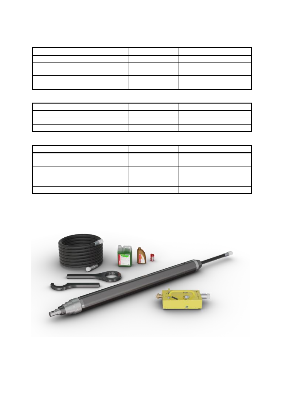
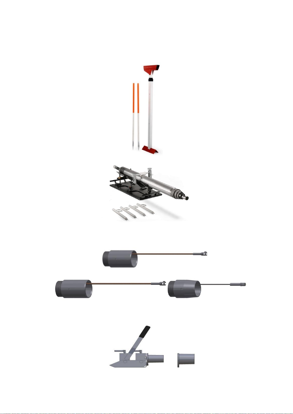
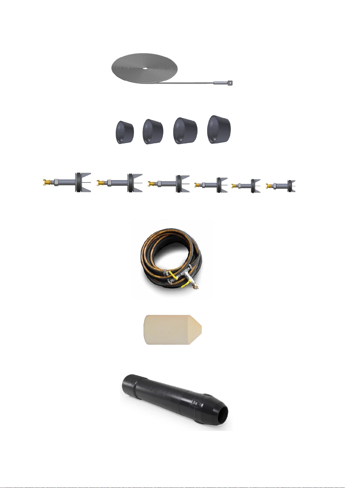
2ACCESSORIES ............................................................................................................................................ 5
3SAFETY INSTRUCTIONS ............................................................................................................................. 7
3.1 WARNING SIGNS:......................................................................................................................................... 7
3.2 PROHIBITORY SIGNS:..................................................................................................................................... 8
3.3 MANDATORY SIGNS:..................................................................................................................................... 8
4USE OF MAX K160S................................................................................................................................... 9
5OPERATION PRINCIPLE ............................................................................................................................. 9
6CONSTRUCTION...................................................................................................................................... 10
6.1 MAX K160S ............................................................................................................................................ 10
6.2 AIR PRESSURE HOSE .................................................................................................................................... 11
6.3 MAX-LUBRICATOR WITH REVERSING MECHANISM........................................................................................... 12
7TRANSPORTATION.................................................................................................................................. 13
8PREPARATIONS BEFORE USE................................................................................................................... 14
8.1 GENERAL INSTRUCTIONS.............................................................................................................................. 14
8.2 STARTING PIT............................................................................................................................................. 14
8.3 TARGET PIT ............................................................................................................................................... 15
9INSTRUCTIONS........................................................................................................................................ 15
9.1 SAFETY INFORMATION................................................................................................................................. 15
9.2 CONVERT THE MAX K160S......................................................................................................................... 15
9.3 CONNECTING THE AIR HOSE......................................................................................................................... 17
9.4 FUNCTIONS OF THE LUBRICATOR ................................................................................................................... 18
9.5 ALIGNMENT OF THE MAX K160S ................................................................................................................. 18
9.6 SOLO-BORING ........................................................................................................................................... 19
9.7 REVERSING MAX K160S ............................................................................................................................ 20
9.8 MANUAL PULLING OF PLASTIC PIPES ............................................................................................................... 21
9.9 DIRECT INSTALLING PE/PVC PIPES................................................................................................................ 21
9.10 INSTALLING STEEL PIPES (RAMMING-JACKING).................................................................................................. 22
9.11 CLEANING OF STEEL PIPES AFTER RAMMING ..................................................................................................... 23
9.12 EXPANDING DRILL HOLE WITH WIDENING ACCESSORIES. ..................................................................................... 25
9.13 INSTALLING OF PIPES MM WITH EXPANDERS..................................................................................................... 26
9.14 AFTER CARE .............................................................................................................................................. 27
10 MAINTENANCE ................................................................................................................................... 27
10.1 DAILY INSPECTION ...................................................................................................................................... 27
10.2 WHEN MAX HAS NOT BEEN IN USE FOR A WHILE.............................................................................................. 28
10.3 TECHNICAL INSPECTIONS.............................................................................................................................. 29
11 TROUBLESHOOTING............................................................................................................................ 30
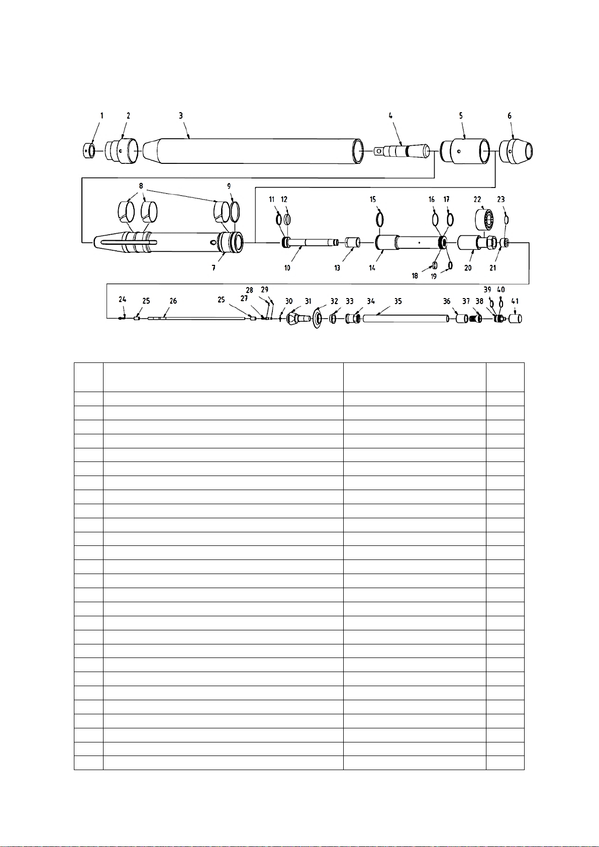
12 SPARE PARTS ...................................................................................................................................... 32
12.1 MAX K130S –MOLE SPARE PARTS LIST ......................................................................................................... 32
12.2 PNEUMATIC AIR HOSE 20 M SPARE PARTS LIST ................................................................................................. 34
12.3 LUBRICATOR WITH REVERSING MECHANISM..................................................................................................... 36

4
1Technical information
1.1 MAX K160S
Parameter
Unit
Value
Diameter
[mm]
160
Lenght
[mm]
2110
Weight
[kg]
203
Air consumption, min (recommended)
[m3/min]
3,5 (4,5)
Air pressure
[atm]
7
1.2 Air hose
Parameter
Unit
Value
Diameter
[mm]
31,5
Lenght
[m]
20
Weight
[kg]
30,5
1.3 MAX-Lubricator
Parameter
Unit
Value
Length (including caps)
[mm]
665
Width
[mm]
232
Height
[mm]
180
Weight (without oil)
[kg]
15,8
Tank capacity
[L]
3,1
Air pressure
[atm]
7

5
2Accessories
With MAX K160S the following accessories can be used:
a) For the alignment of MAX:
-Optical level set
-Starting platform
b) For installing plastic tubes, directly behind the machine:
−Tools for pulling PE/PVC pipes diameter 125, 140 and 160 (with rope)
−Tensioner with replaceable sleeves

6
-Steel pulling rope Ø8 mm with interconnector
c) for ramming steel pipes:
-Cones: S356406, S280340, S 230290, S159245,
d) To clean the pipes from debris after ramming the pipes:
−Pipe plugs: PW406, PW355, PW 323, PW 273, PW 219, PW 159,
-Air pressure hose with valve (for the pipe plugs)
-Foam pipeline pig
e) for making drilling holes up to Ø219 and for installing pipes Ø180, Ø200 :
- Expanders / Calibrators: PO 200, PO219

7
- Tip towing for working with calibrators
- Extending rope for towing tool
f) for lubrication we recommend to use EkoMAX Oil. An environmental friendly product that consists
of bio-degradable components. The EkoMAX oil lubricant is available in 5 and 20 liter canisters.
3Safety Instructions
Please note specific safety requirements as explained by procedures called out in this manual. Failure
to follow these instructions could result in serious personal injury or death. All tools, materials and
equipment manufactured and supplied by TERMA, are designed to be used by qualified and trained
personnel only. TERMA will not be held liable for any injury or damage to either people or property
resulting from the misuse of TERMA equipment.
3.1 Warning signs:
Danger to people, this symbol is used in conjunction with an inscription that
says danger!
Danger of heavy swinging loads!

8
Danger of underground utilities!
Danger of explosion!
Entrapment hazard!
High Air pressure!
Danger of burning!
3.2 Prohibitory Signs:
General prohibition signs; this symbol is used in conjunction with a suffix that
makes statements about the ban.
No unauthorized persons allowed!
3.3 Mandatory Signs:
Wear ear protection!
Wear safety glasses!

9
Wear hands protection!
Do not start, operate or service MAX until you have read and understood the
operator’s manual.
Failure to do so may result in serious injury!
4Use of MAX K160S
The MAX K160S is to be used to execute tunneling and for the use of appropriate accessories for
drawing PE, PVC pipes and Steel pipes. Using the MAX K160S for other purposes is not permitted. The
manufacturer will not be held responsible for any damage sustained through improper use of the
MAX K160S.
5Operation principle
The MAX K160S is a pneumatic earth piercing tool, which is driven through the ground by
compressed air. Like any pneumatic tool, MAX requires a compressor with adequate capacity for
optimal operation. To ensure the longevity of the MAX, over pressure (max 7 atm) should be avoided
at all times.
The compressed air is passed through the MAX-oiler with the compressed air hose attached to the
MAX –it is this mechanism that moves the MAX. The exhausted air leaves the MAX via its backside.
The MAX lubricator device is equipped with a pneumatic valve to enable a change of direction by
simply moving the handle from position F to position R

10
6Construction
6.1 MAX K160S
Drawing 6.1.1
No.
Name
Item number
QTY
1.
Stepped head nut
PMNAK-M160-00.09
1
2.
Stepped head
PMNAS-M160-00.01
1
3.
Cylinder
PMCYL-M160-00.02
1
4.
Chisel
PMPRZ-M160-00.08
1
5.
Control stud housing
PMTSR-M160-00.03
1
6.
Reverse cone with pulling eyes
WAHW160
1
7.
Impact piston
PMBIJ-M160-00.05
1
8.
Piston teflon sliding tapes
PMPRB-M160-00.06
3
9.1.
Piston seal (Teflon)
PMUSB-M160-00.07
1
9.2.
Piston seal (O-ring 121x3,5 SI)
MTSORSI0029
2
10.
Control rod
PMRUS-S160-00.06
1
11.1.
Control rod teflon seal
PMUS1-S160-00.04
1
11.2.
Control rod seal (O-ring 58x5 70NBR)
MTSORNB0083
1
12.
Control rod sliding tape I
PMPT1-S160-00.13
1
13.
Elastic damper
PMAMOR-S160-00.14
1
14.
Control piston
PMTLS-S160-00.01
1
15.
Control piston teflon seal
PMUTS-S160-00.02
1
16.
Seal (O-ring 77x3,5 SI)
MTSORSI0032
1
17.1.
Control piston teflon seal II
PMUS2-S160-00.03
1
17.2.
Control piston seal II (O-ring 74x3,5 SI)
MTSORSI0031
1
18.
Control rod sliding tape II
PMPT2-S160-00.05
1
19.1.
Control piston teflon seal III
PMUS3-S160-00.15
1
19.2.
Control piston seal III (O-ring 44,7x3 SI)
MTSORSI0034
1
20.
Control cylinder
PMCYLSTR-S160-00.07
1
21.
Splitter
PMROS-S160-00.09
1
22.
Elastic block
PMLSR-S160-00.08
1
23.
Splitter seal (O-ring 52x3 SI)
MTSORSI0030
1

11
24.
Control hose connector
PMKWC-S130-00.09
1
25.
Control hose crimping ferrule M130, M160, M180
PMTULZW-W130-00.11-M1
2
26.
Control hose 0,7 m
MTSWG0006
m
27.
Control hose barbed coupling (male)
PMLWCM-W130-00.07
1
28.
Retaining ring (E-clip) M130, M160, M180
MMEMNPZ0002
1
29.
Control hose seal (O-ring 6x2)
MTSORNB0054
1
30.
Control hose cross spacer M130
PMWWC-W130-00.08
1
31.
Outer hose barbed connector
PMKWG-S160-00.10
1
32.
Exhaust flap M160
MTSORIU0021
1
33.
Control stud supporting washer M160
PMPDKS-S160-00.12-P1
1
34.
Outer hose nut connector M180S
PMNKKWG-S180-00.16
1
35.
Outer hose 0,6 m
MTSWG0013
m
36.
Outer hose crimping ferrule M130, M160, M180
PMTULZW-W130-00.10-M1
1
37.
Outer hose barbed coupling female M130
PMLWG-W130-00.04
1
38.
Outer hose quick coupler (male) M130, M160,
M180
PMSRB-W130-00.05-M1
1
39.
Coupler seal/Dirt plug seal (O-Ring 36x5)
MTSORNB0036
1
40.
Coupler seal (O-ring 40,2x3)
MTSORNB0039
1
41.
Dirt cap (female)
PMZAZ-W130-00.06-M1
1
…
Control whip hose, complete (Pos. 24, 25 x 2, 26 x
0.7, 27, 28, 29, work)
WAWKC160K
1
…
Outer whip hose, complete (Pos. 35 x 0.8, 36, 37,
work)
WAWZ160
1
...
Seal kit M160 basic (Pos. 8 x 3, 9.1., 9.2. x 2, 15, 29)
WAUM160M
1
...
Seal kit M160 complete (Pos. 8 x 3, 9.1., 9.2. x 2,
11.1., 11.2., 12, 15, 16, 17.1., 17.2., 18, 19.1., 19.2.,
23, 29, 39, 40)
WAUK160
1
6.2 Air pressure hose
Drawing 6.2.1
Nr.
Name
Art.
Q-ty
1.
Dirt plug (male)
PMZAW-W130-00.01-M1
1
2.
Coupler seal/Dirt plug seal (O-Ring 36x5)
MTSORNB0036
2
3.
Outer hose quick coupler (female)
PMLWZ-W130-00.03
1
4.
Coupler seal (O-Ring 36x3)
MTSORNB0035
1
5.
Coupler nut
PMNAW-W130-00.02
1
6.
Control hose cross spacer M130
PMWWC-W130-00.08
2
7.
Control hose barbed coupling (female)
PMLWCZ-W130-00.09
1
8.
Retaining ring (E-clip) M130, M160, M180
MMEMNPZ0002
2
9.
Control hose crimping ferrule M130, M160, M180
PMTULZW-W130-00.11-M1
2
10.
Outer hose barbed coupling female M130
PMLWG-W130-00.04
2
11.
Outer hose crimping ferrule M130, M160, M180
PMTULZW-W130-00.10-M1
2

12
12.
Outer hose 20 m
MTSWG0013
m
13.
Control hose 20 m
MTSWG0006
m
14.
Control hose barbed coupling (male)
PMLWCM-W130-00.07
1
15.
Control hose seal (O-ring 6x2)
MTSORNB0054
1
16.
Coupler seal (O-ring 40,2x3)
MTSORNB0039
1
17.
Outer hose quick coupler (male) M130, M160,
M180
PMSRB-W130-00.05-M1
1
18.
Dirt cap (female)
PMZAZ-W130-00.06-M1
1
…
Control hose 20m, complete M130, M160, M180
(Pos. 7, 9 x 2, 13 x 20, 14, 15, work)
WAWWC130W
1
…
Air supply/control hose 20 m, complete M130,
М160, М180
WAWZ13020
1
6.3 MAX-Lubricator with Reversing Mechanism
Drawing 6.3.1
Nr.
Name
Art.
Q-ty
1
GEKA dust cap with chain 42 mm
MMEHYZS0002
1
2
GEKA GZ-Coupling 42 mm 3/4"
MMEHYZL0002
1

13
3
Splitter II
PMRZG2-OL130-00.01
1
4.1.
XGE 6LR fitting from 1/4" straight connector
MMEHYZL0006
4
4.2.
DPR 6L/S compression ring from 1/4"" straight
connector
MMEMNIN0004
4
4.3.
Nut M12x1.5 M 6L from the straight connector
1/4""
MMEMNNA0006
4
5
Ball valve 3/4"
MMEHYZA0004
1
6
Threaded plug GN 749 1/8"
MMEMNKR0002
1
7
Union fitting 3/4"
MMEHYSR0001
1
8
Oil level sight glass 3/4"
MMEMNIN0008
1
9
Tank container
PMZZM-OL130-01.00-M1
1
10
Splitter I (set)
PMRZG1-OL130-03.00-M1
1
11
Straight standpipe hose tail 130
PMKWO-OL130-00.06
1
12
Outer hose connector (female) M130
PMLWZ-W130-00.03
1
13
Air hose nut M130
PMNAW-W130-00.02
1
14
End cap M130, M160, M180 (male)
PMZAW-W130-00.01-M1
1
15
O-ring 70NBR PN-90/M-73092
MTSORNB0036
1
16
O-ring 36x3 70NBR PN-90/M-73092
MTSORNB0035
1
17
O-ring 30,2x3 of oil cap, 70NBR
MTSORNB0032
1
18
Oil cap
PMKWO-OL130-04.00
1
19
Needle valve
PMIGL-OL130-02.00
1
20
Gland (stuffing box)
PMDŁ-OL130-02.03
1
21
Clamping plate
PMJAR-OL130-00.04-M2
1
22
Flow control knob
PMPOL-OL130-00.05-M2
1
23
Hydraulic pipe fi6x1
MMERUHY0001
0,39 m
24
Hydraulic pipe fi6x1
MMERUHY0001
0,57 m
25
Needle seat
PMGNIG-OL130-02.01
1
26
Needle seal (O-ring 18x2)
MTSORNB0011
2
27
Needle seal (O-ring 8x2)
MTSORNB0056
2
28
Gland seal (O-ring 10x2)
MTSORNB0001
1
29
Clamping plate screw M4x10 DIN 912
MMEMNSR0058
2
30
Flow control knob screw M4x10 DIN 933
MMEMNSR0059
1
31
Sintered bronze silencer 2931-1/4" Camozzi
MMEHYTL0001
1
32
Three way ball valve with holes 1/4" BSP 500 BAR
MMEHYZAOTW0005
1
33.1.
Valve mounting block 1
PMKMZ-OL130-07.01
1
33.2.
Valve mounting block 2
PMKMZ-OL130-07.02
1
33.3.
Allen screw M4x50 ISO4762 OC 5,8
MMEMNSR0658
2
33.4.
Handle for three-way ball valve 1/4" WKH and
WKH3 (R12)
MMEHYZA00065
1
34
Screw M5x10 Z (WSM)
MMEMNWK0026
7
35
Oiler body
PMOOM-OL130-05.00Z
1
7Transportation
Due to the heavy weight of the machine, the MAX K160S should be handled with extra care and only
be transported and lifted with leads. When moving the MAX by hand, ensure that you always lift the
body of the MAX.
MAX should never be moved, carried, pulled or dragged by the hose!
This is a precaution to avoid any damage to the hose, MAX and yourself!

14
Drawing 7.1
The machine should be securely moved and lifted by straps at the front and
back of the cylinder, in such a manner that sliding out is avoided (Drawing
7.1.).
Make sure there are no persons under a lifted device! Persons under the load
are in a danger zone for themselves and others.
Always check the quality and condition of the lifting straps before use!
8Preparations before use
8.1 General Instructions
Before starting the MAX, you need to check for the existence and exact position of the buried pipe
and cables by contacting the respective utilities or owners of networks. The exact location and
existence of the buried cables and pipes should be determined by using trial pits or cable and pipe
detection equipment.
The area where work is carried should be marked and locked to avoid
unauthorized entry to the site!
Should you accidently hit an electrical cable, leave the site immediately.
Ensure no-one else enters the site and contact the electrical company to turn
off the electrical supply!
Should you accidently hit a gas pipe, leave the site immediately, ensure no one
else enters the site and contact the gas company to turn off the gas supply!
8.2 Starting pit
The minimum depth specification for operation of the MAX is ten times the tool diameter.
(10 x 160 mm = 1600 mm). Minimum cover = 10 x Diameter of the MAX.
If the minimum depth is not observed, there is a risk of surface damage from soil displacement.
The length of the starting pit depends on the type of hole and the use of accessories (Solo–Boring or
pipe pulling).

15
The starting pit needs to have enough space for the MAX accessories and pipes. The air pressure
hose must be fully rolled out (avoid kinking).
The starter pit width should allow free access to the MAX, and its accessories precise alignment.
For narrow Start and End pits (especially those with a depth of 1 meter or
more) we recommend that the Start and End pit walls are supported, this is to
avoid undue strain, and potentially, their collapse!
Always ensure that work is carried out in areas marked clearly with signage
stating that work is in progress. No entry to any unauthorized persons!
8.3 Target pit
The width and depth of the End pit should be able to take the MAX out of the pit without obstruction
- even if the drilling direction has been adjusted.
If for any reason this is not possible, the MAX should be reversed to the Starting pit and removed
from there.
9Instructions
9.1 Safety Information
MAX jacking machine should be used at ambient temperatures not lower than + 5 °C. Working in
smaller temperatures may cause stop the machine during operation.
Operation of MAX K180S only to be carried out by suitably trained, qualified,
and certified personnel only. New operators or operators in training should
only work under the constant supervision of a fully qualified person.
Operating crew should always wear the appropriate safety equipment: ear
protection, safety shoes/boots, hard hat, safety glasses, gloves etc.
All items should be inspected before any work commences.
Faulty or damaged items should be replaced immediately by a trained,
qualified and certified person only.
Any changes or alterations to the MAX or to the accessories will invalidate the
guarantee.
The MAX should only be operated when all parts (lubricator, hoses,
accessories) have been secured and checked.
9.2 Convert the MAX K160S
After each action (Solo-Boring or Pipe pulling) the MAX can be upgraded via (Screwing or unscrewing
the accessories):

16
Type of work
End screw
Sleeve with rope
connection
Towing tool
Solo-Bore
+
-
+
Direct pipe installing
-
+
-
Expanding using Calibrator
+
-
+
Installing pipe with Calibrator
-
-
+
Pipe jacking
+
+
+
+correct use -incorrect use
Drawing 9.2.1.
To change the rear part (Drawing 9.2.1.) follow these proceedings:
a) Disconnect the air compressor.
b) MAX (1) and Spanner (2) place on a solid and stable surface. The pin of the spanner must be
placed into the indentations.
c) The second spanner (3) is on the part which needs to be unscrewed - (4) hammer on the spanner.
The pin of the spanner must be placed into one of the indentations.
d) Check the position of the spanner and the part to remove (4) loosen with the hammer (5) and take
it off.
e) When loose, unscrew by hand.
It is strictly forbidden to use the MAX without the Tailpiece!
The operation of the Machine in such situation will result in a sudden ejection
of emissions from the cylinder.
f) Teflon tape residues and other dirt on the thread of the component should be cleaned with a wire
brush.
g) The threads of the part to be fitted need to be wrapped the opposite way to the screwing
direction with Teflon tape. (End screw nipple). We recommended LOCTITE 55, at last two three
threads.
h) Place the taped part on the MAX, then screw it tight with the spanner until you have some
resistance.

17
i) Tightening with spanner and hammer.
9.3 Connecting the Air Hose
Before connecting, blow air through the air hose to remove dirt or any other
debris or contamination.
To connect the air hose (Drawing 9.3.1.) proceed as follows:
a) Place the compressor in a safe and stable location; take into consideration the distance from the
MAX to the starting pit and the length of the drill to be carried out.
Secure the compressor against unexpected movements!
b) Hose (1) ensure the hose is securely interlocked and the safety rings are tightened before the MAX
is started.
Whilst blowing air through the hose, do not blow compressed air from the
hose at people. The air and dirt can cause injury.
c) Remove the cap from the lubricator (2a) Lubricator (2) connect the hose from the compressor (1)
(¾" GEKA-connection 42 mm) connect.
Please note that the GEKA coupling must be secured with a nut to prevent
inadvertent decoupling.
d) Cap from the Lubricator (2b) and from that to the coupling plug of the compressed air hose (3a)
unscrew - the hose can be connected to the MAX Lubricator. Screw firmly together until resistance is
felt.
e) Protective cover (3b) from the air hose can now be disconnected. Clean the hose by blowing some
air through it. Note: that the interior of the air pressure hose can also be blown through by operating
the control valve.
Drawing 9.3.1.

18
f) Position MAX in the Start Pit and remove the cap from (4a) the hose at the MAX. (4) Connect the
air hose coming from the lubricator to the small hose at the MAX.
9.4 Functions of the Lubricator
The lubricator ensures that the necessary lubricant is mixed with air and supplied to MAX. The
compressed air from the compressor blows through the lubricator where it mixes with the lubricant -
this results in a spray effect of oil and air. In this form, it passes through the air hose to the inside of
the MAX device and ensures optimum lubrication for all moving parts. As a lubricant, we recommend
MAX EKO Oil, which is safe to use and bio-degradable.
Located at the lubricator is a valve which is used to change the direction, by turning this handle the
MAX will change from a forward to a backward (reverse) motion and vica versa.
The lubricator (drawing 9.4.1.) comes with:
- Valve to adjust the air supply (2). Transverse position of the valve lever closes the supply of
compressed air. Lever in the longitudinal direction means full opening of the valve.
- Valve for reversing (1). The possible positions of the control valve lever and the corresponding
directions of the MAX (forward-backward) shows the drawing 9.4.1 - Oil adjustment knob (3) to
adjust the amount of oil with the air. (min-max)
- Oil level glass (4)
- Oil filler cap (5)
The oil filler cap (5) should never be unscrewed whilst the MAX is in operation!
FORWARD REVERSE
Drawing 9.4.1
9.5 Alignment of the MAX K160S
For accurate aiming of the MAX in the starting pit, we recommend using the Optical Level Set.
To aim the machine precisely follow these steps:
a) Position a surveying stake in the End pit in the place where the end of the borehole should
be located.
b) Place the MAX machine into the Start pit and pre-align it to the End pit, then place the
TERMA telescopic sight onto the machine.

19
c) With a help of TERMA telescopic sight you have to align the MAX machine to the surveying
stake by changing horizontal and vertical position of the machine.
9.6 Solo-Boring
For this action the machine should have the End Screw
To perform Solo-Boring the MAX must be equipped with the air hose pulling
eye.
Before using the device, it should be inspected. This is especially important if
it has not been in use for a substantial period of time.
To perform a Solo-Boring the following procedures should be adhered to:
a) Connect the Air hose (see 9.3 Connecting the Air Hose).
b) Position MAX into the starting pit and align precisely to the planned target (see 9.5. Alignment of
the MAX K160S).
c) Direction handle in Forward position (F) .
d) Valve of the air supply (2) at the lubricator with a quick movement open to the maximum position,
to start-up the MAX at full power.
Ear protection should be worn when performing Solo-Boring at all times.
It is prohibited for anyone to stay in between the MAX and the pit wall in
front of the MAX. There is a danger of Entrapment!
e) When the MAX starts to operate, the air supply has to be reduced. This is necessary because the
MAX has not been run into the soil. When the air supply valve is fully open at the lubricator (2), the
MAX will be unstable and will not be able to move forward and backwards. Slowly opening the valve
ensures that the MAX will slowly navigate its way into the soil while remaining stable i.e. not moving
from forward to backward.

20
f) Whilst the MAX slowly finds its way into the soil, the MAX will stop a few times while finding its
target. The direction should be checked for accuracy, to avoid the MAX going out of line.
g) After the MAX has drilled into the soil for 1/2 up to 2/3 of its length (this depends on ground
conditions), you can open the valve and the MAX can be used at full speed.
h) The disappearance of the MAX into the pit wall contents can result in soil being thrown outside
abruptly, which may lead to eye damage.
During operation of the MAX, soil and other debris in combination with the
exhausted air could be thrown from the back of the MAX. Stay in a safe place
and use Eye protection!
i) During drilling, monitor the air hose at all times and the noises emitted from the MAX. If the hose is
shaking rapidly, (cycling back and forth in the starting pit) the MAX could be swimming in the bore.
Reduce the air supply to the MAX to allow the soil to grip the sides of the casing and allow forward
progress to continue.
j) At all times, a good flow of lubricator is required.
k) When MAX enters the End pit, reduce the air flow.
9.7 Reversing MAX K160S
When the MAX encounters a rock or insurmountable obstacle, the tool is
pushed off course. The reciprocating action of MAX, however, will break a
rock up and allow the tool to pass. In addition, if the tool should encounter an
unbreakable rock, MAX can be easily reversed and retrieved to re-start the
bore.
MAX can easily reverse (move backward) to the starting pit if there is not enough space to lift the
MAX out of the End pit.
To reverse MAX, we should:
a) Position the handle of the control valve in reverse (R) on the lubricator. Reversing MAX from
forward to backward is done under pressure (do not close the air supply).
b) When reversing, the operator should firmly hold the hose and ensure that the tool does not back-
up over it.
Do not attempt to reverse the mole when the sleeve for inserting PE/PVC
pipes is attached and there is no pipe inside.
Do not attempt to working at reverse the mole with air supply valve at
maximum position. The air supply valve during the reversing has to be
adjusted maximum at ¾ opened.
When reversing the MAX, soil and other debris in combination with the
exhausted air could be thrown from the back of the MAX. Stay in a safe place
and use Eye protection!
Table of contents
Other TERMA Tools manuals
Popular Tools manuals by other brands

Gerima
Gerima SMA 60 BER-23.G1 operating manual

Expert
Expert Standard Series user manual

BGS technic
BGS technic 7729 instruction manual

MSW Motor Technics
MSW Motor Technics MSW-SPS-18 user manual

Broan
Broan NuTone BN32LV operating instructions

Dyn'Aéro
Dyn'Aéro MCR ULC ECOLIGHT HB-WAZ Aircraft flight manual