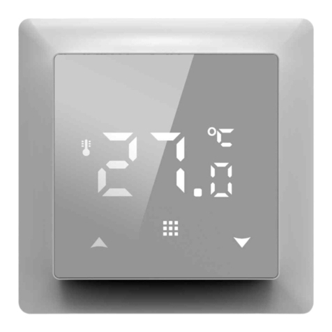
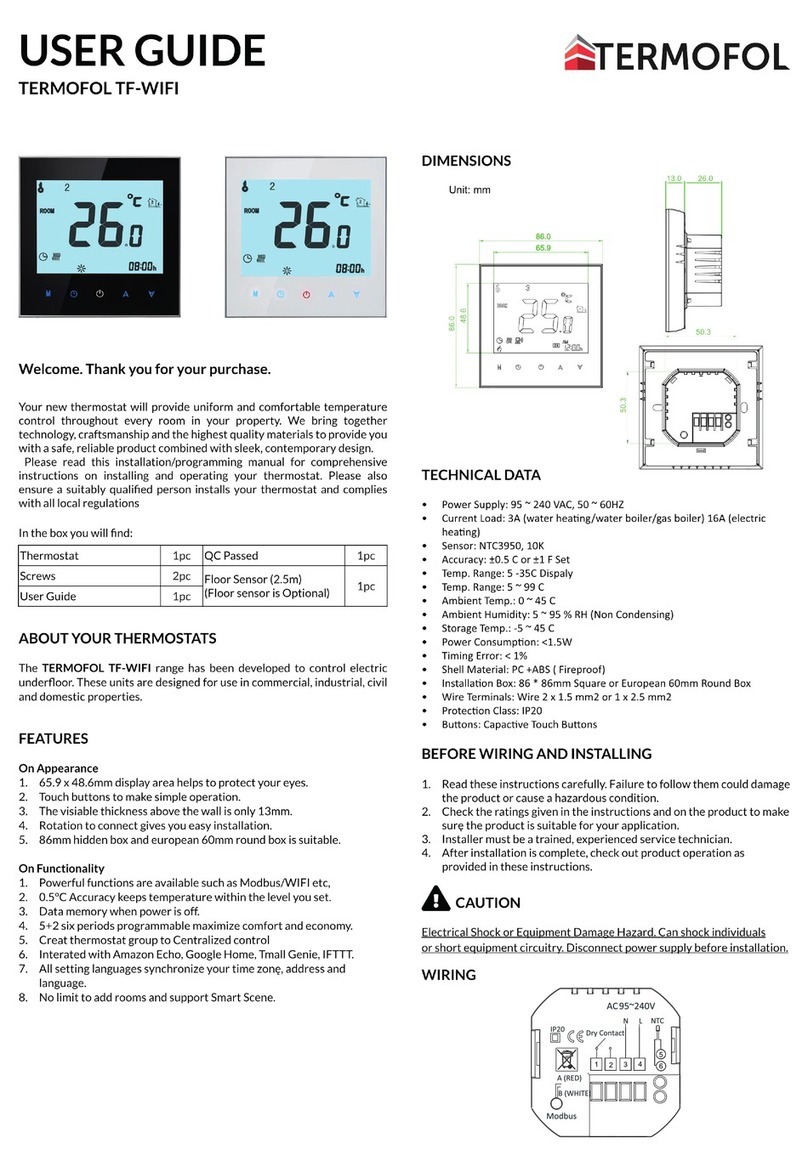
TERMOFOL TF-H6 WIFI User manual

ikona funkce WiFi
ikona připojení Cloud
01 – manuální režim: Ruční nastavení teploty 02 – automatický režim, nastavení týdenního harmonogra-
mu práce zařízení s rozlišením na 6 topných období během dne 03 – Holiday Mode (prázdninový režim)
– nastavení stálé teploty na určitý počet dní.
Nastavení pracovního režimu:
Stiskněte na min. 3 sekundy , následně pomocí tlačítek zvolte možnost 01, 02 nebo 03. Potvrďte
volbu stisknutím tlačítka .
Programování týdenního harmonogramu:
Z výroby je nastaven režim harmonogramu 5+2.
Následující tabulka znázorňuje výrobně nastavený cyklus dne.
Programování topných období během dne:
Stiskněte na 3 sekundy --> zvolte 02 --> stiskněte --> nastavte hodinu zahájení práce P1 --> potvrďte
stisknutím --> nastavte teplotu období P1 --> potvrďte stisknutím .
NÁVOD K OBSLUZE A KONFIGURACI TERMOSTATU
TERMOFOL TF-H6 WIFI
CHARAKTERISTIKA A TECHNICKÉ ÚDAJE
Děkujeme za nákup našeho výrobku. Pevně věříme, že budete s používáním termostatu TERMOFOL
TF-H6 WIFI spokojeni. Jedná se o plnohodnotný regulátor pro topné instalace a zařízení, který poskytuje
nejvyšší komfort obsluhy a přesné a užitečné funkce, které Vám umožní získat plnou kontrolu nad klima-
tem v místnosti. Níže se nachází displej termostatu a jeho základní technické parametry.
Napětí: 230 V AC 50/60 Hz • Barva: Bílá • Vnitřní čidlo teploty vzduchu: NTC • Vnější čidlo teploty vzduchu: NTC • Maximál-
ní intenzita přepínaného proudu: 16 A • Rozsah programované teploty: 1÷70 °C • Výrobní rozsah programované teploty:
5÷35 °C • Přesnost: ±0.5 °C • Vnější rozměry (bez rámečku): 55 mm x 55 mm • Vnější rozměry (s rámečkem): 82 mm x 82
mm (dostupný modulární systém) • Stupeň krytí IP31
INSTALACE TERMOSTATU, ELEKTRICKÉ ZAPOJENÍ
TERMOFOL TF-H6 je moderní, programovatelný regulátor, vybavený LED ovládacím panelem, který je ur-
čen k ovládání elektrických topných systémů. Termostat odečítá teplotu z vnitřního a vnějšího teplotního
čidla, které je dodáváno v sadě. Díky funkci WiFi a doporučené aplikaci výrobce TERMOFOL SMART lze
spravovat dohled nad topnou instalací mobilním zařízením. Před montáží, demontáží, čištěním, prová-
děním prohlídek, změnou kongurace vždy odpojte termostat od zdroje napájení, např. odpojte napá-
jecí vedení v elektrickém rozváděči. Před zahájením instalace termostatu se seznamte s celým obsahem
tohoto návodu k obsluze. Na území ČR musí elektrické zapojení termostatu provést elektrikář s osvěd-
čením o odborné způsobilosti v elektrotechnice dle vyhl. č. 50/1978 Sb. Elektrická instalace, která napájí
termostat, musí splňovat požadavky obsažené v nařízení Ministerstva infrastruktury a stavebnictví o
technických podmínkách, které musí splňovat budovy a jejich lokalizace (Sb. z. ze 7. června 2019, pol.
1065), včetně referenčních norem.
Obr. 1. Popis svorkovnice termostatu Obr. 2. Demontáž termostatu
Termostat je určen k montáži v elektrické připojovací krabici ø 60 mm. Za účelem jeho instalace do elek-
trické krabice a elektrického zapojení je nutné velmi jemně (tak, aby nedošlo k přetržení spojovací pásky)
otevřít jeho plášť – sejmout část s displejem v souladu s postupem znázorněným na Obr. 2 výše. Umístění
termostatu je nutné naplánovat v místě, které není vystaveno slunečnímu záření. Obr. 1 znázorňuje
svorkovnici termostatu, která slouží k zapojení zařízení do elektrické sítě. Neutrální kabel (N) přívodního
vedení se zapojuje do svorky označené číslem 2, fázový kabel (L) se zapojuje do svorky označené číslem
1. Topné zařízení (rohož, topná fólie) se zapojuje do svorek svorkovnice náležitě: neutrální kabel (N1)
napájení topného zařízení se zapojuje do svorky označené číslem 3, fázový kabel (L1) do svorky označené
číslem 4. Vnější teplotní čidlo NTC je nutné zapojit do svorek označených čísly 6 a 7, přičemž polarita
nemá význam. Po dokončení instalace a zhotovení elektrického zapojení je nutné provést konguraci
systému v souladu s dalším bodem tohoto návodu.
OVLÁDÁNÍ – POPIS FUNKCE OVLÁDACÍCH TLAČÍTEK
Níže je prezentována gracká identikace tlačítek ovládacího panelu (displeje) termostatu. Tato tlačítka
jsou multifunkční, tj. v závislosti na stavu práce termostatu a různé délce přidržení tlačítka lze zadávat
různé příkazy. Níže se nachází popis tlačítek a funkcí termostatu.
Tlačítko zapnout/vypnout. Ve vypnutém stavu způsobí stisknutí tohoto tlačítka zapnutí ter-
mostatu. Pokud je termostat zapnutý, stisknutí tohoto tlačítka způsobí zobrazení hodin na dis-
pleji. Za účelem vypnutí termostatu je nutné toto tlačítko stisknout a držet nejméně 3 sekundy.
Tlačítko menu slouží ke změně pracovního režimu termostatu z manuálního na automatický
nebo prázdninový (holiday mode) během práce termostatu. Pokud termostat pracuje v prázd-
ninovém (holiday mode) nebo automatickém režimu, stisknutí tohoto tlačítka způsobí aktiva-
ci manuálního režimu a možnost změny zadané teploty vzduchu. V zapnutém stavu způsobí
stisknutí a přidržení tohoto tlačítka (min. 5 sekund) vyvolání funkce úpravy hodin a data a pro-
gramování harmonogramu. V tomto případě toto tlačítko slouží také k potvrzování zadaných
změn a parametrů harmonogramu. Ve vypnutém stavu způsobí stisknutí a přidržení tohoto
tlačítka (min. 5 sekund) aktivaci průvodce pokročilými funkcemi termostatu.
Tlačítko zmenšujícího kurzoru. Ve stavu zapnutého termostatu stisknutí a přidržení toho-
to tlačítka na více než 3 sekundy zapíná a vypíná blokaci tlačítek, tzv. „child lock“. Jednotlivé
stisknutí zobrazí hodnotu teploty zadané v manuálním režimu, opakované stisknutí tlačítka
snižuje její hodnotu.
Tlačítko zvětšujícího kurzoru. Ve stavu zapnutého termostatu stisknutí a přidržení tohoto tlačít-
ka na více než 3 sekundy umožňuje odečet teploty měřené vnějším NTC teplotním čidlem.
Jednotlivé stisknutí zobrazí hodnotu teploty zadané v manuálním režimu, opakované stisknutí
tlačítka zvyšuje její hodnotu.
Pracuje-li termostat v režimu automatického harmonogramu, tlačítka umožňují dočasnou
úpravu teploty pro aktuálně termostatem realizovaný časový úsek automatického harmonogramu.
IKONY DISPLEJE – SPECIFIKACE
ikona společně s číslem od 1 do 6 in-
dikuje aktuálně realizovaný program
(období dne)
ikona indikuje aktuální den týdne v roz-
sahu od 1 do 7
ikona indikuje aktivitu blokace tlačítek
(child lock)
ikona indikuje spuštění funkce protim-
razové ochrany
ikona indikuje práci termostatu v
dočasném manuálním režimu v
rámci aktuálního
ikona potvrzuje práci termostatu v reži-
mu automatického harmonogramu
ikona potvrzuje práci termostatu
v manuálním režimu
ikona potvrzuje zapnutí topného
zařízení termostatem
ikona indikuje aktivaci prázdninového
režimu (holiday mode)
ikona indikuje aktivaci funkce
otevřeného okna
KONFIGURACE ZÁKLADNÍCH PARAMETRŮW
1
IP31
2 3 4 5 6 7
P1 P2 P3 P4 P5 P6
Budíček Odchod z domu Návrat domů Odchod z domu Návrat domů Spánek
6:00 20 °C 8:00 15 °C 11:30 15 °C 13:30 15 °C 17:00 15 °C 22:00 15 °C
PROGRAMOVÁNÍ POKROČILÝCH FUNKCÍ TERMOSTATU
Následující tabulka obsahuje přehled pokročilých funkcí a programovatelných parametrů termostatu.
Pro přístup do pokročilých nastavení je nutné vypnout termostat stisknutím tlačítka na déle než 3
sekundy. Následně přidržet tlačítko nejméně 5 sekund, do doby rozsvícení displeje termostatu. Jed-
notlivá stisknutí tlačítka přepínají mezi dalšími funkcemi/parametry a úprava hodnoty dané funkce/
parametru se provádí pomocí tlačítek <>. Přechodem do další funkce/parametru se ukládá nastavení
předchozí.
Č. Druh funkce / parametru Rozsah hodnoty parametru / funkce Výrobní
nastavení
1Kalibrace čidla teploty vzduchu -9 °C ÷ 9 °C -1 °C
2 Hystereze čidla teploty vzduchu 0.5 °C ÷ 2,5 °C 1 °C
3 Hystereze vnějšího čidla teploty 1 °C ÷ 9 °C 2 °C
4Volba teplotních čidel – způsobu
kontroly teploty
N1: pouze vnitřní teplotní čidlo zapnuté
N2: pouze vnější teplotní čidlo zapnuté
N3: zapnuté vnitřní i vnější teplotní čidlo – udržování za-
dané teploty vzduchu a kontrola teploty topného zařízení
N1
5 Blokace tlačítek 0: částečná blokace / 1: úplná blokace 0
6Omezení maximální teploty
vnějšího čidla
20 °C ÷ 70 °C Pozor: nastavení hodnoty pod 20 °C způsobí
vypnutí této funkce! 29 °C
7Omezení minimální teploty
vzduchu
1 °C ÷ 10 °C Pozor: nastavení hodnoty nad 10 °C způsobí
vypnutí této funkce! 5 °C
8Minimální hodnota
programované teploty 1 °C ÷ 10 °C 5 °C
9Maximální hodnota
programované teploty 20 °C ÷ 70 °C 35°C
AFunkce odstranění vodního
kamene (pro vodní kotle) 0: vypnutá / 1: zapnutá 0
BFunkce paměti stavu zařízení
před zánikem napětí
0: Zařízení přijme svůj stav z doby před zánikem napětí
1: Zařízení zůstává po obnovení napájení vypnuté
2: Zařízení se po obnovení napájení zapne 0
CTyp harmonogramu
automatické práce
(podle dnů týdne) 0: 5+2 dny / 1: 6+1 den / 2: 7 dní 0
DPohotovostní režim – kongura-
ce parametrů displeje
0: v režimu standby se nic nezobrazuje
1: v režimu standby se zobrazuje teplota
2: zobrazuje se teplota - v režimu standby vyšší jas 2
E Obnova výrobního nastavení Po zvolení této funkce přidržte déle než 5 sekund tlačítko Ao
FFunkce detekce otevřeného
okna (denice min. tepl.) 10°C ÷ 20 °C 10 °C
HDoba realizace funkce detekce
otevřeného okna 10 min ÷ 20 min 10 min
Hystereze vnějšího čidla – dodatečná informace: limit hodnoty teploty měřené vnějším čidlem činí 29 °C
pro výrobní nastavení pokročilých funkcí (bod 4), výrobní hodnota hystereze vnějšího čidla (bod 3) činí 2
°C. Pokud teplota stoupne na 29 °C, termostat přestane napájet ovládané topné zařízení a upozorní na
alarm vysoké teploty zobrazením blikajícího symbolu . Pokud teplota měřená vnějším čidlem klesne
na 27 °C, termostat znovu začne napájet ovládané topné zařízení a symbol přestane blikat (pouze v
případě, že je teplota vzduchu v místnosti nižší než zadaná).
Kódy chyb zobrazované termostatem. Je nutné vybrat správnou konguraci vnitřního a vnějšího teplot-
ního čidla v bodě 4 pokročilého nastavení. Chybná volba nebo porucha čidla (havárie) způsobí zobrazení
komunikátu o chybách na displeji. Zobrazení komunikátu „E1“ znamená poruchu vnitřního teplotního či-
dla, zobrazení komunikátu „E2“ znamená poruchu vnějšího teplotního čidla. Termostat nebude do doby
odstranění poruchy napájet ovládané topné zařízení!
Holiday Mode (prázdninový režim): nastavení prázdninového režimu
Stiskněte na 3 sekundy --> zvolte 03 --> stiskněte --> nastavte počet dní --> potvrďte stisknutím
--> nastavte zadanou teplotu --> potvrďte stisknutím .
Nastavení hodin:
Stiskněte na 3 sekundy --> zvolte 01 --> stiskněte --> nastavte aktuální hodinu --> potvrďte stisknutím
--> nastavte aktuální den týdne 1 pro pondělí, 2 pro úterý atd. --> potvrďte stisknutím .

The basic conguration of the thermostat includes setting the time and date (in the form of the number
of the day of the week), and selecting the operation mode from the available 3 modes: manual, automa-
tic and holiday mode.
Setting the time and date is done with the thermostat switched on. Hold the button pressed for at
least 3 seconds and then use the buttons to select option 01 and conrm the selection by pres-
sing the button . Minute, hour and day of the week are selected by an approval to be edited of the
successive variables by pressing the button in order to edit the selected variable and conrm the
selection, as well as by pressing the buttons . Programming the schedule is also performed with
the thermoregulator switched on. Press and hold the button for at least 3 seconds, then use the but-
tons to select option 02 and conrm by pressing the button . The next program – a time period
of day, minutes, hours - is selected by means of approving for editing, as well as by pressing the button in
order to edit the selected variable and approving it upon setting the proper value using the buttons .
OPERATING AND CONFIGURATION MANUAL
FOR THE THERMOFOL TF-H6 WIFI THERMOSTAT
CHARACTERISTICS AND TECHNICAL DATA
Thank you for purchasing our product. We hope that you will enjoy using the TERMOFOL TF-H6 WIFI ther-
moregulator. It is a fully functional controller of installations and heating devices providing the highest
comfort of use, as well as precise and useful functions that will allow you to fully control the climate in
your rooms. The display of the thermoregulator and its basic technical parameters are presented below.
Supply voltage: 240V AC 50/60 Hz • Colour: White – Built-in air temperature sensor: NTC • External oor air temperature
sensor: NTC (optional) • Maximum switched amperage: 16A • Programmable temperature range: 1÷70 °C • Factory
programmed temperature range: 5÷35 °C • Accuracy: ±0.5 °C • External dimensions (without frame): 55 mm x 55 mm •
External dimensions (with frame): 82 mm External dimensions (with frame): 82 mm x 82 mm (modular system available)
• Additional functions: Wi-Fi • IP31
THERMOSTAT INSTALLATION, ELECTRIC CONNECTIONS
The TERMOFOL TF-H6 WIFI is a modern, programmable thermoregulator with LED control panel inten-
ded for controlling electric heating systems. Thermoregulator works with a built-in NTC temperature
sensor and an external oor NTC temperature sensor, which is included in the kit along with the ther-
moregulator. Wi-Fi function and the manufacturer’s dedicated TERMO-FOL SMART application make it
possible to supervise the heating installation in the mobile manner. Prior to its installation, disassembly,
cleaning, inspection or change of the conguration, always disconnect the thermoregulator from the
power source, e.g., by switching o the power line in the electric switchboard. Read the entire contents
of this manual before installing the thermoregulator. In the territory of the Republic of Poland, the elec-
tric connections of the thermoregulator should be made by an electrician holding a valid SEP license for
electric installations up to 1 kV. The electric installation supplying the thermoregulator should meet the
requirements specied in the Regulation of the Minister of Infrastructure and Construction on technical
conditions to be met by buildings and their location (Journal of Laws of 7 June 2019, item 1065) along
with reference.
Figure 1. Description of the thermoregulator terminal block Figure 2. Disassembly of the thermoregulator
The thermoregulator is designed for the installation in a 60 mm electric installation box. For the purpose
of the installing, it in the installation box and making the electric connections, you should open its ho-
using very gently (so as not to break the connection tape) by removing the display unit according to the
instructions in Figure 2 above. The installation of the thermoregulator should be planned in a place not
exposed to the sunlight. Figure 1. shows the thermoregulator terminal block used to make the electric
connections. The power supply line of the thermoregulator is connected to the terminals of the ther-
moregulator terminal block. The neutral wire (N) of the power supply line is connected to the terminal
marked with number 2, and the phase wire (L) to the terminal marked with number 1. The heating device
(heating mat, heating lm) is connected to the terminals of the terminal block respectively, the neutral
wire (N1) of the heating device power supply line is connected to the terminal marked with number 3.
The external oor NTC temperature sensor should be connected to the terminals marked with numbers
6 and 7, where the polarity is irrelevant. Upon completing the installation and making the electric con-
nections, congure the system according to the next section of this manual.
CONTROLLING – DESCRIPTION OF FUNCTIONS OF CONTROL BUTTONS
The graphic identication of the thermoregulator control panel buttons (display) is presented below.
These buttons are multifunctional, i.e., depending on the operating status of the thermoregulator, and
by varying the duration of the touch, it is possible to give various commands to the thermoregulator.
The description of the buttons and the thermoregulator functions available with their use can be found
below.
Power ON/OFF button. In the thermostat o state, touching this button switches the thermo-
stat on. In the operating state of the thermostat, touching it displays the clock on the display of
this device. In order to turn the thermostat o, touch this button for at least 3 seconds.
Menu button is used to change the operating mode of the thermoregulator from the manual to
automatic schedule mode or holiday mode and vice versa while the thermostat is operating. If
the thermoregulator operates in the holiday mode or automatic schedule mode, touching this
button enables the manual mode and the possibility of changing the set air temperature. In the
operating status of the thermoregulator touching this button and holding down the button for
at least 5 seconds allows for enabling of the clock and date correction and schedule program-
ming functions. In this case the button is also used to conrm individual changes and schedule
parameters. When the thermoregulator is switched o, touching this button and holding the
touch for minimum 5 seconds activates the wizard of advanced functions of the thermoregu-
lator.
Cursor button for dialling down. When the thermoregulator is switched on, touching and hol-
ding it down for more than 3 seconds switches the child lock on and o. A single touch causes
that the temperature level set in the manual mode is displayed and repeated touches decrease
its value.
Cursor button for dialling up. When the thermoregulator is switched on, touching and holding
down for more than 3 seconds makes it possible to have a read-out of the temperature measu-
red by an external oor NTC temperature sensor. A single touch displays the temperature level
set in the manual mode, and repeated touches increase its value.
When the thermoregulator is operating in automatic schedule mode, the buttons allow for
a temporary temperature correction for the current period of the automatic schedule of the thermostat.
DISPLAY ICONS – SPECIFICATION
con with the numbers from 1 to 6 indica-
tes the currently operated programme
(period of one day and night -24 hrs.)
icon indicating the current day of the
week within the range from 1 to 7
icon indicating enabling the child lock
icon indicating enabling the anti-freeze
function
cons indicating the operation of the
thermoregulator in a temporary
mode within the current mode
icon conrming the thermostat opera-
tion in the automatic schedule mode
icon conrming the thermostat opera-
tion in the manual mode
icon conrming power supply to the
heating device by the thermostat
icon indicating enabling the holiday
mode
icon indicating the thermostat opera-
tion in the holiday mode
CONFIGURATION OF BASIC PARAMETERS (TIME, OPERATION MODE)
1
IP31
2 3 4 5 6 7
P1 P2 P3 P4 P5 P6
Wake - up Leaving home Returning home Leaving home Returning home Sleep
6:00 20 °C 8:00 15 °C 11:30 15 °C 13:30 15 °C 17:00 15 °C 22:00 15 °C
The holiday mode is enabled when the thermoregulator is turned on. Press and hold the button down
for at least 3 seconds, then use the buttons to select option 03 and conrm the selection by pres-
sing the button . The selection of days and temperature assigned to them is made by approving for
editing the successive variables, as well as by pressing the button to edit the selected variable and
conrming it upon setting the appropriate value using the buttons .
PROGRAMMING OF ADVANCED OPTIONS OF THERMOSTAT
The table below lists the advanced functions and programmable parameters of the thermostat. For
the purpose of getting an access the advanced settings, turn o the thermostat by pressing the but-
ton for more than 3 seconds. Then hold the button down for a minimum of 5 seconds until the
thermostat screen is illuminated. Single touches of the button switch between successive functions/
parameters and modication of the value of a given function/parameter is made using the buttons .
Moving to the next function/parameter saves the settings of the preceding one.
No. Type of function / parameter Range of parameter value / function option Factory
value
1 Calibration of air
temperature sensor -9 °C ÷ 9 °C -1 °C
2Hysteresis of air
temperature sensor 0,5 °C ÷ 2,5 °C 1 °C
3Hysteresis of external oor
temperature sensor 1 °C ÷ 9 °C 2 °C
4
Selection of temperature
sensors – Selection
temperature control method
N1: only built-in temperature sensor is ON only.
N2: only external oor temperature sensor is ON.
N3: built-in and external oor temperature sensors are ON
– maintaining the set air temperature with control of the
heating device temperature
N1
5 Button locking 0: partial locking / 1: full locking 0
6Limitation of maximum tempe-
rature of external oor sensor
20 °C ÷ 70 °C Note: setting a value below 20 °C will disable
this function! 29 °C
7Limitation of minimum
air temperature
1 °C ÷ 10 °C Note: setting a value above 10 °C will disable
this function! 5 °C
8Minimum value of programmed
temperature 1 °C ÷ 10 °C 5 °C
9Maximum value of program-
med temperature 20 °C ÷ 70 °C 35°C
ADecalcication function
(for water boilers) 0: enabled / 1: disabled 0
B
Memory function of device
status prior to a power supply
failure
0: Device restores its state prior to a power failure
1: Device remains OFF after power supply returns
2: Device remains ON after power supply returns
0
CType of automatic operation
schedule (by weekdays) 0: 5+2 days / 1: 6+1 days / 2: 7 days 0
DSleep mode – conguration of
display parameters
0: nothing is displayed in standby mode
1: temperature is displayed in standby mode
2: temperature is displayed – higher brightness in standby
mode
2
E Restoration of factory settings Hold down the button for more than 5 seconds after
selecting this option Ao
F
Open window detection func-
tion (range of temperature
function enable)
10°C ÷ 20 °C 10 °C
HPeriod of execution open
window detection function 10 min ÷ 20 min 10 min
Hysteresis of the external oor sensor – additional information: the limit of temperature value measured
by the external oor sensor is of 29 °C for the factory setting of advanced options (section 6), and the fac-
tory value of external oor sensor hysteresis (section 3) is of 2 °C. When the temperature rises to 29 °C,
the thermostat stops supplying the controlled heating device and reminds you of the high temperature
alarm by displaying the ashing symbol . If the temperature measured by the external oor sen-
sor decreases to 27 °C, the thermostat will start supplying the controlled heating device again and the
symbol will stop ashing (only if the air temperature in the room is lower than the set temperature).
Error codes displayed by the thermostat. A correct conguration of the built-in and external oor tem-
perature sensors must be provided according to section 4 related to the advanced options. An incorrect
selection or a sensor malfunction (failure) will cause an error message to be displayed on the screen.
Displaying the message with the following content: ‘E1’ means a malfunction of the built-in temperature
sensor, while displaying a message of the following content ‘E2’ means that the external oor tempera-
ture sensor has failed. The thermostat will not supply power to the controlled heating device until the
fault has been rectied!
Wi-Fi function icon
Cloud connection icon

PŘIPOJENÍ TERMOSTATU K WIFI
A OBSLUHA APLIKACE TERMOFOL SMART
VOLBA A INSTALACE APLIKACE
Termostat spolupracuje výhradně se sítěmi WiFi 2,4 Ghz. Ovládání termostatu probíhá prostřednictvím
aplikace TERMOFOL SMART dostupné pro Android i iOS. Za účelem připojení termostatu k místní WiFi
síti je nutné si stáhnout na mobilní zařízení aplikaci TERMOFOL SMART. Lze k tomu použít následující QR
kódy:
Android: IoS:
Staženou aplikaci nainstalujte na mobilní zařízení, zapněte službu lokalizace a spojení WiFi zařízení se
sítí, ke které budete připojovat termostat. Napište si heslo k této síti, protože jej budete potřebovat v
další fázi kongurace.
REGISTRACE ÚČTU V APLIKACI
Pro používání aplikace je nutné založit uživatelský účet (registrovat se v aplikaci). Za tímto účelem spusťte
aplikaci a v prvním okně zvolte možnost „registrovat“. V dalším okně
zadejte zemi instalace, zadejte e-mail, na který bude odeslán ověřovací kód. Po vyplnění těchto údajů je
nutné ze zaslané e-mailové zprávy přepsat ověřovací kód do aplikace v dalším okně registrace. Proces re-
gistrace končí zadáním hesla k vytvořenému účtu, kterým se budete přihlašovat ke svému účtu v aplikaci.
Registrace je dokončena a nyní můžete přejít k přidání zařízení – připojení termostatu.
PŘÍPRAVA TERMOSTATU NA PŘIPOJENÍ K WIFI SÍTI
Před spuštěním procesu přidávání termostatu v aplikaci je nutné zapnout funkci WiFi a synchronizaci
Cloud. Za tímto účelem zapněte termostat přidržením stisknutého tlačítka po dobu nejméně 3 se-
kund. Následně současně přidržte stisknutá tlačítka a po dobu od 5 do 20 sekund, do doby, kdy se
v pravém dolním rohu displeje, nad tlačítkem , zobrazí blikající
symboly: . Termostat je připraven na připojení k WiFi síti.
PŘIPOJENÍ TERMOSTATU V APLIKACI
Když máte připravený termostat, spusťte aplikaci TERMOFOL SMART a po přihlášení do aplikace zvolte
v hlavním okně funkci „přidat zařízení“.
V dalším okně zvolte ikonu „termostat“, v dalším okně označte možnost „potvrdit rychlé blikání ikony
wi“ a zvolte „next“. V dalším okně zadejte přístupové heslo do WiFi sítě, ke které je připojen termostat,
a potvrďte tlačítkem „další“. Proces připojení probíhá plně automaticky a jeho postup můžete sledovat
v okně zobrazujícím postup času a na 3bodové ose fází nastavování připojení. Po dokončení procesu
připojení ukazatel dosáhne 3. úrovně, poté se automaticky zobrazí okno s informací o úspěšném přidání
zařízení, ve kterém lze případně provést změnu názvu tohoto zařízení, pod kterým bude zobrazováno v
aplikaci. Celý proces potvrďte kliknutím na nápis „Dokončeno“, který se nachází v pravém horním rohu
okna. V okně samotného termostatu budou doposud blikající symboly svítit nepřerušovaně.
Potvrzuje to také, že celý proces připojení proběhl úspěšně a je možné přejít k ovládání a konguraci
termostatu pomocí aplikace.
Za účelem výběru zařízení, které má být ovládáno, klikněte na pruh s jeho názvem. Otevře se okno
daného zařízení. Jsou v něm zobrazeny informace o aktuální teplotě vzduchu, stavu zařízení – plamínek
signalizuje stav práce, čili napájení topného zařízení. Pomocí půlkulatého šoupěte, nebo bezprostředně
tlačítky „+“ a „-“, můžete měnit hodnotu zadané teploty. Pomocí tlačítek, která se nacházejí na dolním
pruhu, můžete náležitě: – zapínat a vypínat termostat , – provádět přepínání pracovního režimu
z manuálního na automatický a opačně, – blokovat a odblokovat ovládací tlačítka, a – měnit po-
kročilé nastavení a parametry termostatu. Návrat k hlavnímu oknu aplikace probíhá stisknutím příkazu
„back“, který se nachází v levém horním rohu okna aplikace.
Po zvolení tlačítka se zobrazí okno „Setting”. Obsahuje seznam nastavení a pokročilých funkcí,
uspořádaných ve formě vodorovných pruhů popsaných názvem dané funkce, včetně informace o hod-
notě každé funkce prezentované u pravého okraje daného řádku. Za účelem provedení změny daného
parametru/funkce je nutné kliknout na znak „>”, který se nachází na konci řádku funkce, kterou chcete
upravit. Před provedením úpravy budete vyzváni k potvrzení oprávnění zadáním správcovského hesla,
které je z výroby nastaveno na „123456“. Chcete-li tedy například změnit konguraci teplotních čidel,
zvolte řádek „Temperature sensor“, poté z rozbaleného kontextového menu v dolní části okna vyberte
např. možnost vnitřní čidlo „Int. Sensor” a klikněte na „Done”.
ZMĚNA KONFIGURACE TEPLOTNÍCH ČIDEL
Po zvolení tlačítka se zobrazí okno „Setting”. Obsahuje seznam nastavení a pokročilých funkcí,
uspořádaných ve formě vodorovných pruhů popsaných názvem dané funkce, včetně informace o hod-
notě každé funkce prezentované u pravého okraje daného řádku. Za účelem provedení změny daného
parametru/funkce je nutné kliknout na znak „>”, který se nachází na konci řádku funkce, kterou chcete
upravit. Před provedením úpravy budete vyzváni k potvrzení oprávnění zadáním správcovského hesla,
které je z výroby nastaveno na „123456“. Chcete-li změnit hodnotu maximální teploty topného zařízení,
měřené vnějším teplotním čidlem, zvolte řádek „High temperature protection“, poté z rozbaleného kon-
textového menu v dolní části okna vyberte – posunutím nahoru nebo dolů – konkrétní úroveň teploty,
např. 29 °C, a klikněte na „Conrm“.
ZMĚNA HODNOTY MAXIMÁLNÍ TEPLOTY VNĚJŠÍHO ČIDLA
Po zvolení tlačítka se zobrazí okno „Setting”. Zvolte řádek „Program type”, nastavte druh harmo-
nogramu 5+2/6+1/7 dní a potvrďte volbu tlačítkem „Done”. Poté zvolte funkci „Weekly program setting”
a denujte hodnoty teplot pro vybraná období dne, upravte libovolně jak hodnotu teploty, tak mezní
hodiny denující začátek a konec dalších období dne pro zvolené týdenní schéma.
PROGRAMOVÁNÍ HARMONOGRAMU AUTOMATICKÉ PRÁCE

CONNECTING THE THERMOSTAT TO THE WIFI NETWORK
OPERATING THE TERMOFOL SMART APPLICATION
CHOOSING PLATFORM AND INSTALLING THE APPLICATION
The thermostat works only with 2.4 GHz WiFi networks. The thermostat is controlled via the TERMOFOL
SMART application available for Android and IoS platforms. In order to carry out the process of con-
necting the thermostat to the local WiFi network, download the TERMOFOL SMART application to your
mobile device using the following QR codes:
Android: IoS:
Install the downloaded application on the mobile device and turn on the location services and WiFi
connection of the device to the network to which the thermostat will be connected. Make a note of the
password for this network as it will be needed in the further conguration process.
ACCOUNT REGISTRATION IN THE APP
In order to use the application, you must create a user account (register in the application). To do this,
run the application, and on the rst screen, select the „Sign up” option. On the next screen
indicate the country of installation, and enter the e-mail address to which the verication code will be
sent. After completing this data, read the verication code from the content of the e-mail message re-
ceived and complete it on the next application registration screen. We nish the registration process by
setting a password for our account, which we will log into our account in the application from now on.
The registration is complete and we can proceed to adding the device - connecting the thermostat.
PREPARING THE THERMOSTAT FOR CONNECTION TO THE WIFI NETWORK
Before starting the process of adding a thermostat in the application, turn on the WiFi function and
Cloud synchronization. To do this, turn on the thermostat by holding down the buton for at least 3
seconds. Then, simultaneously hold down the and buttons for 5 to 20 seconds until the ashing
symbols above the buton appear in the lower right corner of the screen: . The thermostat is
ready to connect to the WiFi network.
CONNECTING THE THERMOSTAT IN THE APPLICATION
Having the thermostat ready, run the TEMOFOL SMART application and after logging into the application
on the main screen, select the add device function.
On the next screen, select the thermostat icon, and on the next screen, select the „conrm fast blinking
wi icon” option and select the „next” button. On the next screen, enter the access password of the wi
network to which the thermostat is connected and conrm by selecting the „next” button. The connec-
tion process is fully automatic, and its progress can be tracked on the screen showing the progress of
time and on the 3-point axis of the subsequent stages of establishing the connection. After completing
the connection process, the progress indicator will reach level 3, after which a screen will automatically
appear informing about the successful addition of the device and allowing for a possible change of the
name of the device under which it will be displayed in the application. We approve the entire process by
clicking on the „Done” in the upper right corner of the application screen. On the thermostat’s screen you
will notice that the previously ashing symbols: , are displayed in a constant manner.
This additionally conrms that the entire connection process was successful and we can go to control
and conguration of the thermostat with the participation of the application.
To select a device to control, click on the bar with its name, which starts the device screen. It displays
information about the current air temperature, device status - the ame indicates the operating status,
i.e. power supply to the heating device. With the semicircular slider or directly with the buttons „+” and
„–” we can change the value of the set temperature. Using the buttons on the lower bar, we can: –
turn the thermostat on and o , – switch the operating mode from manual to automatic and vice
versa, – lock and unlock the control buttons, and – change the options and advanced parameters
of the thermostat. We return to the main application window by pressing the „back” command located
in the upper left corner of the application screen.
After selecting the buton , the „Setting” screen appears. It contains a list of advanced settings and
functions arranged in the form of horizontal bars described with the name of a given function, along with
information about the current value of each function presented at the right edge of a given row. In order
to change a given parameter / function, click on the „>” sign at the end of the line of the function whose
setting you want to modify. Before editing, you will be asked to conrm the permissions by entering the
administrator password, which is set to „123456” by default. And so, if you want to change, for exam-
ple, the conguration of temperature sensors, select the „Temperature sensor” line and then select, for
example, the internal sensor „Int. Sensor” and click „Done”.
CHANGING THE CONFIGURATION OF TEMPERATURE SENSORS
After selecting the buton , the „Setting” screen appears. It contains a list of advanced settings and
functions arranged in the form of horizontal bars described with the name of a given function, along with
information about the current value of each function presented at the right edge of a given row. In order
to change a given parameter / function, click on the „>” sign at the end of the line of the function whose
setting you want to modify. Before editing, you will be asked to conrm the permissions by entering the
administrator password, which is set to „123456” by default. If you want to change the value of the maxi-
mum temperature of the heating device measured by the external temperature sensor, select the „High
temperature protection” line, then select the context menu from the context menu at the bottom of the
screen by moving up or down a specic temperature level, e.g. 29 ° C and click „Conrm”.
CHANGING THE MAXIMUM TEMPERATURE OF THE OUTDOOR SENSOR
After selecting the buton , the „Setting” screen appears. Select the „Program type” line by setting the
type of schedule 5 + 2/6 + 1/7 days and conrm the selection with the „Done” button. Then select the
„Weekly program setting” function and dene the temperature values for the selected periods of the
day, modifying freely both the temperature value and the time limit that dene the beginning and end
of subsequent periods for the selected weekly schedule.
PROGRAMMING OF THE AUTOMATIC WORK SCHEDULE
Table of contents
Languages:
Other TERMOFOL Thermostat manuals
Popular Thermostat manuals by other brands
Emerson
Emerson 1F83H-21PR Installation and operating instructions

Honeywell
Honeywell RTH6300B installation guide
Mars
Mars 70812 Installation and operating instructions
Aube Technologies
Aube Technologies TH111GFCI-NP owner's manual
CLIMASET
CLIMASET Retro Series instruction manual
Geca
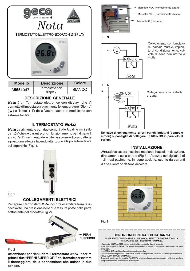
Geca Nota quick start guide
