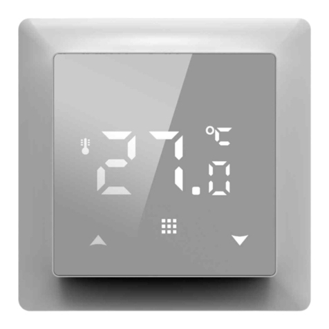
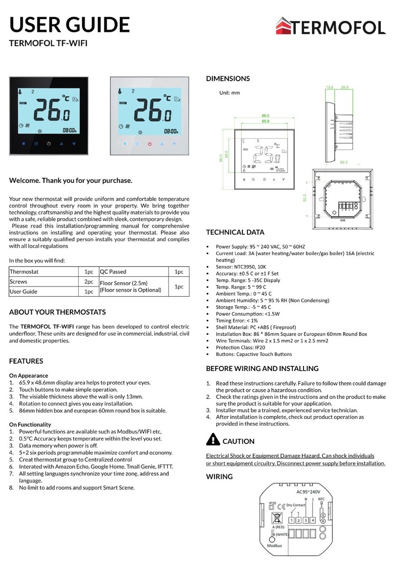
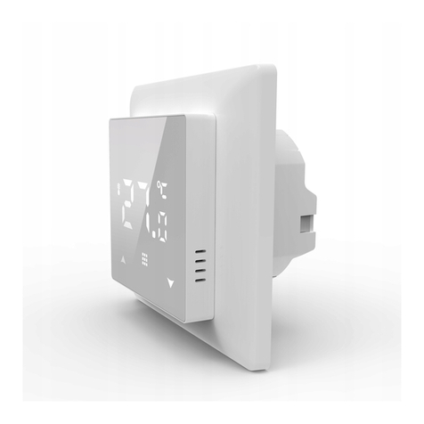
TERMOFOL TF-H6 User manual

01 – tryb manualny: Ręczne ustawienie temperatury 02 – tryb automatyczny, ustawienie tygodniowego
harmonogramu pracy urządzenia z podziałem na 6 okresów grzewczych w ciągu doby 03 – Holiday Mode
(Tryb Wakacyjny) – ustawienie stałej temperatury na określoną liczbę dni.
Ustawienie trybu pracy:
Naciśnij przez min. 3 sek. następnie z wykorzystaniem przycisków wybierz opcję 01, 02 lub
03. Zatwierdź wybór naciskając przycisk
Programowanie harmonogramu tygodniowego:
Fabrycznie wybrany tryb harmonogramu to 5+2. Poniższa tabela przedstawia fabryczny cykl dnia.
Programowanie okresów grzewczych w ciągu doby: Naciśnij przez 3 sek. --> wybierz 02 --> naciśnij
--> ustaw godzinę rozpoczęcia pracy P1 --> zatwierdź naciskając --> ustaw temperaturę okresu
P1 --> zatwierdź naciskając Powtórz czynność dla wszystkich okresów grzewczych P1-P6 następnie
powtórz schemat dla dni weekendowych przechodząc przez punkty P1-P6.
INSTRUKCJA OBSŁUGI I KONFIGURACJI TERMOSTATU
TERMOFOL TF-H6
CHARAKTERYSTYKA I DANE TECHNICZNE
Dziękujemy za zakup naszego produktu. Liczymy, że będziecie Państwo zadowoleni z korzystania z ter-
moregulatora TERMOFOL TF-H6. Jest to w pełni funkcjonalny sterownik instalacji i urządzań grzewczych
zapewniający najwyższy komfort obsługi oraz precyzyjne i użyteczne funkcje, które pozwolą Państwu w
pełni uzyskać kontrolę nad klimatem pomieszczeń. Poniżej przedstawiono wyświetlacz termoregulatora
oraz jego podstawowe parametry techniczne.
Napięcie zasilające: 230 V AC 50/60 Hz • Kolor: Biały • Wewnętrzny czujnik temp. powietrza: NTC • Zewnętrzny czujnik
temp. powietrza: NTC • Maksymalne natężenie przełączanego prądu: 16A • Zakres programowanej temp.: 1÷70 °C •
Fabryczny zakres programowanej temperatury: 5÷35 °C • Dokładność: ±0.5 °C • Wymiary zewnętrzne (bez ramki): 55
mm x 55 mm • Wymiary zewnętrzne (z ramką): 82 mm x 82 mm (dostępny system modułowy) • Stopień ochrony IP31
INSTALACJA TERMOSTATU, POŁĄCZENIA ELEKTRYCZNE
TERMOFOL TF-H6 to nowoczesny wyposażony w panel sterujący LED, programowalny termoregulator
przeznaczony do sterowania elektrycznymi systemami grzewczymi. Termoregulator odczytuje tempe-
raturę z wewnętrznego i zewnętrznego czujnika temperatury, który jest dołączony w zestawie. Przed
montażem, demontażem, czyszczeniem, dokonywaniem przeglądu, zmiany konguracji, zawsze odłącz
termoregulator od źródła zasilania, np. wyłączając linię zasilającą w rozdzielni elektrycznej.
Zapoznaj się z całą treścią niniejszej instrukcji przed rozpoczęciem instalacji termoregulatora. Na tere-
nie RP, połączeń elektrycznych termoregulatora musi dokonać elektryk posiadający czynne uprawnienia
SEP do robót elektroinstalacyjnych do 1 kV. Instalacja elektryczna zasilająca termoregulator powinna
odpowiadać wymogom określonym w Rozporządzeniu Ministra Infrastruktury i Budownictwa w sprawie
warunków technicznych jakim powinny odpowiadać budynki i ich usytuowanie [DZ.U. z 7 czerwca 2019,
poz. 1065] wraz z normami odniesienia.
Rysunek 1. Opis listwy zaciskowej termoregulatora Rysunek 2. Demontaż termoregulatora
Termoregulator przeznaczony jest do montażu w puszce elektrycznej ø 60 mm. W celu jego instalacji
w puszce elektrycznej i podłączeń elektrycznych należy bardzo delikatnie (tak by nie urwać taśmy połą-
czeniowej) otworzyć jego obudowę zdejmując zespół wyświetlacza zgodnie z instrukcją przedstawioną
na Rysunku 2. powyżej. Instalacja termoregulatora powinna być zaplanowana w miejscu nie narażonym
na kontakt z promieniami słonecznymi. Rysunek nr 1. przedstawia listwę zaciskową termoregulatora
służącą do wykonania podłączeń elektrycznych urządzenia z siecią elektryczną. Odpowiednio przewód
neutralny (N) linii zasilającej przyłączamy do zacisku oznaczonego numerem 2, a przewód fazowy (L) do
zacisku oznaczonego numerem 1. Natomiast urządzenie grzewcze (matę, folią grzewczą) podłączamy
do zacisków listwy odpowiednio: przewód neutralny (N1) zasilania urządzenia grzewczego przyłącza-
my do zacisku oznaczonego numerem 3, a przewód fazowy (L1) do zacisku oznaczonego numerem 4.
Zewnętrzny czujnik temperatury NTC należy przyłączyć do zacisków oznaczonych numerami 6 i 7, przy
czym biegunowość nie ma znaczenia. Po zakończeniu instalacji i wykonaniu połączeń elektrycznych nale-
ży dokonać konguracji systemu zgodnie z kolejnym punktem niniejszej instrukcji.
STEROWANIE – OPIS FUNKCJI PRZYCISKÓW STERUJĄCYCH
Poniżej przedstawiono identykację graczną przycisków panelu sterującego (wyświetlacza) termoregu-
latora. Przyciski te są multi-funkcjonalne, tzn. w zależności od stanu pracy termoregulatora, oraz różni-
cując czas utrzymywania dotyku możliwe jest wydawanie różnych komend termoregulatorowi. Poniżej
dokonano deskrypcji przycisków, oraz szczegółowo omówiono dostępne z ich udziałem funkcje termo-
regulatora.
Przycisk włącz/wyłącz. W stanie wyłączonym termostatu dotknięcie tego przycisku załącza ter-
mostat. W stanie pracy termostatu dotknięcie powoduje wyświetlenie zegara na wyświetlaczu
termostatu. W celu wyłączenia termoregulatora należy niniejszy przycisk dotknąć utrzymując
dotyk przez minimum 3 sek.
Przycisk menu służy do zmiany trybu pracy termoregulatora z manualnego na automatyczny
lub funkcję wakacyjną (holiday mode) w trakcie pracy termoregulatora. W przypadku gdy ter-
moregulator pracuje w trybie wakacyjnym (holiday mode) lub automatycznym, dotknięcie tego
przycisku powoduje uaktywnienie trybu manualnego i możliwość zmiany zadanej temperatury
powietrza. W stanie pracy termoregulatora dotknięcie tego przycisku przez min. 5 sek. pozwala
wywołać funkcje korekty zegara i daty oraz programowania harmonogramu. W tym przypadku
przycisk ten również służy do zatwierdzania poszczególnych wprowadzanych zmian i parame-
trów harmonogramu W stanie wyłączonego termoregulatora dotknięcie tego przycisku i utrzy-
manie dotyku przez min. 5 sek. uruchamia kreatora funkcji zaawansowanych termoregulatora.
Przycisk kursora zmniejszającego. W stanie załączonego termoregulatora dotknięcie i przytrzy-
manie przez ponad 3 sek. załącza i wyłącza blokadę przycisków tzw. „child lock”. Pojedyncze do-
tknięcie wyświetla poziom temperatury zadanej w trybie manualnym a wielokrotne dotknięcia
zmniejszają jej wartość.
Przycisk kursora zwiększającego. W stanie załączonego termoregulatora dotknięcie i przytrzy-
manie przez ponad 3 sek. umożliwia odczyt temperatury mierzonej przez zewnętrzny czujnik
temperatury NTC. Pojedyncze dotknięcie wyświetla poziom temperatury zadanej w trybie ma-
nualnym a wielokrotne dotknięcia zwiększają jej wartość.
W przypadku pracy termoregulatora w trybie automatycznego harmonogramu przyciski
umożliwiają czasową korektę temperatury dla wykonywanego przez termostat aktualnego okresu auto-
matycznego harmonogramu.
IKONY WYŚWIETLACZA – SPECYFIKACJA
ikona wraz z numerem od 1 do 6 wska-
zuje aktualnie wykonywany program
(okres doby)
ikona wskazująca aktualny dzień tygo-
dnia z zakresu od 1 do 7
ikona wskazująca aktywność blokady
przycisków (child lock)
ikona wskazująca uruchomienie funkcji
przeciw zamarzaniu
ikony wskazujące pracę termore-
gulatora tymczasowym trybie ma-
nualnym w ramach bieżącego
ikona potwierdzająca pracę termostatu
w trybie automatycznego harmonogra-
mu
ikona potwierdzająca pracę termostatu
w trybie manualnym
ikona potwierdzająca załączenie urzą-
dzenia grzewczego przez termostat
ikona wskazująca uruchomienie trybu
wakacyjnego (holiday mode)
ikona wskazująca aktywność funkcji
otwartego okna
KONFIGURACJA PODSTAWOWYCH PARAMETRÓW
1
IP31
2 3 4 5 6 7
P1 P2 P3 P4 P5 P6
Pobudka Wyjście z domu Powrót do
domu Wyjście z domu Powrót do domu Sen
6:00 20 °C 8:00 15 °C 11:30 15 °C 13:30 15 °C 17:00 15 °C 22:00 15 °C
PROGRAMOWANIE OPCJI ZAAWANSOWANYCH TERMOSTATU
Poniższa tabela zawiera zestawienie zaawansowanych funkcji i programowalnych parametrów termo-
statu. Aby uzyskać dostęp do ustawień zaawansowanych należy wyłączyć termostat poprzez naciśnięcie
przycisku przez ponad 3s. Następnie należy przytrzymać przycisk przez minimum 5s. do czasu
zapalenia się ekranu termostatu. Pojedyncze dotknięcia przycisku przełączają pomiędzy kolejnymi
funkcjami/parametrami a modykacja wartości danej funkcji/parametru dokonywana jest z użyciem
przycisków . Przejście do kolejnej funkcji/parametru zapamiętuje ustawienia poprzedzającej.
Nr Rodzaj funkcji / parametru Zakres wartości parametru / opcji funkcji Wartość
fabryczna
1 Kalibracja czujnika
temperatury powietrza -9 °C ÷ 9 °C -1 °C
2Histereza czujnika
temperatury powietrza 0.5 °C ÷ 2,5 °C 1 °C
3Histereza zewnętrznego
czujnika temperatury 1 °C ÷ 9 °C 2 °C
4Wybór czujników temperatury –
sposobu kontroli temperatury
N1: tylko wewnętrzny czujnik temperatury włączony
N2: tylko zewnętrzny czujnik temperatury włączony
N3: włączony wewnętrzny i zewnętrzny czujnik temperatury
– utrzymywanie zadanej temperatury powietrza z kontrolą
temperatury urządzenia grzewczego
N3
5 Blokada przycisków 0: blokada częściowa / 1: blokada pełna 0
6Ograniczenie maksymalnej tem-
peratury czujnika zewnętrznego
20 °C ÷ 70 °C Uwaga: ustawienie wartości poniżej 20 °C
spowoduje wyłączenie tej funkcji! 29 °C
7Ograniczenie minimalnej
temperatury powietrza
1 °C ÷ 10 °C Uwaga: ustawienie wartości powyżej 10 °C
spowoduje wyłączenie tej funkcji! 5 °C
8Minimalna wartość temperatury
programowanej 1 °C ÷ 10 °C 5 °C
9Maksymalna wartość
temperatury programowanej 20 °C ÷ 70 °C 35°C
AFunkcja odkamieniania
(dla kotłów wodnych) 0: wyłączona / 1: włączona 0
B
Funkcja pamięci stanu
urządzenia przed zanikiem
napięcia zasilającego
0 : U r z ą d z e n i e p r z y j m u j e s w ó j s t a n s p r z e d z a n i k u z a s i l a n i a
1 : U r z ą d z e n i e p o z o s t a j e w y ł ą c z o n e p o p o w r o c i e z a s i l a n i a
2: Urządzenie pozostaje włączone po powrocie zasilania
0
CTyp harmonogramu pracy
automatycznej (wg dni tygodnia) 0: 5+2 dni / 1: 6+1 dni / 2: 7 dni 0
DTryb uśpienia – konguracja
parametrów wyświetlacza
0 : n i c n i e w y ś w i e t l a n e w t r y b i e s t a n d b y
1 : w y ś w i e t l a n a t e m p e r a t u r a w t r y b i e s t a n d b y
2: wyświetlana tem. – wyższa jasność w trybie standby
2
EPrzywrócenie ustawień
fabrycznych
Przytrzymać przez ponad 5s przycisk po wyborze tej
opcji Ao
FFunkcja wykrywania otwartego
okna (określenie temp. min.) 10°C ÷ 20 °C 10 °C
HCzas wykonywania funkcji
wykrywania otwartego okna 10 min ÷ 20 min 10 min
P1 Zużycie energii elektr. w dniu
wczorajszym
XXX Kwh długo naciśnij strzałkę
co spowoduje wyzerowanie wyniku
P2 Łączne zużycie energii
elektrycznej
XXX Kwh długo naciśnij strzałkę
co spowoduje wyzerowanie wyniku
P3 Ustaw moc urządzenia
grzewczego XXXX W, Wpisz moc urządzenia pomiędzy 100-3500W 2000W
P4 Modbus IP adres komunikacji 01~FF 01
P5 Modbus prędkość transmisji
danych 0: 2400 1: 4800 2: 9600 0
Histereza czujnika zewnętrznego – dodatkowa informacja: limit wartości temperatury mierzonej przez
czujnik zewnętrzny wynosi 29 °C dla ustawień fabrycznych opcji zaawansowanych (pkt 6.), a fabryczna
wartość histerezy czujnika zewnętrznego (pkt 3.) wynosi 2 °C. Gdy temperatura wzrośnie do 29 °C, ter-
mostat przestanie zasilać sterowane urządzenie grzewcze i przypomni o alarmie wysokiej temperatury
wyświetlając migający symbol . Jeśli temperatura mierzona przez czujnik zewnętrzny spadnie do
27 °C termostat ponownie zacznie zasilać sterowane urządzenie grzewcze i symbol przestanie migać
(tylko w sytuacji gdy temperatura powietrza w pomieszczeniu jest niższa od zadanej).
Kody błędów wyświetlane przez termostat. Należy wybrać poprawną kongurację wbudowanego i ze-
wnętrznego czujnika temperatury w pkt 4. opcji zaawansowanych. Błędny wybór lub usterkę czujnika
(awaria) spowoduje wyświetlenie na ekranie komunikatu o błędach. Wyświetlanie komunikatu o treści
„E1” oznacza usterkę czujnika wewnętrznego temperatury, natomiast wyświetlanie komunikatu o treści
„E2” oznacza usterkę czujnika zewnętrznego temperatury. Termostat nie zasili sterowanego urządzenia
grzewczego do czasu usunięcia usterki!
Holiday Mode (Tryb Wakacyjny): ustawienie okresu wakacyjnego
Naciśnij przez 3 sek. --> wybierz 03 --> naciśnij --> ustaw ilość dni --> zatwierdź naciskając -->
ustaw zadaną temperaturę --> zatwierdź naciskając
Ustawienie zegara:
Naciśnij przez 3 sek. --> wybierz 01 --> naciśnij --> ustaw aktualną godzinę --> zatwierdź
naciskając --> ustaw aktualny dzień tygodnia 1 dla pon, 2 dla wt itd. --> zatwierdź naciskając
Włącz termostat, naciśnij i przytrzymaj + aby sprawdzić adres IP Modbus
Wyłącz termostat, naciśnij długo oraz aby przejść do zaawansowanej opcji P. Krótko naciśnij aby wybrać
pozycję, krótko naciśnij lub aby zmienić wartość.

The basic conguration of the thermostat includes setting the time and date (in the form of the number
of the day of the week), and selecting the operation mode from the available 3 modes: manual, automa-
tic and holiday mode.
Setting the time and date is done with the thermostat switched on. Hold the button pressed for at
least 3 seconds and then use the buttons to select option 01 and conrm the selection by pres-
sing the button . Minute, hour and day of the week are selected by an approval to be edited of the
successive variables by pressing the button in order to edit the selected variable and conrm the
selection, as well as by pressing the buttons . Programming the schedule is also performed with
the thermoregulator switched on. Press and hold the button for at least 3 seconds, then use the but-
tons to select option 02 and conrm by pressing the button . The next program – a time period
of day, minutes, hours - is selected by means of approving for editing, as well as by pressing the button in
order to edit the selected variable and approving it upon setting the proper value using the buttons .
OPERATING AND CONFIGURATION MANUAL
FOR THE THERMOFOL TF-H6 THERMOSTAT
CHARACTERISTICS AND TECHNICAL DATA
Thank you for purchasing our product. We hope that you will enjoy using the TERMOFOL TF-H6 ther-
moregulator. It is a fully functional controller of installations and heating devices providing the highest
comfort of use, as well as precise and useful functions that will allow you to fully control the climate in
your rooms. The display of the thermoregulator and its basic technical parameters are presented below.
Supply voltage: 240V AC 50/60 Hz • Colour: White • Built-in air temperature sensor: NTC • External oor air temperature
sensor: NTC (optional) • Maximum switched amperage: 16A • Programmable temperature range: 1÷70 °C • Factory
programmed temperature range: 5÷35 °C • Accuracy: ±0.5 °C • External dimensions (without frame): 55 mm x 55 mm •
External dimensions (with frame): 82 mm External dimensions (with frame): 82 mm x 82 mm (modular system available)
• IP31
THERMOSTAT INSTALLATION, ELECTRIC CONNECTIONS
The TERMOFOL TF-H6 is a modern, programmable thermoregulator with LED control panel intended
for controlling electric heating systems. Thermoregulator works with a built-in NTC temperature sensor
and an external oor NTC temperature sensor, which is included in the kit along with the thermoregu-
lator. Prior to its installation, disassembly, cleaning, inspection or change of the conguration, always
disconnect the thermoregulator from the power source, e.g., by switching o the power line in the elec-
tric switchboard. Read the entire contents of this manual before installing the thermoregulator. In the
territory of the Republic of Poland, the electric connections of the thermoregulator should be made by
an electrician holding a valid SEP license for electric installations up to 1 kV. The electric installation sup-
plying the thermoregulator should meet the requirements specied in the Regulation of the Minister of
Infrastructure and Construction on technical conditions to be met by buildings and their location (Journal
of Laws of 7 June 2019, item 1065) along with reference.
Figure 1. Description of the thermoregulator terminal block Figure 2. Disassembly of the thermoregulator
The thermoregulator is designed for the installation in a 60 mm electric installation box. For the purpose
of the installing, it in the installation box and making the electric connections, you should open its ho-
using very gently (so as not to break the connection tape) by removing the display unit according to the
instructions in Figure 2 above. The installation of the thermoregulator should be planned in a place not
exposed to the sunlight. Figure 1. shows the thermoregulator terminal block used to make the electric
connections. The power supply line of the thermoregulator is connected to the terminals of the ther-
moregulator terminal block. The neutral wire (N) of the power supply line is connected to the terminal
marked with number 2, and the phase wire (L) to the terminal marked with number 1. The heating device
(heating mat, heating lm) is connected to the terminals of the terminal block respectively, the neutral
wire (N1) of the heating device power supply line is connected to the terminal marked with number 3.
The external oor NTC temperature sensor should be connected to the terminals marked with numbers
6 and 7, where the polarity is irrelevant. Upon completing the installation and making the electric con-
nections, congure the system according to the next section of this manual.
CONTROLLING – DESCRIPTION OF FUNCTIONS OF CONTROL BUTTONS
The graphic identication of the thermoregulator control panel buttons (display) is presented below.
These buttons are multifunctional, i.e., depending on the operating status of the thermoregulator, and
by varying the duration of the touch, it is possible to give various commands to the thermoregulator.
The description of the buttons and the thermoregulator functions available with their use can be found
below.
Power ON/OFF button. In the thermostat o state, touching this button switches the thermo-
stat on. In the operating state of the thermostat, touching it displays the clock on the display of
this device. In order to turn the thermostat o, touch this button for at least 3 seconds.
Menu button is used to change the operating mode of the thermoregulator from the manual to
automatic schedule mode or holiday mode and vice versa while the thermostat is operating. If
the thermoregulator operates in the holiday mode or automatic schedule mode, touching this
button enables the manual mode and the possibility of changing the set air temperature. In the
operating status of the thermoregulator touching this button and holding down the button for
at least 5 seconds allows for enabling of the clock and date correction and schedule program-
ming functions. In this case the button is also used to conrm individual changes and schedule
parameters. When the thermoregulator is switched o, touching this button and holding the
touch for minimum 5 seconds activates the wizard of advanced functions of the thermoregu-
lator.
Cursor button for dialling down. When the thermoregulator is switched on, touching and hol-
ding it down for more than 3 seconds switches the child lock on and o. A single touch causes
that the temperature level set in the manual mode is displayed and repeated touches decrease
its value.
Cursor button for dialling up. When the thermoregulator is switched on, touching and holding
down for more than 3 seconds makes it possible to have a read-out of the temperature measu-
red by an external oor NTC temperature sensor. A single touch displays the temperature level
set in the manual mode, and repeated touches increase its value.
When the thermoregulator is operating in automatic schedule mode, the buttons allow for
a temporary temperature correction for the current period of the automatic schedule of the thermostat.
DISPLAY ICONS – SPECIFICATION
con with the numbers from 1 to 6 indica-
tes the currently operated programme
(period of one day and night -24 hrs.)
icon indicating the current day of the
week within the range from 1 to 7
icon indicating enabling the child lock
icon indicating enabling the anti-freeze
function
cons indicating the operation of the
thermoregulator in a temporary
mode within the current mode
icon conrming the thermostat opera-
tion in the automatic schedule mode
icon conrming the thermostat opera-
tion in the manual mode
icon conrming power supply to the
heating device by the thermostat
icon indicating enabling the holiday
mode
icon indicating the thermostat opera-
tion in the holiday mode
CONFIGURATION OF BASIC PARAMETERS (TIME, OPERATION MODE)
1
IP31
2 3 4 5 6 7
P1 P2 P3 P4 P5 P6
Wake - up Leaving home Returning home Leaving home Returning home Sleep
6:00 20 °C 8:00 15 °C 11:30 15 °C 13:30 15 °C 17:00 15 °C 22:00 15 °C
The holiday mode is enabled when the thermoregulator is turned on. Press and hold the button down
for at least 3 seconds, then use the buttons to select option 03 and conrm the selection by pres-
sing the button . The selection of days and temperature assigned to them is made by approving for
editing the successive variables, as well as by pressing the button to edit the selected variable and
conrming it upon setting the appropriate value using the buttons .
PROGRAMMING OF ADVANCED OPTIONS OF THERMOSTAT
The table below lists the advanced functions and programmable parameters of the thermostat. For
the purpose of getting an access the advanced settings, turn o the thermostat by pressing the but-
ton for more than 3 seconds. Then hold the button down for a minimum of 5 seconds until the
thermostat screen is illuminated. Single touches of the button switch between successive functions/
parameters and modication of the value of a given function/parameter is made using the buttons .
Moving to the next function/parameter saves the settings of the preceding one.
No. Type of function / parameter Range of parameter value / function option Factory
value
1 Calibration of air
temperature sensor -9 °C ÷ 9 °C -1 °C
2Hysteresis of air
temperature sensor 0,5 °C ÷ 2,5 °C 1 °C
3Hysteresis of external oor
temperature sensor 1 °C ÷ 9 °C 2 °C
4
Selection of temperature sen-
sors – Selection temperature
control method
N1: only built-in temperature sensor is ON only.
N2: only external oor temperature sensor is ON.
N3: built-in and external oor temperature sensors are ON
– maintaining the set air temperature with control of the
heating device temperature
N3
5 Button locking 0: partial locking / 1: full locking 0
6Limitation of maximum tempe-
rature of external oor sensor
20 °C ÷ 70 °C Note: setting a value below 20 °C will disable
this function! 29 °C
7Limitation of minimum air
temperature
1 °C ÷ 10 °C Note: setting a value above 10 °C will disable
this function! 5 °C
8Minimum value of programmed
temperature 1 °C ÷ 10 °C 5 °C
9Maximum value of program-
med temperature 20 °C ÷ 70 °C 35°C
ADecalcication function
(for water boilers) 0: enabled / 1: disabled 0
B
Memory function of device
status prior to a power supply
failure
0: Device restores its state prior to a power failure
1: Device remains OFF after power supply returns
2: Device remains ON after power supply returns
0
CType of automatic operation
schedule (by weekdays) 0: 5+2 days / 1: 6+1 days / 2: 7 days 0
DSleep mode – conguration
of display parameters
0: nothing is displayed in standby mode
1: temperature is displayed in standby mode
2: temperature is displayed – higher brightness in standby
mode
2
E Restoration of factory settings Hold down the button for more than 5 seconds after
selecting this option Ao
F
Open window detection
function (range of temperature
function enable)
10°C ÷ 20 °C 10 °C
HPeriod of execution open
window detection function 10 min ÷ 20 min 10 min
P1 Power consumption of
previous day XXXX Kwh, long press to clear the data
P2 Total power consumption XXXX Kwh, long press to clear the data
P3 Rate power of heating device XXXX W, Setting range: 100-3500W 2000W
P4 Modbus IP communication
address 01~FF 01
P5 Modbus communication
baud rate 0: 2400 1: 4800 2: 9600 0
Hysteresis of the external oor sensor – additional information: the limit of temperature value measured
by the external oor sensor is of 29 °C for the factory setting of advanced options (section 6), and the fac-
tory value of external oor sensor hysteresis (section 3) is of 2 °C. When the temperature rises to 29 °C,
the thermostat stops supplying the controlled heating device and reminds you of the high temperature
alarm by displaying the ashing symbol . If the temperature measured by the external oor sen-
sor decreases to 27 °C, the thermostat will start supplying the controlled heating device again and the
symbol will stop ashing (only if the air temperature in the room is lower than the set temperature).
Error codes displayed by the thermostat. A correct conguration of the built-in and external oor tem-
perature sensors must be provided according to section 4 related to the advanced options. An incorrect
selection or a sensor malfunction (failure) will cause an error message to be displayed on the screen.
Displaying the message with the following content: ‘E1’ means a malfunction of the built-in temperature
sensor, while displaying a message of the following content ‘E2’ means that the external oor tempera-
ture sensor has failed. The thermostat will not supply power to the controlled heating device until the
fault has been rectied!
Turn on thermostat, long press + to query the Modbus IP address
Turn o thermostat, long press and to enter advance option P. Short press to choose item, short press
or to change the value.
Table of contents
Languages:
Other TERMOFOL Thermostat manuals
Popular Thermostat manuals by other brands

Venstar
Venstar T2900SCH specification
Perry Electric
Perry Electric 1TX CR028WIFI Installation and use manual
White Rodgers
White Rodgers 1F85RF-275 Installation and operating instructions

Johnson Controls
Johnson Controls T600HCN-3 installation instructions
Magnum
Magnum MRC manual
MS Electronics
MS Electronics E8210 Product guide
