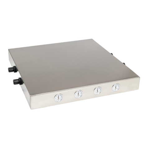
Terra Universal Pass-Through Installation guide

Installation and Operating Guide Document No. 1800-07
Cleanroom Pass-Through Chambers
© Copyright 2017 Terra Universal Inc. All rights reserved. • Revised Jul. 2020
Terra Universal, Inc. • TerraUniversal.com • 800 S. Raymond Ave. • Fullerton, CA 92831 • TEL: (714) 578-6000 • FAX: (714) 578-6020

Installation and Operating Guide
Cleanroom Pass-Through Chambers
© Copyright 2020 Terra Universal Inc. All rights reserved. • Revised Jul. 2020 • Document No. 1800-07
Terra Universal, Inc. • TerraUniversal.com • 800 S. Raymond Ave. • Fullerton, CA 92831 • TEL: (714) 578-6000 • FAX: (714) 578-6020 2
Table of Contents
Description....................................................................................................................................... 31.0
Installation........................................................................................................................................ 32.0
2.1 Wall Cut-Out......................................................................................................................................................................... 4
2.2 Installation for Standard Mounting Brackets................................................................................................................ 6
2.3 Installation for CleanMount® Brackets.......................................................................................................................... 7
2.4 Fire-Rated or Ruggedized Pass-Through Installation................................................................................................. 9
2.5 Floor-Mounted Pass-throughs.......................................................................................................................................10
2.6 Door Alignment .................................................................................................................................................................11
Protruding Exhaust Flange or Filter Housing...............................................................................113.0
Operation and Maintenance........................................................................................................... 124.0
4.1 Operation............................................................................................................................................................................ 12
4.2 Maintenance....................................................................................................................................................................... 12
4.3 Cleaning.............................................................................................................................................................................. 12
Warranty......................................................................................................................................... 135.0
Appendix: Installation Qualification Checklist ............................................................................. 146.0

Installation and Operating Guide
Cleanroom Pass-Through Chambers
© Copyright 2020 Terra Universal Inc. All rights reserved. • Revised Jul. 2020 • Document No. 1800-07
Terra Universal, Inc. • TerraUniversal.com • 800 S. Raymond Ave. • Fullerton, CA 92831 • TEL: (714) 578-6000 • FAX: (714) 578-6020 3
Proprietary Notice
Safety Notice
This manual pertains to proprietary devices manufactured by
Terra Universal, Inc. Neither this document nor any portion of
it may be reproduced in any way without prior written
permission from Terra Universal.
A thorough familiarity with all operating guidelines is essential to safe operation of
the product. Failure to observe safety precautions could result in poor
performance, damage to the system or other property, or serious bodily injury or
death. The following symbols are intended to call your attention to two levels of
hazard involved in operation.
Terra Universal makes no warranties applying to information
contained in this manual or its suitability for any implied or
inferred purpose. Terra Universal shall not be held liable for
any errors this manual contains or for any damages that
result from its use.
CAUTION
Cautions are used when failure to observe instructions could result in
significant damage to equipment.
WARNING
Warnings are used when failure to observe instructions or precautions
could result in injury or death.
The information presented here is subject to change without notice.
Description
1.0
Terra Universal Pass-Through Chambers allow room-to-room transfer of materials and samples without contamination. The
modular-panel mounting system allows installation on any wall type (such as wood or masonry) and thickness, and keeps
particle counts low by eliminating unnecessary room entry by personnel.
All cleanroom pass-throughs include a mechanical interlock system that minimizes the risk of cross-contamination. This device
allows only one open door at a time, thus m inimizing the amount of “dirty” air that can enter the cleanroom. General-use pass-
throughs utilize a chamber-mounted interlock (also called a single-wall design). An isolated interlock (or double-wall design)
simplifies cleaning and eliminates cracks that can harbor contaminants, making it ideal for the life sciences and clinical
applications.
CleanMount® System
The CleanMount® System (featured on select pass-throughs) utilizes a clamping mechanism to allow the pass-through to be
installed without any fasteners piercing the wall surface. This design enables quick installation with minimal impact on any
high-grade finished surfaces, and a significant reduction in debris and airborne particulates. When making the wall cut-out for
this type of pass-through, installers now have the option of finishing and sealing the cut-out with a cleanroom-grade surface.
That way, if the pass-through must be removed at a later date, the CleanMount® System will disassemble quickly and cleanly
while the cleanroom can remain in operation.
Installation
2.0
CAUTION
The installer is responsible for ensuring all of the following:
•All sides of the wall cut-out must be flat and level within a tolerance of 1/16” for every 36”.
•If the pass-through will be floor-mounted, the floor underneath and surrounding the pass-
through must also be flat and level within a tolerance of 1/16” for every 36”.
•If the pass-through includes optional components that have been preinstalled, such as an
exhaust flange or ULPA filter housing, these must be removed prior to installation (See Section
6.0 Optional Pass-Through Features).
Failure to comply with any of the instructions contained in this manual can result in damage to the unit
or improper installation, rendering the pass-through inoperable.
Installation and Operating Guide
Cleanroom Pass-Through Chambers
© Copyright 2020 Terra Universal Inc. All rights reserved. • Revised Jul. 2020 • Document No. 1800-07
Terra Universal, Inc. • TerraUniversal.com • 800 S. Raymond Ave. • Fullerton, CA 92831 • TEL: (714) 578-6000 • FAX: (714) 578-6020 4
2.1 Wall Cut-Out
1. Below chart compares the two bracket designs to help identify the mounting bracket style on your pass-through.
CleanMount® designs use lag bolts on either side of the chamber, thus requiring extra clearance in the wall cut-out
Figure 1: (from left) Pass-through with Standard Mounting bracket and Pass-through with CleanMount® Mounting Bracket

Installation and Operating Guide
Cleanroom Pass-Through Chambers
© Copyright 2020 Terra Universal Inc. All rights reserved. • Revised Jul. 2020 • Document No. 1800-07
Terra Universal, Inc. • TerraUniversal.com • 800 S. Raymond Ave. • Fullerton, CA 92831 • TEL: (714) 578-6000 • FAX: (714) 578-6020 5
2. Make a wall cut-out of the size specified in the table below.
Mounting Bracket Style
Wall Cut-Out Dimensions
Standard
Add 1/2" to the width and 1/2" to the height of the outside of the chamber
CleanMount®
Add 3” to the width and 1” to the height of the outside of the chamber
3. Add framing to the inside of the wall cut-out using a rigid support material, such as wood or metal.
4. Finish the wall cut-out with an appropriate substrate and finishing material. As a general rule, the wall cut-out should have
the same grade of finishing as the wall it is installed in (e.g. cleanroom-grade materials).
Figure 2: from left) Pass-through with Standard Mounting bracket and Pass-through with CleanMount® Mounting Bracket

Installation and Operating Guide
Cleanroom Pass-Through Chambers
© Copyright 2020 Terra Universal Inc. All rights reserved. • Revised Jul. 2020 • Document No. 1800-07
Terra Universal, Inc. • TerraUniversal.com • 800 S. Raymond Ave. • Fullerton, CA 92831 • TEL: (714) 578-6000 • FAX: (714) 578-6020 6
2.2 Installation for Standard Mounting Brackets
1. Terra Universal does not supply fastener hardware for the mounting
brackets. Choose fasteners that are appropriate for mounting to your wall
material (drywall or masonry, for example).
2. Prepare the wall cut-out as outlined in Section 2.1.
3. Loosen the pass-through from the shipping pallet by removing the small
brackets attached on either side. See Section 3.0 if your pass-through
chamber includes an exhaust flange or filter housing for ventilation.
4. Slide the loose mounting bracket off of the body of the pass-through and
set it aside. The other mounting bracket assembly is welded to the pass-
through either 2” from one end (standard mounting) or near the middle
(center mounting), depending on the wall thickness specified in the
original order.
5. Insert the pass-through into the wall until the fixed (welded) mounting
bracket is flush against the wall. Use a level to straighten the chamber
and fasten the bracket to the wall through the pre-drilled holes. The
number of fasteners needed depends on the size of the chamber.
6. From the “dirty” side, slide the loose mounting bracket onto the chamber
and secure it to the wall with fasteners. Do not over-tighten the fasteners as
this may bend the bracket and create gaps. Use silicone caulk or expansion
foam to fill gaps as needed.
7. If the chamber protrudes from the wall by 24" or more, install the included
support bracket(s) to the wall, below the chamber (See Figure 3 bottom
right). The body of the pass-through chamber rests upon the bracket and
no fasteners required.
8. Check alignment of the pass-through chamber doors by following the
procedures outlined in Section 2.6 Door Alignment.
Figure 4: Pass-through with standard mounting
brackets, fastened to the wall
Figure 3: Diagram of installed pass-through with standard
mounting brackets

Installation and Operating Guide
Cleanroom Pass-Through Chambers
© Copyright 2020 Terra Universal Inc. All rights reserved. • Revised Jul. 2020 • Document No. 1800-07
Terra Universal, Inc. • TerraUniversal.com • 800 S. Raymond Ave. • Fullerton, CA 92831 • TEL: (714) 578-6000 • FAX: (714) 578-6020 7
2.3 Installation for CleanMount® Brackets
Installation Video: To view a video demonstrating a similar
installation, please visit the following link:https://youtu.be/1tnedlfBi9w
1. Prepare the wall cut-out as outlined in Section 2.1.
2. See Section 3.0 if your pass-through chamber includes an
exhaust flange or filter housing for ventilation.
3. Standing on the “clean” side of the wall, slide the pass-through
completely into the wall until the attached mounting bracket is
flush with the “clean”-side wall surface (See Figure 5).
4. Optional support brackets are recommended if the chamber
protrudes from the wall by 24" (See Figure 5) or more.
5. Check alignment of the pass-through chamber doors by
following the procedures outlined in Section 2.6 Door
Alignment.
6. The “dirty”-side mounting bracket is shipped preassembled. Pop
off the bracket covers and slide the bracket onto the body of the
pass-through (See Figure 6). If necessary, detach one section of
the mounting bracket by removing the two screws at each corner,
creating a “C” shape. Slide the “C”-shaped bracket onto the
chamber and then reattach the missing section, tightening all
corner screws once the bracket is in place.
7. Confirm chamber positioning with a level, and insert the provided
lag bolts into the pre-drilled holes in the mounting bracket. Thread
the lag bolt into the guide that extends from the “clean”-side
mounting bracket (See Figure 7). The size of the pass-through will
determine the number of bolts required. Use a socket wrench to
tighten the lag bolts into the pre-welded nuts until the mounting
bracket is flush against the wall (See Figure 8). Be careful not to
over-tighten the “dirty”-side mounting bracket lag bolts. The bracket
should be secured against the wall but should not bend inward
(forming gaps).
8. Install the bracket covers by snapping each of them into the
bracket clips (See Figure 8)
Figure 6: Slide the “dirty”-side mounting bracket onto
the body of the pass-through
Figure 5: Diagram of installed CleanMount® Pass-through

Installation and Operating Guide
Cleanroom Pass-Through Chambers
© Copyright 2020 Terra Universal Inc. All rights reserved. • Revised Jul. 2020 • Document No. 1800-07
Terra Universal, Inc. • TerraUniversal.com • 800 S. Raymond Ave. • Fullerton, CA 92831 • TEL: (714) 578-6000 • FAX: (714) 578-6020 8
NOTE
Terra Universal
provides lag bolts that accommodate wall thicknesses between 4” and 6”. Longer lag-
bolts are required for thicker walls (not provided by Terra).
NOTE
Although the mounting brackets are designed to provide a sufficient seal against the wall surface,
silicone
caulking may be used to fill any seams or gaps after the installation is complete.
Figure 7: Thread the lag bolt into the guide attached
to the “clean”-side bracket, sandwiching the wall
between the brackets
Figure 8: Snap the bracket covers back into place to
hide the lag bolts and other hardware

Installation and Operating Guide
Cleanroom Pass-Through Chambers
© Copyright 2020 Terra Universal Inc. All rights reserved. • Revised Jul. 2020 • Document No. 1800-07
Terra Universal, Inc. • TerraUniversal.com • 800 S. Raymond Ave. • Fullerton, CA 92831 • TEL: (714) 578-6000 • FAX: (714) 578-6020 9
2.4 Fire-Rated or Ruggedized Pass-Through Installation
CAUTION
To ensure proper functioning of the self-closing door, the installer is responsible for the following:
•All sides of the wall cut-out must be flat and level.
•The fire-rated door must be tested before and after any fastening steps, including installing the mounting
bracket and installing the support bracket (if a support bracket is used).
•Before fastening, the pass-through is checked with a level and shimmed where necessary.
Failure to comply with any of the instructions contained in this manual can result in improper installation or
damage to the unit, rendering the pass-through inoperable.
Required Materials:
Appropriate fasteners for wall type
Level
Shims
Fire-rated caulking or expansion foam
1. Prepare the wall cut-out as outlined in Section 2.1.
2. See Section 3.0 if your pass-through chamber includes an exhaust flange or
filter housing for ventilation.
3. Insert the pass-through into the wall until the attached bracket (flange)
contacts the wall surface.
4. Ensure the bracket is flush against the wall and use a level to check the
chamber positioning. If necessary, use shims to properly align the chamber
in the wall cut-out.
5. Open the fire-rated door and locate the predrilled holes along the interior
edge. Insert a fastener into the wall at each corner to temporarily tack the
pass-through chamber in position.
6. Test the fire-rated door to ensure that it closes properly. Adjust the alignment of the pass-through as needed before
proceeding with the installation.
7. After confirming proper functioning of the pass-through doors, install the remaining fasteners.
8. For large pass-throughs requiring a support bracket, install the support bracket now (See Figure 1 right). Support
brackets should be positioned to press up against the bottom of the chamber and fastened to the wall only. The pass-
through chamber should rest its weight on the bracket, without any fasteners piercing the body of the pass-through.
9. On the opposite side of the wall (the “dirty-side” where the pass-through body extends from the wall), slide the loose
mounting bracket onto the body of the pass-through.
10. Fasten the bracket to the wall surface only. Do not over-tighten the fasteners as this may bend the bracket and create
gaps.
11. Test the pass-through doors again for proper functioning.
Figure 9: Open the chamber door to access
the holes for fasteners

Installation and Operating Guide
Cleanroom Pass-Through Chambers
© Copyright 2020 Terra Universal Inc. All rights reserved. • Revised Jul. 2020 • Document No. 1800-07
Terra Universal, Inc. • TerraUniversal.com • 800 S. Raymond Ave. • Fullerton, CA 92831 • TEL: (714) 578-6000 • FAX: (714) 578-6020 10
12. After installation is complete, fire-rated caulking or expansion foam may be used to fill any remaining gaps, if needed.
2.5 Floor-Mounted Pass-throughs
CAUTION
T
he floor underneath and surrounding the pass-through must be flat and level within a tolerance of 1/16”
for every 36”.
An uneven floor surface
may cause gaps to appear between the pass-through components and the floor.
1. Prepare the wall cut-out outlined in Section 2.1
2. For pass-throughs with standard mounting brackets, complete the installation instructions outlined in Section 2.2. For
pass-throughs with CleanMount® brackets (flush-mount), complete the installation instructions outlined in Section 2.4.
3. Align the floor ramps with the bottom of the pass-through so that the two notches on the rear of the ramp hook onto the
studs below the pass-through doors. Push the ramp in until it is flush with the surface of the pass-through and then set it
down. The pass-through door may need to be opened to ensure the ramp is fitted properly. No fasteners are required.
NOTE
Although the
pass-through is designed to operate under positive pressure and assumes some leakage,
silicone
caulking may be used to fill any seams or gaps after the installation is complete.
Figure 10:Hook the ramps on the studs at the bottom of the pass-through

Installation and Operating Guide
Cleanroom Pass-Through Chambers
© Copyright 2020 Terra Universal Inc. All rights reserved. • Revised Jul. 2020 • Document No. 1800-07
Terra Universal, Inc. • TerraUniversal.com • 800 S. Raymond Ave. • Fullerton, CA 92831 • TEL: (714) 578-6000 • FAX: (714) 578-6020 11
2.6 Door Alignment
Pass-through chambers being installed in a cleanroom wall must
be properly aligned to ensure proper operation of the latch and the
interlock mechanism.
1. Align the pass-through chamber so that the front door latches
are centered in the corresponding catch (see Figure 11). To
align the chamber, one corner may need to be shimmed
before bolting the mounting brackets to the wall.
2. Large chambers may include support frames with leveling
feet. The feet adjacent to the cleanroom wall should be
adjusted to support the chamber once the “clean” side door
has been properly aligned.
3. Repeat this procedure for the opposite (i.e., “dirty”) door.
Raise or lower the chamber corners until the door latch engages
the center of the catch. Then adjust the support frame leveling
feet to retain this alignment. If your installation includes support brackets, mount these to the chamber and the wall to
achieve correct door alignment (See Figure 3in Section 2.2above).
Protruding Exhaust Flange or Filter Housing3.0
If the pass-through arrived with either an exhaust flange or an ULPA filter housing preinstalled, these features will need to be
detached from the pass-through prior to installation to allow the pass-through to fit through the wall cut-out.
Figure 12: Exhaust Flange
Figure 13: ULPA Filter Housing
1. To remove the exhaust flange, unscrew the 8 domed cap nuts around the base of the flange and remove the flange (See
Figure 12).
2. To remove the ULPA filter housing, unscrew the 4 domed cap nuts on either side of the housing and remove both the
ULPA filter and the housing (See Figure 13).
3. Reinstall these features once the pass-through installation has been completed. Installation is the reverse of disassembly.
Figure 11:Properly aligned LiftLatch

Installation and Operating Guide
Cleanroom Pass-Through Chambers
© Copyright 2020 Terra Universal Inc. All rights reserved. • Revised Jul. 2020 • Document No. 1800-07
Terra Universal, Inc. • TerraUniversal.com • 800 S. Raymond Ave. • Fullerton, CA 92831 • TEL: (714) 578-6000 • FAX: (714) 578-6020 12
Operation and Maintenance4.0
4.1 Operation
The operator should always verify that the opposite door is fully shut prior to opening a door. Do not
yank, shake, or apply excessive force to the doors.
Attempting to force open a door while the
mechanical interlock is engaged may result in damage to th
e unit.
CAUTION
The FirmLok™ mechanical interlock system will prevent both doors from being opened at the same time.This system cannot
be disabled, so it is important that operators fully close and latch the pass-through door after use.
4.2 Maintenance
•
Do not clean acrylic with alcohol or other strong cleaning agents.
•
Do not expose static-dissipative PVC to extreme heat or direct sunlight.
CAUTION
The FirmLok™ mechanical interlock system is maintenance-free and rated for over 100,000 operations. If the interlock system
malfunctions, please contact Terra Universal.
4.3 Cleaning
Acrylic and Static-Dissipative PVC Windows
Acrylic and static-dissipative PVC should be periodically cleaned with clean, lukewarm water and a clean nonabrasive cloth. If
desired, a mild, non-abrasive detergent may also be used. Use only light pressure when cleaning. If the outside of the acrylic is
exceptionally dirty or gritty, rinse the surface first by lightly swabbing a saturated cloth over the surface and allowing surfactants
to drain away. Avoid rubbing dirt or grit into the surface. Turn the cloth often and replace with a clean cloth frequently. Dry the
acrylic by blotting gently with a clean, dry cloth.
Stainless Steel
Clean stainless steel surfaces with alcohol (or similar cleaning agent) and a damp cloth.
Terra recommends use of knitted polyester wipers or spun-lace, non-woven blends of cellulose and polyester manufactured
and packaged specifically for cleanroom use. These products are manufactured under tightly controlled conditions that restrict
the use of binders or chemical treatments that can outgas, and cleanroom packaging and strict lot control ensure optimal
cleanliness.
Less critical environments (ISO 6 – 8 / Class 1000 – 100,000) generally tolerate more absorbent materials made of 100%
cotton twill or cellulose.
Clean surfaces with clean, lukewarm water with or without a mild, non-abrasive detergent. In critical cleanroom applications, DI
water or isopropyl alcohol may be required.
For thorough, repeatable results, avoid cleaning with a circular motion, which rubs dirt or grit into the surface. Using mild
pressure, wipe in one direction, from top to bottom or side to side, in slightly overlapping stokes. Fold the wiper between
strokes, and replace with a clean wiper often.

Installation and Operating Guide
Cleanroom Pass-Through Chambers
© Copyright 2020 Terra Universal Inc. All rights reserved. • Revised Jul. 2020 • Document No. 1800-07
Terra Universal, Inc. • TerraUniversal.com • 800 S. Raymond Ave. • Fullerton, CA 92831 • TEL: (714) 578-6000 • FAX: (714) 578-6020 13
Warranty5.0
Products Manufactured by Terra: Terra Universal, Inc., warrants products that it manufactures to be free from defects for a
period of 12 months for parts and 90 days for labor, commencing from the date of shipment. Terra’s sole responsibility is to
repair or replace, at its option, any part of the product that proves defective or malfunctioning during this time limit. In some
cases, components incorporated in Terra Universal products are covered by additional warranties from component
manufacturers; obtain specific information from Terra sales representatives. This warranty is void if the equipment is abused or
modified by the customer, is operated outside Terra’s operating instructions or specifications, or is used in any application other
than that for which it is specified. This warranty does not include routine maintenance or service procedures, breakage of quartz
baths after 60 days, shipping damage, nor damage from misuse, intentional or unintentional abuse, neglect, natural disasters,
or acts of God.
Products Manufactured by Others: Terra Universal, Inc., warrants that, to the best of its ability, Terra’s representations of
products that are manufactured by others reflect the manufacturer’s representations, subject to change without notice. Sole
warranty for these products is the original manufacturer’s warranty that is passed forward to the purchaser and constitutes the
customer’s sole remedy for these products. Detailed warranties for distributed products are available through Terra sales
representatives.
Freight Shortage or Damage: Upon receipt of any equipment from Terra Universal, Inc., customer shall immediately unpack
and inspect for damage or shortage. The customer shall not accept a damaged package or a short shipment until the carrier
makes a "damage or shortage" notation on both the carrier's and customer's copy of the freight bill or delivery receipt. Service
title passes when the shipment is loaded, so customer is responsible for filing and collecting a freight claim. Any replacement
products must be ordered and paid for separately. For Terra's "Policy and Procedures for Returning Goods," see Terra's
Internet site: www.TerraUniversal.com.
Generally, customers can improve the chance of collecting on a freight claim by following these procedures: 1) formally
requesting that the carrier inspect the shipment immediately upon suspecting damage or shortage to verify condition; 2)
notifying the carrier upon discovery of concealed damage and requesting an inspection within 15 days of receipt, both in person
or phone and following up via mail; 3) keeping the shipment as intact as possible, including retaining original packaging
materials and keeping the product as close to the original receiving location as possible; 4) holding salvage for disposition by
the carrier.
All Claims: Terra Universal expressly disclaims all other warranties, expressed or implied or implied by statute, including the
warranties of merchantability or fitness for intended use. Terra Universal is not responsible for consequential or incidental
damages arising out of the purchase or use of the products supplied by Terra Universal. Terra Universal is not liable for
damage to facilities, other equipment, products, property or personnel of others, or of their agents, suppliers, or affiliated
parties, which is caused or alleged to have been caused by products supplied by Terra Universal. In any event or series of
events, Terra Universal’s total liability for any and all damages whatsoever is limited to the lesser of the actual damages or the
original invoice cost of the items alleged to have caused the damage. The customer’s sole and exclusive remedy for any cause
of action whatsoever is repair or replacement of the non-conforming products or refund of the actual purchase price, at the sole
option of Terra Universal. All claims must be made in writing within 90 days of the date the product was shipped. Any claims not
made within this time limit shall be deemed waived by the customer. Terra Universal is not responsible for any additional costs
of repair caused by poor packaging or in-shipment damage during return.
Warranty Returns: All warranty returns must be authorized in advance by Terra Universal and approved under an RMA.
Unless approved in advance for good reason, all returns must be in original condition, including all manuals, and must be
packaged in original packaging materials. All returned goods are to be shipped to Terra Universal, freight prepaid at customer’s
expense. See Terra’s “Policy and Procedure for Returned Goods.”
Thank you for ordering from
Terra Universal!

Installation and Operating Guide
Cleanroom Pass-Through Chambers
© Copyright 2020 Terra Universal Inc. All rights reserved. • Revised Jul. 2020 • Document No. 1800-07
Terra Universal, Inc. • TerraUniversal.com • 800 S. Raymond Ave. • Fullerton, CA 92831 • TEL: (714) 578-6000 • FAX: (714) 578-6020 14
Appendix: Installation Qualification Checklist6.0
To confirm proper installation, fill out the checklist below for each pass-through installed. Note any suspected damage, deviations
from installation procedures, or performance issues in the Comments section. Equipment is found to be acceptable only when all
installation criteria have been accepted and the document signed by the relevant parties.
Installation Checklist
Verify the following:
Check if
Confirmed and
Accepted
Performed by / Date
All mounting brackets are secured tightly
against the wall
Support brackets (if provided) have been
installed below the pass-through
No gaps larger than 1/16” exist between
the pass-through and the wall/floor surface
Pass-through doors open smoothly and
close completely, with the latch centered in
the corresponding catch
The seal/gasket on the inside of each door
is intact, fully adhered to the door, and
seats tightly against the face of the pass-
through without visible gaps
The interlock functions properly,
preventing the door from opening when
the opposite door is also open
The interior of the pass-through is clean
and clear of any debris from installation
Floor ramps (if provided) have been
positioned at the base of the pass-through
Performed by: _________________________________ Date: _________________
Reviewed by: _________________________________ Date: _________________
Comments:
Table of contents
Other Terra Universal Laboratory Equipment manuals

Terra Universal
Terra Universal Cleanroom Airlock Installation guide

Terra Universal
Terra Universal Ductless Exhaust Fume Hood Installation guide

Terra Universal
Terra Universal 1580-03 User manual

Terra Universal
Terra Universal Smart ECM User manual

Terra Universal
Terra Universal Smart Pass-Through Installation guide

Terra Universal
Terra Universal USP 797 User manual

Terra Universal
Terra Universal ValuLine Softwall Installation guide

Terra Universal
Terra Universal Smart Desiccator Installation guide

Terra Universal
Terra Universal 310 Series User manual