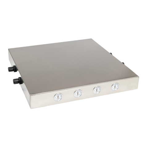
Terra Universal USP 797 User manual

Quick-Start Operating Guide Document No. 1800-90
USP 797 Modular Cleanroom
© Copyright 2015 Terra Universal Inc. All rights reserved. Rev. December. 2019
Terra Universal, Inc. • TerraUniversal.com • 800 S. Raymond Ave. • Fullerton, CA 92831 • TEL: (714) 578-6000 • FAX: (714) 578-6020

Quick-Start Operating Guide
USP 797 Modular Cleanroom
© Copyright 2015 Terra Universal Inc. All rights reserved. • Revised Dec 2019• Document No. 1800-90
Terra Universal, Inc. • TerraUniversal.com • 800 S. Raymond Ave. • Fullerton, CA 92831 • TEL: (714) 578-6000 • FAX: (714) 578-6020 2
Table of Contents
Notices: Proprietary & Safety.................................................................................................................. 3
Section 1.0 – Description
Fan Filter Units........................................................................................................................................ 4
Fluorescent Illuminator Module............................................................................................................... 5
Side Walls............................................................................................................................................... 5
Entrances................................................................................................................................................ 6
Control Panel .......................................................................................................................................... 6
Duplex Power Outlet ............................................................................................................................... 7
Stainless Steel Window........................................................................................................................... 7
Operation Status Indicator ...................................................................................................................... 7
Section 2.0 –Installation
Site Preparation ...................................................................................................................................... 8
Required Installation Equipment ............................................................................................................. 8
Component List....................................................................................................................................... 9
Component Description......................................................................................................................... 11
Frame Components .............................................................................................................................. 14
Assembly Drawings .............................................................................................................................. 16
Installing the Support Frame and Control Panel ................................................................................... 17
Installing the Power Distribution Module ............................................................................................... 19
Installing Ceiling Components............................................................................................................... 21
Fan Filter Unit Hardwiring ..................................................................................................................... 24
Installing Wallboard and Air Vents ........................................................................................................ 25
Installing Viewing Window..................................................................................................................... 26
Applying FRP Interior Surfaces............................................................................................................. 27
Door Installation.................................................................................................................................... 30
Installing Top Corners and Side Trim.................................................................................................... 31
Section 3.0 – Operation & Maintenance
Recommended Operation Guidelines ................................................................................................... 33
Maintenance ......................................................................................................................................... 34
FFU Adjustment and Filter Replacement .............................................................................................. 34
Cleaning................................................................................................................................................ 37
Section 4.0 – Warranty ................................................................................................................. 38
Section 5.0 – Spare Parts and Accessories.......................................................................... 39
Appendix: USP 797 Compliance Testing Protocol............................................................. 41

Quick-Start Operating Guide
USP 797 Modular Cleanroom
© Copyright 2015 Terra Universal Inc. All rights reserved. • Revised Dec 2019• Document No. 1800-90
Terra Universal, Inc. • TerraUniversal.com • 800 S. Raymond Ave. • Fullerton, CA 92831 • TEL: (714) 578-6000 • FAX: (714) 578-6020 3
USP 797 Compliant Cleanrooms
Installation and operating instructions in this manual pertain to Terra Modular Cleanrooms designed to comply with the provisions of
USP 797 for sterile compounding. It is recommended that you review this manual in its entirety prior to installation.
These cleanrooms feature Terra’s standard hardwall construction configured in two standard sizes: 6’ x 8’ and 6’ x 10’. Refer to
attached system drawings for details on any custom features specified in your order, including custom dimensions. Standard
designs include a “buffer” area (main processing room) and anteroom (staging/gowning area). These spaces are divided by a swing
door mounted to an internal wall, which maintains the required pressure differential between the two areas.
Modular Hardwall Cleanrooms designed to the requirements of USP 797 feature three Fan Filter Units, which are factory set at
medium speed. At this setting, these systems meet the requirements for internal pressure, air displacement, and cleanliness
specified by USP 797 for both the ISO 7 “buffer room” (main processing room) and ISO 8 ante room (see “Compliance Testing
Protocol” for more information).
Users are typically required to undergo on-site testing and certification by an independent testing company authorized by
the relevant regulating agency. Any data furnished by Terra, including information published in Terra literature or web
pages, do not constitute formal certification to USP 797 or any other specification or regulation.
1.0 Description
Terra Universal’s Modular Cleanroom provides an
economical alternative to high-cost, fixed-installation
cleanrooms while providing the rigidity and durability of a
freestanding room.
Designed to combine economy and versatility, this system
features ceiling HEPA Fan Filter Units (FFUs) that direct a
continuous flow of HEPA or ULPA-filtered air through the
enclosure. The continuous positive pressure created by this
laminar airflow helps to control particles generated inside
the enclosure by sweeping them downward through the
room and out the air vents. This design also helps to
prevent contaminants from entering the cleanroom when
an access door is opened.
Proprietary Notice
This manual pertains to proprietary devices manufactured by Terra
Universal, Inc. Neither this document nor any portion of it may be
reproduced in any way without prior written permission from Terra
Universal.
Terra Universal makes no warranties applying to information contained
in this manual or its suitability for any implied or inferred purpose.
Terra Universal shall not be held liable for any errors this manual
contains or for any damages that result from its use. The information
presented here is subject to change without notice.
Safety Notice
A thorough familiarity with all operating guidelines is essential to safe
operation of the product. Failure to observe safety precautions could
result in poor performance, damage to the system or other property, or
serious bodily injury or death.
The following symbols are intended to call your attention to two levels
of hazard involved in operation:
Cautions are used when failure to observe instructions
could result in significant damage to equipment.
CAUTION
Warnings are used when failure to observe instructions
or precautions could result in injury or death.
WARNING
ISO 7 Buffer Room of Terra Universal’s USP 797 Cleanroom. Depending
on specified dimensions, your cleanroom may be configured differently.
Glovebox, hood and other furnishings not included.

Quick-Start Operating Guide
USP 797 Modular Cleanroom
© Copyright 2015 Terra Universal Inc. All rights reserved. • Revised Dec 2019• Document No. 1800-90
Terra Universal, Inc. • TerraUniversal.com • 800 S. Raymond Ave. • Fullerton, CA 92831 • TEL: (714) 578-6000 • FAX: (714) 578-6020 4
The Modular Hardwall Cleanroom is supported by a rigid frame structure consisting of powder-coated 2”- square steel
upright members and horizontal cross members. Support braces along the horizontal cross members form 2-foot x 4-
foot ceiling grids that accommodate FFUs, lights and ceiling panels.
Cleanroom walls consist of 5/8”-thick fire-resistant wallboard attached to the support frame, with fiberglass-reinforced
plastic (FRP) panels laminated to the inside wallboard to create a smooth, clean, sealed surface that can be easily
washed and sterilized. Terra does not provide a finish for the exterior wallboard. When installation is
completed, however, this surface can be finished and painted relatively easily and inexpensively to match
your facility.
Fan Filter Units (FFUs)
Fan Filter Units (FFUs) direct a vertical laminar flow of filtered air downward through the enclosed cleanroom area.
Each includes a 3-speed impeller blower (average flow: 650 CFM, operating at medium speed under filter load)
mounted in a powder-coated steel housing with a plenum design that optimizes uniform air velocity across the entire
face of the filter. A HEPA (high efficiency particulate air) filter installed inside the
housing is rated 99.99% efficient at 0.3 um particles. The filtration medium
consists of micro porous polyurethane minipleats held in place by strong, rigid
plastic separators that keep the medium from nesting. This design channels
airflow with optimal efficiency to reduce resistance. The filter is sealed into the
sturdy steel frame with a fire-retardant, non-outgassing adhesive. On an optional
basis, an ULPA (ultra-low penetration air) filter, rated 99.999% efficient at 0.12
um particles, may be substituted for the HEPA filter. Power to the Fan Filter
Units is controlled by a master ON/OFF switch located on the cleanroom control
panel.
All 120VAC units and 220VAC, 60Hz units are UL listed. CE-marked models are available for 220VAC, 50Hz
operations. FFU quantity in USP 797 Cleanroom: three (3).
IMPORTANT SAFETY NOTICE
Terra Universal cleanrooms are not designed to support more weight than the blower modules and lighting fixtures
originally installed. Ceiling grid beams are not load-bearing and will not support personnel or other additional loads.
Placing added weight on the ceiling grid may result in serious damage to the cleanroom and its occupants.
Yellow safety notice supplied by Terra Universal must be affixed prominently to the cleanroom grid.

Quick-Start Operating Guide
USP 797 Modular Cleanroom
© Copyright 2015 Terra Universal Inc. All rights reserved. • Revised Dec 2019• Document No. 1800-90
Terra Universal, Inc. • TerraUniversal.com • 800 S. Raymond Ave. • Fullerton, CA 92831 • TEL: (714) 578-6000 • FAX: (714) 578-6020 5
Recommended Fan Filter Configurations (based on ceiling height of 8 feet or less)
Recommended Fan Filter Configurations
Nominal
Dimensions
No. of
Ceiling
Bays
No. of Filter Modules to meet ISO Cleanliness
Standards
ISO 3
ISO 4
ISO 5
ISO 6
ISO 7
ISO 8
8' x 8'
8
5 -8
4 - 8
3 - 6
2 - 3
1 - 2
1
8' x 12'
12
7 - 12
6 - 12
4 - 8
3 - 5
2 - 3
1 - 2
8' x 16'
16
10 - 16
8 - 16
6 - 11
4 - 6
2 - 4
1 - 3
12' x 12'
18
11 - 18
9 - 18
6 - 13
5 - 7
3 - 5
1 - 3
12' x 16'
24
14 - 24
12 - 24
8 - 17
6 - 10
4 - 6
2 - 4
Fluorescent Illuminator Module
Each fluorescent light fixture is externally mounted to ensure effective illumination of the
work area without interfering with the controlled air stream. Each module contains four
40W fluorescent T8 light tubes controlled by a master switch mounted on the main
Cleanroom Control Panel. The housing is made of epoxy-finished aluminum.
Power Requirements: 115VAC/60Hz, 1.50A Each (US)
277VAC/50Hz, 0.65A Each (International)
Quantity: Two, one in Buffer room, one in Antechamber
Blank Ceiling Panels
All remaining ceiling grids are covered with blank panels, which can be removed to allow installation of additional fan
filter units or illuminator modules. Panels are made of white polypropylene. All of these ceiling modules rest against
the ceiling grid frame to form a tight seal along the ceiling grid perimeters.
Walls
IMPORTANT SAFETY NOTICE
All personnel should wear eye protection and respirators in addition to gloves and appropriate
clothing while cutting, drilling or sanding FRP panels in accordance with local state safety laws.
Structural support is provided by powder-coated steel framing, consisting of 1.75” square steel upright and horizontal
members. Steel frames ensure a rigid, free-standing support structure that requires no external bracing. Walls are
finished with Fiberglass-Reinforced Plastic (FRP) panels applied to fire-resistant wallboard. FRP panels are available
in a Class A FM-approved material and a Class C material.
Both Classes of FRP panels are applied with a unique advanced polymer non-outgassing adhesive, allowing
installation on porous and nonporous surfaces. A specialized seam sealant provides trim-free seams that expand and
contract to accommodate temperature-induced dimensional changes without creating cracks or gaps. Finally, a
patented surfacing technology seals panels uniformly to enhance durability and prevent particle emission and
microbial growth. The result: smooth, chemical-resistant, sealed, cleanroom-compatible walls that won’t shed
particles or outgas.
Class A BioSafe interior panels are the only FRP wall panels certified to ISO 5 standards for added cleanliness, and
Factory Mutual (FM) approved for increased safety and fire hazard protection.

Quick-Start Operating Guide
USP 797 Modular Cleanroom
© Copyright 2015 Terra Universal Inc. All rights reserved. • Revised Dec 2019• Document No. 1800-90
Terra Universal, Inc. • TerraUniversal.com • 800 S. Raymond Ave. • Fullerton, CA 92831 • TEL: (714) 578-6000 • FAX: (714) 578-6020 6
BioSafe® FRP Wall Panel Specifications
Composition: Random chopped fiberglass in a modified polyester copolymer resin mix, with smooth finish and
proprietary surface seal
Thickness: 0.075” (1.9 mm)
Total VOC: 22.16 ppb (Methyl methacrylate): 1.66 ppb (ISO 16000-9) - FDA and USDA approved
Color: White
BioSafe FRP Wall Panel Certifications*
•Particle emission ISO Class 5 – 8 per ISO 14644-1
•Meets USDA/FSIS (US Dept of Agriculture/Food Safety Inspection Service) requirements
•Does not support mold or mildew (per ASTM D3273 and ASTM D3274)
•Meets minimum requirements of major model building codes for Class A interior wall and ceiling finishes of
flame spread ≤ 25, smoke developed 450 or less (per ASTM E-84)
•Meets requirements of ASTM D5319 for Classification Class A / Grade 5 (refers to standard specifications
for materials, workmanship and physical requirements)
•FM Approved under FM Research Approved FRP, Class 1 Interior Finish Material in accordance with FM
Research with Canada and the United States Approval Standard 4880
•Biological Resistance rating of 0 – Excellence per ISO 846
* ISO 5 and FM ratings apply to Class A FRP panels.
Entrances
1. Access Door: An access door, made of rigid static-dissipative PVC or polycarbonate mounted in an aluminum
frame, affords entrance to the enclosure. The door is 36”W x 80”H and includes inside and outside handles and
a pneumatic self-closing damper. The door opens inward, allowing hands-free entry as required by cleanliness
protocol.
Note: This room is not sealed airtight. Because it is designed to operate under positive
pressure, small gaps around the doors or in the panel structure will not compromise
clean conditions.
2. Antechamber/Gowning Area: The USP 797 modular cleanroom includes an
antechamber, which can function as a gowning or staging area. It includes one Fan Filter
Unit to meet ISO 8 cleanliness classification. It is separated from the main “buffer” area
by a second swing door, as described above.
Control Panel
The Control Panel, mounted to the right of the access door, includes a power switch for the
fluorescent light and ON/OFF pushbuttons to control operation of the FFUs. When FFUs are
in operation, the Operation Status Indicator lights (blue TUI logos at each corner of the top
exterior trim) glow to indicate that the room is operational. When the FFU power switch is off,
the Operation Status Indicator lights flash intermittently to call attention to the inoperability of
the room.
The Control Panel also includes two Magnehelic®differential pressure gauges that
monitor air pressure. These gauges measure differential between the buffer room
and antechamber, as well as antechamber and outside room (general lab or
pharmacy area): scale range is - 0.25 to + 0.25” WC.
Control Panel showing ON/OFF
switch for Fan Filter Units, light
switch, and Magnehelic pressure
gauges for antechamber (top) and
buffer area (bottom). A lock-out
cage can be installed to prevent
tampering with fan operation.

Quick-Start Operating Guide
USP 797 Modular Cleanroom
© Copyright 2015 Terra Universal Inc. All rights reserved. • Revised Dec 2019• Document No. 1800-90
Terra Universal, Inc. • TerraUniversal.com • 800 S. Raymond Ave. • Fullerton, CA 92831 • TEL: (714) 578-6000 • FAX: (714) 578-6020 7
The Control Panel is factory installed/wired, prior to shipping.
Duplex Power Outlet
The USP 797 Cleanroom includes a 120VAC, 60Hz duplex power outlet mounted along the rear wall of the Buffer
Room, providing a convenient power source for equipment installed inside the cleanroom (220VAC, 60Hz duplex
outlet also available).
The outlet is factory-installed prior to shipping.
Stainless Steel Window
The USP 797 includes a 0.25”-thick, 44.5”W x 34”H tempered glass
viewing window installed in a stainless steel frame on the buffer room
wall.
Operation Status Indicator
Mounted to the top trim strip above each corner, these LED indicators
glow to show that Fan Filter Units (FFUs) are turned on, and flash if they
are turned off. They thus provide a convenient visual indication of proper
room operation.
2.0 Installation
Component Inspection: Unpack all system components and check for damaged or missing parts (refer to component
list/chart on the next page as well as the sales order to determine correct quantity of parts). Any damage should be
reported to the shipping company immediately. Contact Terra Universal if any parts are missing.
Site Preparation
Refer to Terra installation contract for details of work to be performed by Terra Universal technicians.
A. Site preparation requirements should be observed for any installation performed by Terra Universal technicians.
B. Customer facility area where the cleanroom is to be installed must provide a minimum clearance of 18” (including
fixtures, ducts and pipes) on all sides and at least 24” of vertical clearance between the FFU inlet and ceiling.
Refer to drawing for Fan Filter Unit system inlet height.

Quick-Start Operating Guide
USP 797 Modular Cleanroom
© Copyright 2015 Terra Universal Inc. All rights reserved. • Revised Dec 2019• Document No. 1800-90
Terra Universal, Inc. • TerraUniversal.com • 800 S. Raymond Ave. • Fullerton, CA 92831 • TEL: (714) 578-6000 • FAX: (714) 578-6020 8
C. Customers must provide permanent electrical connection from facility supply panel to Terra Cleanroom Power
Distribution Modules (typically, one power line with 40A circuit breaker for a USP 797 room) in conformance with
local electrical code, as well as any vacuum, air, H20, sprinkler, or nitrogen connections required for the
cleanroom.
D. Customers must give advance notice of dates and times for Terra personnel to perform the installation. Short
notice may result in higher fees for travel and accommodations.
E. Customers are to provide utilities, installation power, and removal of any packing material.
F. Because installation requires unpacking and assembling components, customers are to ensure an adequate
staging area for parts and equipment adjacent to the assembly area, clear and ready for work.
G. Customers are to inform Terra Universal in advance of any requirements for security, escorts, special training,
badges, work hours, parking areas or special identification and how to obtain all such required permissions and
related items.
H. Prior to shipping, all frame and ceiling members are labeled at each end. Refer to the “Installation” section and
Appendix for detailed information on how your cleanroom is numbered.
I. Before you start assembly, it is mandatory that the floor is level to assure the completed room will fit properly and
be rectangular. Failure to level the floor may result in the inability to complete the assembly of the room or the
insertion of the blowers, lights or ceiling. For vertical alignment, measure with the leveler before assembly.
Required Installation Equipment (not included)
A. Handling cleanroom shipping crates, which generally measure over 300 inches long and weigh well over 1,000
pounds, requires at least one forklift or pallet jack. If crates must be moved through narrow aisles or entrances,
two forklifts or pallet jacks are recommended, one to support each end.
B. Unloading crates from the truck is much easier if you have a truck-high loading dock. Without such a dock, you
will need at least one forklift and a support to brace one end while the forklift is positioned beneath the center of
each crate. Several people are required to unload individual components from the crates.
C. Frame Installation: You’ll need heavy rubber hammers, good portable drills/screwdrivers, measuring tapes (to
make sure everything’s square) and six to ten 11” locking C-Clamps used to hold beams in place as you insert
fasteners. Another tool that will be needed is an 8” – 12” shaft extension for the screwdriver bits (to drive screws
in narrow gaps between parts).
D. Drywall and FRP Installation: You will also need 2 inch wide thin painter’s tape (3.5mil or 0.09mm – the red or
green kind), various drywall cutting tools, Grip-Rite 25-lb. #6 x 1-5/8 in Bugle-Head Philips drywall screws, a
laminate roller, a 3/16” x ¼” x 5/16” v-notched trowel, your FRP cutting tools (typically a circular saw and a sheet
metal “nibbler” cutter), a router with carbide bit for cutouts or corner radius cuts, a handsaw/hacksaw for small
cuts, protective gear (gloves, respirator mask, eyewear), a caulking gun (pneumatic is recommended), and
mixing tips.
E. Ceiling Joists Installation: You will need a rivet gun to install the ceiling joists with Terra-provided rivets.
Quick-Start Operating Guide
USP 797 Modular Cleanroom
© Copyright 2015 Terra Universal Inc. All rights reserved. • Revised Dec 2019• Document No. 1800-90
Terra Universal, Inc. • TerraUniversal.com • 800 S. Raymond Ave. • Fullerton, CA 92831 • TEL: (714) 578-6000 • FAX: (714) 578-6020 9
Component List (included)
This list includes the basic cleanroom components and may not be complete. Quantities vary based on the
specifications of each particular unit:
NOTE: Refer to “Hardware Sheet” and “Crate Pages” included with your delivery for complete information specific to
your order.
Room structure:
Upright Frame Supports
Horizontal Frame Members
Long and Short Ceiling “T” Joists numbered to facilitate installation (see system drawings)
SS Window Frames (interior and exterior)
0.25” thick x 46”W x 36”H tempered glass window
Polypropylene Air Exhaust Vents
2’ x 4’ Polypropylene Ceiling Panels
FRP Side Panels (Fiberglass Reinforced Plastic): (12) 4’ x 8’ sheets (includes one extra)
Advanced Polymer FRP Adhesive
Sealant for FRP Seams
Powder-coated Steel Trim Strips (top horizontal)
Operation Status Indicators (4), installed in top trim corner pieces
U-brackets (provide mounting support for dry wall installation)
.25” and .125” plastic spacers (for mounting FRP panels)
Outlet template (guide for FRP cut-out to accommodate duplex outlet)
Yellow warning stickers, instructing personnel not to stand or walk on cleanroom ceiling
Hardware:
See list on following two pages
Tubing/Cords:
Polyethylene tubing
Yellow cord (with 3- and 4 pin-connections) to connect blowers and lights
Mini Yellow cord (with 4- and 5-pin connections) to connect control panel and Power Distribution Module (PDM)
White telephone cable for Status Indicator Lights
Warning Labels to attach to Ceiling Trim
Electrical:
Electrical Service Equipment, including
-One (1) master light toggle switch, mounted on control panel
-One (1) master blower switch (ON/OFF pushbuttons), mounted on control panel
-Power Distribution Module (controls up to 5 lights and 4 Fan Filter Units)
-115 or 230 VAC yellow power cables (for connection to FFUs and lights).
-Duplex Power Outlet, installed on upright frame support in Buffer Room
-Operation Status Indicators: mounted on each exterior corner

Quick-Start Operating Guide
USP 797 Modular Cleanroom
© Copyright 2015 Terra Universal Inc. All rights reserved. • Revised Dec 2019• Document No. 1800-90
Terra Universal, Inc. • TerraUniversal.com • 800 S. Raymond Ave. • Fullerton, CA 92831 • TEL: (714) 578-6000 • FAX: (714) 578-6020 10
Component Descriptions only
USED FOR (shaded items not
standard with USP 797 rooms)
DESCRIPTION
PICTURE
Door Stopper Sliding
Screw SS ¼ - 20 x 5/8 Phillip
Pan
Air Conditioning
Bolt SS ¼ - 20 x 1” Slotted Hex
Wash
Air Conditioning
Washer SS ¼” Split Lock
Air Conditioning
Washer SS ¼ Flat
Air Conditioning
Nut SS ¼ - 20 Cap
Cover Control Switch
Screw SS 6/32 x ½ Philip Pan
Anchor:for slotted anchor
bracket (2 per door; floor anchor
bolts not included)
Screw SS # 14 x ¾” Hex Washer
Pass-Through Frame
Bolt SS 5/16 x ¾” Hex
Sliding Door Bracket
Bolt SS 5/16 x ¾” Hex
Sliding Door Bracket
Washer SS 5/16 Flat
Sliding Door Bracket
Washer SS 5/16 Split Lock
Swing Door Frame Stopper
Screw SS 6-32 x ½ Phillip Pan

Quick-Start Operating Guide
USP 797 Modular Cleanroom
© Copyright 2015 Terra Universal Inc. All rights reserved. • Revised Dec 2019• Document No. 1800-90
Terra Universal, Inc. • TerraUniversal.com • 800 S. Raymond Ave. • Fullerton, CA 92831 • TEL: (714) 578-6000 • FAX: (714) 578-6020 11
Component Descriptions only
USED FOR (shaded items not
standard with USP 797 rooms)
DESCRIPTION
PICTURE
Ceiling Joists, Trim, Internal
Support Bar
SS #12 x ¾ Hex Head Sheet Metal
Screws
Trimming
Screw SS # 12 x ¾ “Sheet Metal
Phillip”
Frame
Plastic Push-In Fastener
Top Fascia Trim Connectors
Screw SS 8/32 x 5/8” Phillip Pan
Top Door Stop Screw SS 10/32 x 1/2” Phillip Pan
Top Fascia Trim Connectors
Washer SS # 8, Flat
Top Fascia Trim Connectors
Washer SS # 8, Split Lock
Door/Hinge
Screw SS ¼ - 20 x 1” Phillip Flat
External Support Bar
Screw SS # 12 x ¼ Self Tapping
Plenum
Screw SS 10/32 x ¾ Phillip Pan
Door Closer Holder Screw ¼ - 20 x 1” Flat Head
Screw ¼-20 x 3/8 Phillip Pan

Quick-Start Operating Guide
USP 797 Modular Cleanroom
© Copyright 2015 Terra Universal Inc. All rights reserved. • Revised Dec 2019• Document No. 1800-90
Terra Universal, Inc. • TerraUniversal.com • 800 S. Raymond Ave. • Fullerton, CA 92831 • TEL: (714) 578-6000 • FAX: (714) 578-6020 12
Ceiling Joists Rivet
Ceiling Panels Ceiling Panel Clips
Drywall Screw Phillips Drywall #6 x 1-5/8”
Bugle-Head Black Phosphate

Quick-Start Operating Guide
USP 797 Modular Cleanroom
© Copyright 2015 Terra Universal Inc. All rights reserved. • Revised Dec 2019• Document No. 1800-90
Terra Universal, Inc. • TerraUniversal.com • 800 S. Raymond Ave. • Fullerton, CA 92831 • TEL: (714) 578-6000 • FAX: (714) 578-6020 13
Frame Components
Support Bar (not used in
USP 797 clean rooms)
Center Post
Middle Connector
Corner Post
Joist
Joist Divider

Quick-Start Operating Guide
USP 797 Modular Cleanroom
© Copyright 2015 Terra Universal Inc. All rights reserved. • Revised Dec 2019• Document No. 1800-90
Terra Universal, Inc. • TerraUniversal.com • 800 S. Raymond Ave. • Fullerton, CA 92831 • TEL: (714) 578-6000 • FAX: (714) 578-6020 14
Installation Notes:
Plan on following this order of assembly for successful installation of the USP 797 Modular Cleanroom. Instructions in
this manual present each section in this order:
1) Frame, Ceiling and Control Panel 5) Air Exhaust vents, Control Panel
2) Power Distribution Module 6) Viewing Window
3) FFUs, lights, and ceiling panels 7) FRP Application to Wallboard
4) Wallboard 8) Access Doors
9) Top Trim
Review all of the steps and drawings below before beginning installation.
IMPORTANT SAFETY NOTICES
1) Terra Universal Cleanrooms are not designed to support more weight than the blower modules and
lighting fixtures originally installed. In particular, the ceiling grid beams are not load bearing and will not
support personnel or other additional loads. Placing added weight on the ceiling grid may result in serious
damage to the room and occupants. The yellow safety notice supplied by Terra Universal must be affixed to
the cleanroom grid.
2) Fiberglass is a known irritant. Personnel working with FRP sheets should wear protective coveralls, eye
protection, and respirators when cutting FRP sheets, as required by local safety code.

Quick-Start Operating Guide
USP 797 Modular Cleanroom
© Copyright 2015 Terra Universal Inc. All rights reserved. • Revised Dec 2019• Document No. 1800-90
Terra Universal, Inc. • TerraUniversal.com • 800 S. Raymond Ave. • Fullerton, CA 92831 • TEL: (714) 578-6000 • FAX: (714) 578-6020 15
Assembly Drawings
Details about each step are discussed on subsequent pages. These drawings can be used as references during assembly.

Quick-Start Operating Guide
USP 797 Modular Cleanroom
© Copyright 2015 Terra Universal Inc. All rights reserved. • Revised Dec 2019• Document No. 1800-90
Terra Universal, Inc. • TerraUniversal.com • 800 S. Raymond Ave. • Fullerton, CA 92831 • TEL: (714) 578-6000 • FAX: (714) 578-6020 16
1. Installing the Support Frame and Control Panel
All frame and ceiling members are stamped and then labeled at each end prior to shipping, according to the concept
illustration below. Numbering begins immediately to the right of the access door and continues counter clockwise
(viewed from above) around the perimeter of the enclosure. Refer to system drawings.
Before beginning installation of the support frame, familiarize yourself with the placement of the frame members and
ceiling “T” joists.
NOTE: it is mandatory that the floor is level to assure the completed room will fit properly and be rectangular. Failure
to level the floor may result in the inability to complete the assembly of the room or the insertion of the blowers, lights
or ceiling. For vertical alignment, measure with a level before assembly.
Figure 1: Frame Assembly -
Position vertical and horizontal
members as shown, matching-up
numbered components. Fasten
loosely with plastic fasteners as
shown. Do not fully insert
fasteners until frame is complete.
Frame/Ceiling Labels:Example of
numbered members; these identify the
components and guide the installation

Quick-Start Operating Guide
USP 797 Modular Cleanroom
© Copyright 2015 Terra Universal Inc. All rights reserved. • Revised Dec 2019• Document No. 1800-90
Terra Universal, Inc. • TerraUniversal.com • 800 S. Raymond Ave. • Fullerton, CA 92831 • TEL: (714) 578-6000 • FAX: (714) 578-6020 17
A. Beginning with the frame members labeled “1,” insert each horizontal frame member into the appropriate
opening of the corresponding upright frame support. As you position each horizontal member, fasten it loosely in
place with a white plastic push-in fastener (pre-drilled holes are located on the inside of the upright support). Do
not insert these fasteners completely until you have all horizontal supports correctly in position.
B. When the frame members have been completely attached, square the structure to ensure that ceiling modules
will slide easily into place. To do this, measure the two diagonals (corner-to-corner distances). If they are not
equal, adjust the frame (by pushing on the appropriate corner) until they are.
C. Two horizontal frame members provide the top and bottom support for the viewing window (see location in Fig.
1). These pieces attach to pre-drilled holes on the uprights on either side of the window. Make sure that the
mounting flange on each support bar attaches outside the window opening, so that the bars leave a 36”H
opening.
D. Once the frame is complete, you will install the ceiling “T” joists: Before beginning ceiling installation, make sure
that you identify the ceiling perimeter members; these are pre-drilled for fastening to the cleanroom uprights.
Refer to system drawings to determine precise location (all members are labeled prior to shipping). The long “T”
joists span dimension of the cleanroom parallel to the entry door, and the short “T” joists slide in place to
complete the 2 x 4 ceiling grid (see page 17). Position the joists on top of the frame, as shown, and loosely
fasten the end of each joist in position with two SS #12 x ¾ hex screws. Do NOT tighten the hex screws until all
joists are in place and the room is square
E. Control Panel Installation: The Control Panel mounts to pre-drilled holes on the side of the upright next to the
main access door. Remove the front panel of the Control Panel, align the drilled holes inside to those on the
frame, and secure using sheet metal screws. Replace the front panel.
F. Magnehelic Gauges and Control Panel Cable: Each Magnehelic Gauge has a bulkhead fitting on top of the
Control Panel that connects to 0.25” poly tubing, which provides the reference pressure for the Anteroom and the
Buffer Room. Two shorter lengths of tubing are pre-plumbed to obtain the reference ambient pressure from two
fittings on the front of the Control Panel. The longer tubes, along with the yellow Control Panel power cable, pass
through the hole pre-drilled in the side of the steel frame upright and exit through the hole at the top. Make sure
the power cable is securely attached to the connector on top of the Control Panel. The other end of this cable will
attach to the Power Distribution Module on the ceiling, and the two poly tubes will attach to bulkhead fittings in
the Anteroom and Buffer Room ceiling panels (see Step Two). Mark the tubes to keep this reference clear: the
tube attached to the top gauge connects to the Buffer Room, and the tube attached to the bottom gauge
connects to the Anteroom. Ensure that these gauges are appropriately labeled.

Quick-Start Operating Guide
USP 797 Modular Cleanroom
© Copyright 2015 Terra Universal Inc. All rights reserved. • Revised Dec 2019• Document No. 1800-90
Terra Universal, Inc. • TerraUniversal.com • 800 S. Raymond Ave. • Fullerton, CA 92831 • TEL: (714) 578-6000 • FAX: (714) 578-6020 18
2. Power Distribution Module
A. Identify the two long “T” joists that
support the Power Distribution Module
(electrical control box). These will
have two pairs of opposing screw
holes for fastening the mounting
straps. They should be installed so
that the control box will be positioned
in the correct ceiling grid.
B. Power Distribution Module (PDM)
Assembly:Mount Power Distribution
Module box to ceiling joists with
opposing tapped screw holes, using
Control Box Mounting Straps. To
complete the switch circuit, attach the yellow cable from the Control Panel (extending from the vertical fame: see
yellow cord in diagram above), to the connector labeled “To Switch Connection” on the PDM.
C. Recheck the frame to ensure that the structure is square. Then tighten all set screws.
Figure 2: Ceiling Grid and Power
Distribution Module

Quick-Start Operating Guide
USP 797 Modular Cleanroom
© Copyright 2015 Terra Universal Inc. All rights reserved. • Revised Dec 2019• Document No. 1800-90
Terra Universal, Inc. • TerraUniversal.com • 800 S. Raymond Ave. • Fullerton, CA 92831 • TEL: (714) 578-6000 • FAX: (714) 578-6020 19
Installing the Ceiling Grid
Use pre-drilled holes to fasten the ceiling joists with Terra-provided rivets. The tabs
on the T-bars should overlap. Use Terra-provided ceiling panel clips to secure the
ceiling panels in place at the cut-outs along the joists.
Rivets and Tabs
Panel Clips

Quick-Start Operating Guide
USP 797 Modular Cleanroom
© Copyright 2015 Terra Universal Inc. All rights reserved. • Revised Dec 2019• Document No. 1800-90
Terra Universal, Inc. • TerraUniversal.com • 800 S. Raymond Ave. • Fullerton, CA 92831 • TEL: (714) 578-6000 • FAX: (714) 578-6020 20
NOTE
If your cleanroom requires seismic anchoring, be sure to adhere to local seismic codes.
For example:
Prior to installing wall panels, drill and install an anchor every 4’ along the base frame about 2” from the vertical frame, and one
into the base of the door frame underneath the control panel. The holes should be drilled into the base frame approximately 2”
away from the vertical frame posts. Avoid drilling through the corner inserts or through the connector pieces; drill only through
the H-frames. For the top face of the base frame, drill a 5/8” hole to fit the anchor. Directly beneath it, drill a ½” hole. The concrete
should be a minimum of 6” deep and field verified. Use 3/8” Kwik Bolt TZ (not included) for a minimum embedment of 3-5/8”.
The diagram below is an example, local seismic codes may vary.
Table of contents
Other Terra Universal Laboratory Equipment manuals

Terra Universal
Terra Universal Pass-Through Installation guide

Terra Universal
Terra Universal ValuLine Softwall Installation guide

Terra Universal
Terra Universal Cleanroom Airlock Installation guide

Terra Universal
Terra Universal 1580-03 User manual

Terra Universal
Terra Universal Smart Desiccator Installation guide

Terra Universal
Terra Universal Smart ECM User manual

Terra Universal
Terra Universal Smart Pass-Through Installation guide

Terra Universal
Terra Universal Ductless Exhaust Fume Hood Installation guide

Terra Universal
Terra Universal 310 Series User manual