TerraKing 45-0582 User manual

PRINTED IN USA FORM NO. 3-177 (02/25/22)
45-0582
2
1
2
4
6
3
ST44023
ST43493
ST43494
ST62006
ST43495
A
2x B
8x
C
4x
D
4x
E
2x
F
2x
M
3x
L
3x
K
4x
J
6x
I
4x
N
3x
O
1x
P
1x
ST65005 ST65006
ST43016 ST43410 ST43012
ST43472
ST43483
ST65004 ST65003 ST43506ST43289ST43176
ST65014
G
4x
ST65007
H
2x
ST65011 ST65008
5
1
2
4
6
3
ST44023
ST43493
ST43494
ST62006
ST43495
A
2x B
8x
C
4x
D
4x
E
2x
F
2x
M
3x
L
3x
K
4x
J
6x
I
4x
N
3x
O
1x
P
1x
ST65005 ST65006
ST43016 ST43410 ST43012
ST43472
ST43483
ST65004 ST65003 ST43506ST43289ST43176
ST65014
G
4x
ST65007
H
2x
ST65011 ST65008
5

3
3
J
4
C D
E
3
FI
2
I
D
4
N
M
L
C
5
5
6
J
3
K
6
H
3
G
B
A
2
B
J
1
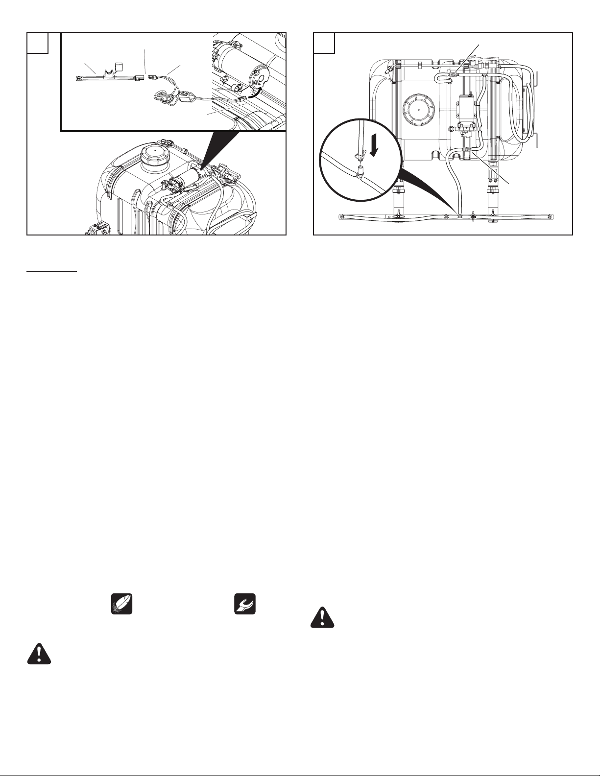
Tighten to no more
than 7.5 ft lbs
4
8
Recirculation Valve
Boom Valve
ENGLISH
SAFETY
1. Read this owners manual and the vehicle owners manual before
using this sprayer.
2. Never allow children to operate this sprayer.
3. Do not allow anyone to ride on or sit on this sprayer.
4. Keep the area clear of all persons, especially small children.
5. Read the chemical label before handling or mixing chemicals.
6. Wear eye and hand protection and protective clothing when
handling and applying lawn chemicals.
7. Always release pressure in the system before lling, cleaning, or
servicing the sprayer.
8. Liquid spray material is recommended. Sprayer does not agitate
wettable powders.
9. Do not spray on windy days.
10. Stop sprayer when tank is empty.
11. Be aware of your vehicle's capabilities. The 45 gallon sprayer
weighs 45 lb (20 kg) empty and 420 lb (191 kg) full.
12. Attaching this sprayer may aect your vehicle's braking and
stability.
13. STAY OFF STEEP SLOPES. Refer to the vehicle owner's manual
concerning safe operation on slopes.
14. Operate at reduced speed on rough terrain, along ditches, and on
hillsides to prevent loss of control.
15. Stopping distance increases with speed and weight. Travel slowly
and allow extra time and distance to stop.
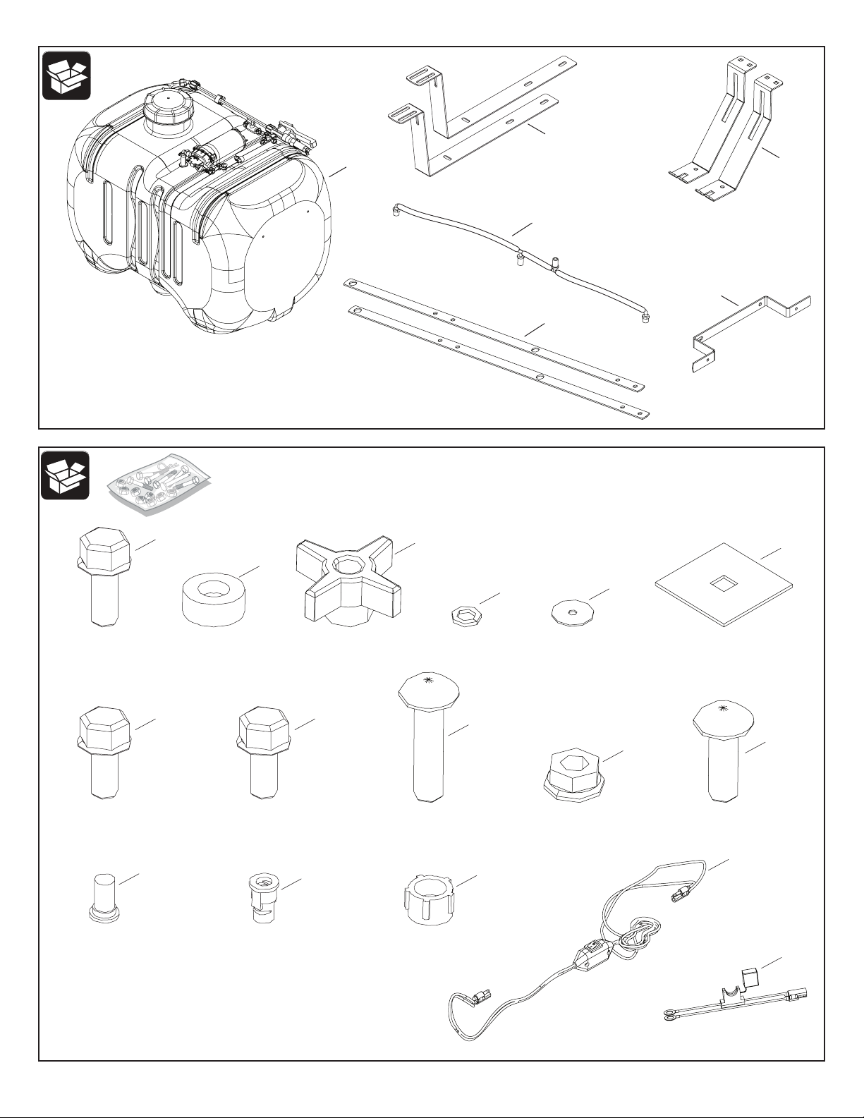
ASSEMBLY
The meanings of symbols used in the illustrations are as follows:
Do not overtighten. Tighten now.
OPERATION
CAUTION: Connect to a 12 V battery only.
PUMP PRESSURE SWITCH
The pump pressure switch turns o the pump when it reaches
its maximum pressure setting. Very low ow demand may cause
the switch to rapidly cycle the pump on and o. Rapid on and o
cycling must be limited to no more than 6 times per minute. Cycling
could cause the motor to heat beyond the recommended maximum
temperature and reduce the operational life of the pump and pressure
switch.
SPRAYER CONTROLS
Boom ON-OFF valve shuts o the ow to the boom nozzles.
ADJUSTABLE SPRAY WAND NOZZLE
Twisting the nozzle will adjust the spray pattern from a cone shaped
mist to a solid stream.
SPRAYER RECIRCULATION
1. The sprayer is equipped with a recirculation valve to aid in material
agitation and pressure control.
2. This valve is in the “open” position when the valve handle is in line
with the hose, “closed” when perpendicular to the hose.
3. Adjusting the recirculation valve between the open/closed positions
will aect the pressure coming through the spray wand.
4. Closed position is full pressure through spray wand.
5. It may be helpful to adjust the pressure when spraying with the
spray wand to avoid damage to plants from excess pressure.
BEFORE STARTING
1. Connect the wire harness from the switch to the pump.
2. Check for leaks using plain water. Fix leaking ttings with thread
tape.
CAUTION: Wear eye and hand protection and protective
clothing when handling and working with lawn chemicals.
PO
7
Install part ST43509 here (Optional)
Install part ST43509 here (Optional)
5
CHECKING MACHINE GROUND SPEED
1. Check ground speed in an open area.
2. Measure a test area that is 30.5 m (100 ft) in length.
3. Operate machine at a low speed and drive the machine the test
distance. Record the time needed to travel that distance.
4. Make three passes, recording the time for each pass. The average
time should be 23 seconds to achieve the recommended operating
speed range.
5. The recommended operating speed is 4.8 km/h (3 mph). At this
speed, the average time traveling the test distance should be 23
seconds.
6. Adjust accordingly to achieve recommended speed range.
GENERAL SPRAYING INFORMATION
The 45 Gallon Sprayer operates at a xed pressure of 620 kPa
(90 psi).This yields 29 minutes of spraying time using the spray
boom or 68 minutes of spraying time using the sprayer wand. When
operating the spray boom, plan on driving about 4.8 km/h (3.0 mph)
or 80 m/min. (264 fpm). That provides 7063 m
2
(76,032 sq ft) of spray
coverage per tank. Plan on about 10 percent overlap, so put enough
chemical in the tank for 6363 m
2
(68.500 sq ft) of spray coverage.
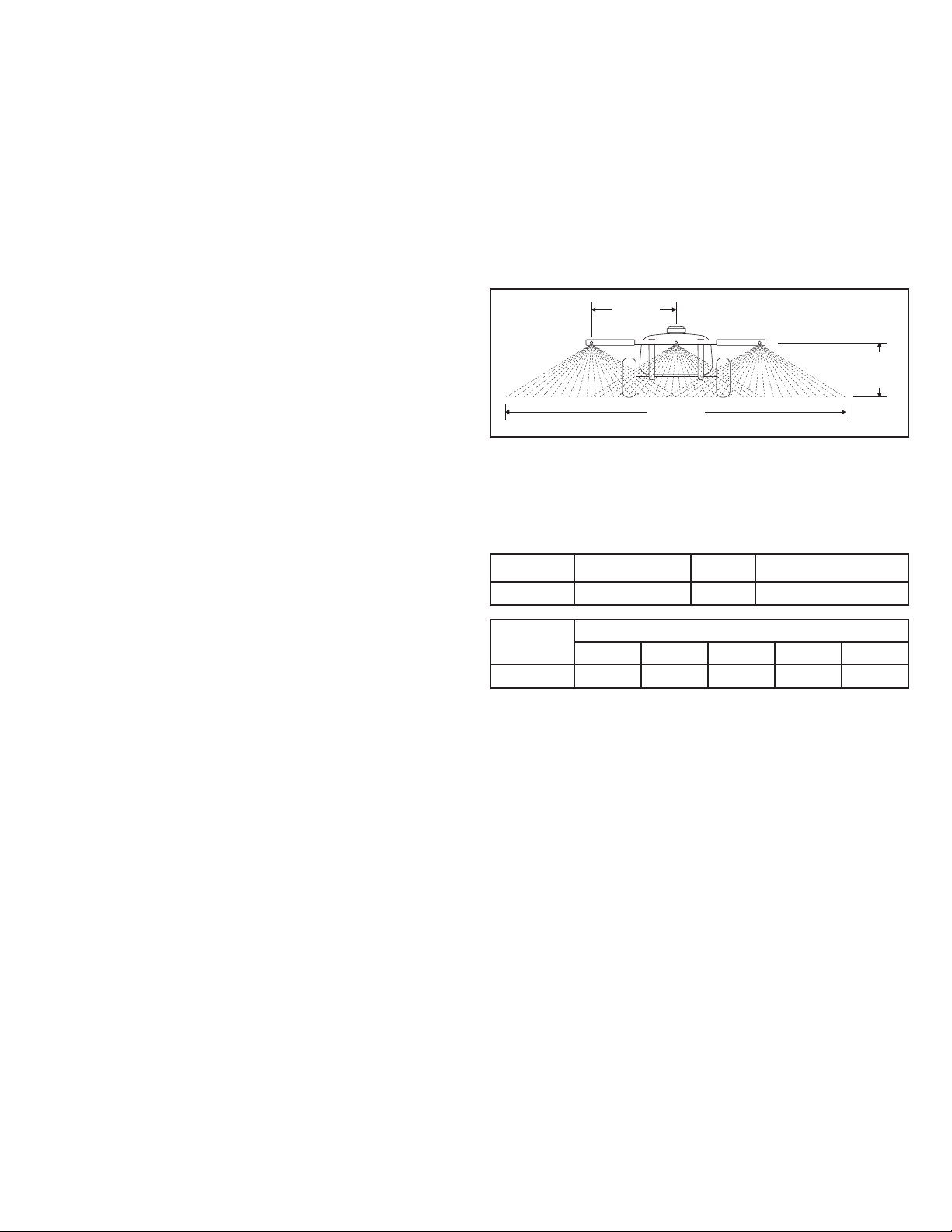
ADJUSTING TIP SPRAY PATTERN
1. Check spray tips:
• Center spray tip should be aligned with boom, and spray
straight back from boom.
• Outer two spray tips should be angled out 30 degrees, as
shown.
2. If necessary, loosen spray tip cap nut. Align spray tip and tighten
cap nut.
3. Test spray pattern with water on driveway or sidewalk, and adjust
as necessary. There should be some spray overlap between each
tip and the spray patterns should be consistent.
SELECTING SPRAY WAND OR BOOM NOZZLES
• To use spray wand: Turn boom valve so that it is perpendicular with
hose. You can now use the spray wand for spraying.
• To use sprayer boom: Turn boom valve so that it is perpendicular
with hose. Turn pump on and operate spray wand to remove all
air from hose. After spray wand sprays liquid, turn pump o. Turn
boom valve so that it is parallel with hose. You can now use the
boom nozzles for spraying.
USING SPRAY WAND
NOTE: Spray wand should only be used when operator is seated.
1. Turn boom valve so that it is perpendicular with hose.
2. Squeeze handle to spray.
3. Push lock forward to lock handle in the on position.
NOTE: Removal of nozzle allows for quick cleaning or rinsing of
sprayer tank.
4. Adjust nozzle:
• Nozzle Angle - Loosen locknut. Turn nozzle as desired and
tighten locknut.
• Nozzle Spray Pattern - To change the spray pattern, tighten or
loosen nozzle as desired.
USING THE BOOM SPRAYER
1. Determine the application rate (gallons per 1,000 sq. feet) based on
the chemical manufacturers recommendations.
2. Estimate the size of the area to be sprayed and the amount of
solution that will be needed. This can help avoid unneeded solution
left in the tank.
3. Refer to the application chart below to help determine the speed
required to achieve the manufacturers recommended application
rate.
4. Use plain water to set the correct boom spraying pressure. Turn
the boom valve to the ON position. If misting occurs, gradually start
closing the valve until misting stops.
5. Add the chemical solution to the tank, following the manufacturers
recommendations.
67 in.
170 cm
20 in.
51 cm
24 in.
61 cm
6. Begin spraying, making each pass so that the spray pattern slightly
overlaps the spray pattern from the previous pass.
7. Stay clear of owers, shrubs, and evergreen trees when spraying to
prevent contact of the solution with these sensitive plants.
APPLICATION CHART
Sprayer Tip Size PSI GMP One Nozzle
45 Gallon TF-VP3 30 0.52
Sprayer Gallons per 1000 Sq. Ft.
2 mph 3 mph 4 mph 5 mph 6 mph
45 Gallon 1.8 1.2 0.88 0.71 0.59
MAINTENANCE
AFTER EACH USE
1. Fill the tank part way with water and pump the water out through
the boom assembly and the spray gun. Use the spray gun to wash
the inside of the tank.
2. Rell the tank about half full with water and a chemical neutralizer
solution and repeat the cleaning instructions above. Follow the
manufacturers instructions for disposal of all chemicals.
AS NEEDED
1. Periodically clean the tank strainer on the end of the intake hose.
Remove the nylon swivel nut from the hose, pull out the screen,
and ush it with water.
2. Periodically clean the strainers in the boom nozzles. Remove the
nozzle, pull out the screen, and ush it with water.
WINTER STORAGE
1. Drain all water out of the sprayer, especially the pump and spray
gun. These items are prone to damage from freezing temperatures.
2. Winterize the sprayer by pumping a 50-50 solution of water and
R.V. antifreeze through the boom assembly and the spray gun.

6
45-0582
38
5
41
6
46
52
15
30
7
51
49
4
45
31
8
47
9
10
16
49
14
24
1
36
48
29
27
26
32
33
28
47
35
20
13
11 11
29 50
2
34
3
36
25
3
44
43
37
26
49
12
2
21
22
23
25
28
33
42
6
40
39

7
45-0582
the fastest way to purchase parts
www.speedepart.com
REF.
NO.
PART
NO.
QTY. DESCRIPTION
1 ST44023 1 45 Gallon Tank
2 ST43495 2 Boom
3 ST43176 8 Rubber Bumper
4 ST43918 1 Pump 12v, 100psi, 2.2GPM
5 2-340 1 Hose, 3/8" x 20'
6 ST43014 2 In-Line Valve 3/8" Barbed
7 ST43235 1 Tee 3/8" Barb - 3/8" Barb
8 ST43258 1 Sump Strainer 3/8"
9 ST43182 1 Sump Fitting 3/8" Barb
10 ST43183 1 Elbow 3/8" Mp - 3/8" Barb
11 ST43192 2 3/8 Barbed Tee, W/ Nut
12 ST43011 2 3/8" Elbow Fitting W/ Nut
13 ST43499 1 3/8" Barb Fitting For Wing Nut
14 ST43175 1 Tank Fill Cap
15 ST43287 1 Spray Wand Holder, Large
16 ST43130 1 Spray Wand Holder, Small
20 ST43498 1 Plastic Wing Nut
21 ST43016 3 Spray Tip Screen
22 ST43410 3 Spray Tip TF-VP3
23 ST43012 3 Tip Fitting Cap Nut
24 ST43516 1 Drain Cap
25 ST43493 2 Tank Support
26 ST43494 2 Boom Support
27 ST43506 2 Square Washer 2"
28 ST43289 4 3/8 Plastic Knob
29 ST65005 4 3/8 X 1-1/2 Carriage Bolt
30 ST65000 2 #10-24 X 3/8" Truss Head
31 ST65001 4 #10-24 X 1" Truss Head
REF.
NO.
PART
NO.
QTY. DESCRIPTION
32 ST65003 2 3/8" Washer
33 ST65004 4 3/8" Lock Washer
34 ST65014 2 5/16 X 1 Flange Bolt
35 ST65006 4 5/16 X 3/4 Carriage Bolt
36 ST65008 6 5/16 Flange Nut
37 ST65007 4 5/16 X 3/4 Flange Bolt
38 ST43652 12 Hose Clamp, 3/8" – 1/2"
39 ST43472 1 Switch Wire Harness
40 ST43483 1 Battery Wire Harness
41 ST43673 1 Spray Wand W/ Tip
42 ST43013 1 3/8 Barbed, Tee
43 ST62006 1 Hose Wrap Bracket
44 ST65011 2 5/16-18 X 5/8" Flange Bolt
45 ST43191 1 Hose Holder 3/8"
46 ST43844 2 Grommet 5/8 ID, 1-1/8 OD, 7/8
47 2-314 1 Hose, 3/8" x 22"
48 2-323 1 Hose, 3/8" x 48"
49 2-318 3 Hose, 3/8" x 12"
50 2-319 1 Hose, 3/8" x 8.5"
51 2-342 1 Hose, 3/8" x 3.25"
52 2-321 1 Hose, 3/8" x 6.5"
- ST43684 1 Washer For Drain Cap*
- ST44017 1 Lanyard For Tank Fill Cap*
- 3-70 1 Label, Terra-King*
- ST43523 1 Label, 45 Gallon*
- ST43488 1 Label, Warning - Chemical Hazard*
- ST43509 1 Wire Harness Extension 8'*
- 3-177 1 Owners Manual*
* Not Shown
ADDITIONAL SERVICE PARTS
PART
NO.
DESCRIPTION
ST43921 Pump Head 2.2 GPM, 100 PSI
ST44032 Pressure Switch 80 PSI
ST50749 15a ATO/ATC Fuse
ST43124 Spray Wand Valve
ST43514 Spray Wand Brass Tip
ST43515 Spray Want Extension

REPAIR PARTS
Agri-Fab, Inc.
809 South Hamilton
Sullivan, IL. 61951
800-448-9282
www.agri-fab.com
the fastest way to purchase parts
www.speedepart.com
© 2022 Agri-Fab, Inc.
This document (or manual) is protected under the U.S. Copyright Laws and the copyright laws of foreign countries, pursuant to the Universal
Copyright Convention and the Berne convention. No part of this document may be reproduced or transmitted in any form or by an means,
electronic or mechanical, including photocopying or recording, or by any information storage or retrieval system, without the express written
permission of Agri-Fab, Inc. Unauthorized uses and/or reproductions of this manual will subject such unauthorized user to civil and criminal
penalties as provided by the United States Copyright Laws.
Table of contents
Popular Farm Equipment manuals by other brands

Schaffert
Schaffert Rebounder Mounting instructions

Stocks AG
Stocks AG Fan Jet Pro Plus 65 Original Operating Manual and parts list

Cumberland
Cumberland Integra Feed-Link Installation and operation manual

BROWN
BROWN BDHP-1250 Owner's/operator's manual

Molon
Molon BCS operating instructions

Vaderstad
Vaderstad Rapid Series instructions


