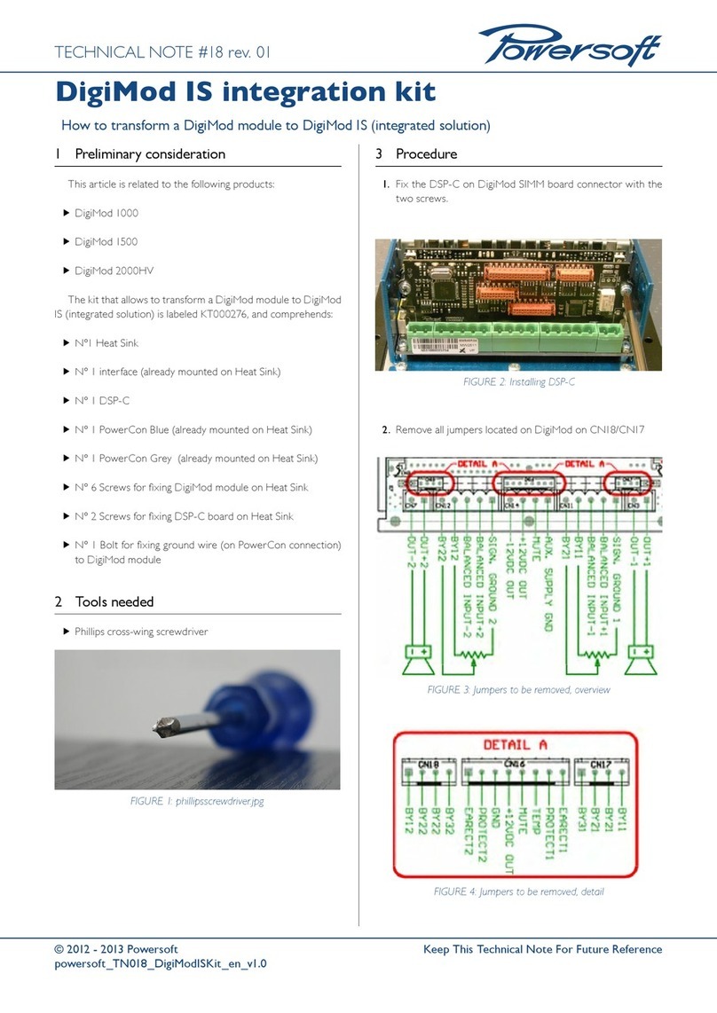
Terranova Scientific 921 User manual

DUNIWAY STOCKROOM CORP.
WWW.DUNIWAY.COM
1 of 22
Instruction Manual
Terranova Scientific Model 921
Cold Cathode Gau
g
e Controller
for use with HPS Inverted Magnetron Vacuum Gauges
Copyright © 1998 by Terranova Scientific, Inc.
All rights reserved, including the right of reproduction in whole or part in any form, without
permission in writing from Terranova Scientific, Inc.
TELEPHONE: 650-969-8811 TOLL-FREE (U.S. only): 800-446-8811 FAX: 650-965-0764 EMAIL: [email protected]
www.duniway.com

DUNIWAY STOCKROOM CORP.
WWW.DUNIWAY.COM
2 of 22
Table of Contents
I Overview page 7
A. General Description
B. Specifications
II Installation page 9
A. Unpack the Controller
B. Mount the Controller
C. Select the Gauge Tube
D. Connect the Gauge Tube
E. Attach the Gauge Cable
F. Make Relay Connections
G. Make Accessory Connections
H. Check Supply Voltage
I. Attach the Power Cord
III Operation page 12
A. Turn Power On
B. Front Panel Controls
C. Analog Output
D. Serial Interface
IV Maintenance page 17
A. Changing Fuses
B. Schematic Diagrams
TELEPHONE: 650-969-8811 TOLL-FREE (U.S. only): 800-446-8811 FAX: 650-965-0764 EMAIL: [email protected]
www.duniway.com

DUNIWAY STOCKROOM CORP.
WWW.DUNIWAY.COM
3 of 22
V Troubleshooting page 18
VI Return Procedure page 19
VII Warranty page 20
Application Alert page 22
List of Fi
g
ures
Figure 1: Model 921 Front Panel page 5
Figure 2: Model 921 Rear Panel page 5
Figure 3: Model 921 Rear Panel, CE Model page 6
Figure 4: Model 921 Dimensions page 6
Table 1: Accessory Connector Pin Assignments page 11
TELEPHONE: 650-969-8811 TOLL-FREE (U.S. only): 800-446-8811 FAX: 650-965-0764 EMAIL: [email protected]
www.duniway.com

DUNIWAY STOCKROOM CORP.
WWW.DUNIWAY.COM
4 of 22
Safety Information
High Voltage
WARNING!
The Terranova 921 Cold Cathode Gauge Controller supplies a high voltage
of 4,000 volts to the HPS Inverted Magnetron Gauge Head when the “Hi
Volt Gauge on” is activated. Be sure that the Hi Volt light is off and/or that
the power is removed from the Terranova 921 Controller before connecting
or disconnecting either end of the gauge cable.
Combustible Gases
WARNING!
Do not use the Terranova 921 Cold Cathode Gauge Controller / Display to
measure the pressure of combustible gas mixtures. The gauge operates with
an ionized gas discharge, and it is possible that this discharge may cause ig-
nition of combustible mixtures, which then might explode and cause dam-
age to equipment and injury to personnel.
Chemicals
WARNING!
Many organic cleaning solvents, such as acetone, produce fumes that are
toxic or flammable. Use such solvents only in areas that are well ventilated
to the outdoors and away from electronic equipment, open flames, or other
potential ignition sources.
TELEPHONE: 650-969-8811 TOLL-FREE (U.S. only): 800-446-8811 FAX: 650-965-0764 EMAIL: [email protected]
www.duniway.com

DUNIWAY STOCKROOM CORP.
WWW.DUNIWAY.COM
5 of 22
Figure 1: Model 921 Front Panel
Figure 2: Model 921 Rear Panel
ser. no.
3
10
TELEPHONE: 650-969-8811 TOLL-FREE (U.S. only): 800-446-8811 FAX: 650-965-0764 EMAIL: [email protected]
www.duniway.com

DUNIWAY STOCKROOM CORP.
WWW.DUNIWAY.COM
6 of 22
Figure 3: Model 921 Rear Panel, CE Model
Figure 4: Model 921 Dimensions
ser. no.
3.80 inch
96.5 mm 6.5 inch
165 mm
1.85 inch
47 mm
3.60 inch
91.4 mm
1.78 inch
45.2 mm
Mounting Cutout
TELEPHONE: 650-969-8811 TOLL-FREE (U.S. only): 800-446-8811 FAX: 650-965-0764 EMAIL: [email protected]
www.duniway.com

DUNIWAY STOCKROOM CORP.
WWW.DUNIWAY.COM
7 of 22
I Overview
A. General Description
The Terranova Scientific Model 921 Cold Cathode Gauge Controller displays vacuum pressure
as measured from an HPS inverted magnetron gauge tube. It displays vacuum measurements
based on ionization of the residual gas. The Model 921 controller covers the range from 3 x 10-
10 Torr (mbar) to 10-2 Torr (mBar), and controls two relays with independent set points.
B. Specifications
1. Useful Measuring Range
3 x 10⁻¹⁰ Torr (mBar) to 10-2 Torr (mBar), for air or nitrogen; range selection is automatic
2. Display Range
3 x 10⁻¹⁰ Torr (mBar) to 10-2 Torr (mBar)
3. Units of Display
torr or mBar; user selectable
4. Vacuum Gauge
HPS Inverted Magnetron gauges, series 421 or I-Mag®, series 423.
5. Operating Temperature Range
+2 to +50 deg. Celsius
6. Pressure Display
4-digit bright LED, 10 mm high
7. Display Indicators
red LED for set points and other parameters
8. Process Control Set Points
two, adjusted by front panel push-button
9. Process Control Relays
two relays, 2 amp, 240 VAC contacts; independent Normally Open and Normally Closed; +5
volts is provided for TTL applications; available through the D15 accessory connector
10. Nonvolatile Memory
for all user adjusted parameters
I-Mag® is a registered trademark of MKS Instruments Inc.
TELEPHONE: 650-969-8811 TOLL-FREE (U.S. only): 800-446-8811 FAX: 650-965-0764 EMAIL: [email protected]
www.duniway.com

DUNIWAY STOCKROOM CORP.
WWW.DUNIWAY.COM
8 of 22
11. Analog Output
calibrated, 12-bit resolution, logarithmic, 0.50 volts/decade
12. RS-232 Input/Output
allows user to read pressure and set points; 9600 baud, 8-N-1; available through the D15 acces-
sory connector
13. Operating Voltage
the Model 921 has a universal power supply, which operates on input voltages from 85 VAC to
265 VAC 50/60 Hz; standard IEC 320 instrument power input receptacle on rear panel; replace-
ment fuse type: 5 mm X 20 mm, regular 1 amp
manufacturer fuse type
Bussman GDB-1A or GDC-1A
Littlefuse 217 001 or 218 001
14. Weight
1 lb. / 0.5 kg
15. Mounting
Side clips are provided for panel mounting in standard 1/8 DIN cutout.
16. Environmental Considerations
not for use with explosive or corrosive gases
17. Vacuum gauge tube:
the HPS Cold Cathode (Inverted Magnetron) and cable are available from Duniway Stockroom
or HPS:
Duniway Stockroom
tel (800) 446-8811 or (650) 969-8811 (California)
Facsimile (650) 965-0764
Inverted Magnetron Gauge: Duniway part no. IMAG-CFF
Inverted Magnetron Cable: Duniway part no. IMAG-CBL
HPS Division of MKS Instruments
tel. (800) 345-1967; (303) 449-9861 (Colorado)
Facsimile (303) 442-6880
TELEPHONE: 650-969-8811 TOLL-FREE (U.S. only): 800-446-8811 FAX: 650-965-0764 EMAIL: [email protected]
www.duniway.com

DUNIWAY STOCKROOM CORP.
WWW.DUNIWAY.COM
9 of 22
II Installation
A. Unpack the Controller
Carefully unpack the Model 921 Gauge Controller.
The gauge controller shipment includes these components:
• controller unit
• power cord
• mounting clips
• D15 accessory connector
• this instruction manual
If your controller does not have all of these items, call Duniway Stockroom. If it appears to have
been damaged in shipment, contact the shipper.
B. Mount the Controller
You can mount the controller unit freestanding on a bench, table top, or shelf, or you can mount
it in a rack or cabinet. The controller unit is housed in a standard 1/8 DIN box.
If you are mounting the unit in a panel, the cutout dimensions are 44 mm by 92 mm. One mount-
ing clip attaches to each of the sides of the controller unit. To attach the clip, slide the beveled
surfaces of the clip under the cutout on the side of the box and push the clip toward the back of
the unit until the central tongue locks the clip in place. Then slide the unit into the panel; the clips
will hold the unit in place.
Be sure to leave enough clearance at the back of the controller unit for easy access to cable con-
nections.
C. Select the Gauge Tube
The Model 921 controller is designed to work with the HPS Inverted Magnetron gauge tube, se-
ries 421 or I-Mag. See Specifications for availability of gauges. If you have difficulty obtaining
a gauge, please contact us at Duniway Stockroom.
CAUTION
Use of a gauge tube other than those listed above may cause improper
readings, and may cause damage to the gauge tube.
TELEPHONE: 650-969-8811 TOLL-FREE (U.S. only): 800-446-8811 FAX: 650-965-0764 EMAIL: [email protected]
www.duniway.com

DUNIWAY STOCKROOM CORP.
WWW.DUNIWAY.COM
10 of 22
D. Connect the Gauge Tube
Make sure that the gauge tube is securely connected to the vacuum system, using good vacuum
practice.
E. Attach the Gauge Cable
The gauge cable has a two coaxial connectors for the gauge. One is a high voltage BNC (SH-
VBNC); this connector is for the 4000 volt anode excitation of the gauge. The smaller connector
is an SMB coaxial connector, for the collector signal.
Connect both connectors of the gauge cable to the gauge tube and to the 921 controller.
NOTE
If you have an HPS cable for this series of gauges, you may use it with your
Model 921 gauge controller, since connectors are the same as for the HPS
instruments.
F. Make Relay Connections
You can set two process control set points from the front panel of the controller (SET PT 1) and
(SET PT 2). The set points control two relays that are accessible through the connector on the back
of the controller. SET PT 1 controls relay #1, and SET PT 2 controls relay #2. Relay contacts are
available through the D15 Accessory Connector. See Table 1, below on page 11.
G. Make Accessory Connections
The 15-pin D-sub Accessory Connectoris on the rear panel of the 921, see Table 1, below on page
11. The connector has female pins; the mating connector must have male pins. Mating D-sub 15
connectors are available from many of the normal electronic sources. If you need help identifying
a source, please contact us.
H. Check Supply Voltage
The Model 921 incorporates a universal power supply. This allows the 921 to operate on any input
voltage from 90 VAC to 265 VAC, 47 to 65 Hz.
I. Attach the Power Cord
Plug the power cord into the receptacle in the power module on the rear of the 921.
TELEPHONE: 650-969-8811 TOLL-FREE (U.S. only): 800-446-8811 FAX: 650-965-0764 EMAIL: [email protected]
www.duniway.com

DUNIWAY STOCKROOM CORP.
WWW.DUNIWAY.COM
11 of 22
Table 1 Accessory Connector Pin Assignments
Following are the pin assignments for the Accessory Connector:
15-Pin-D Si
g
nal Function
pin 1 Set Point #1 relay, normally closed
pin 2 Set Point #1 relay, common
pin 3 Set Point #1 relay, normally open
pin 4 Set Point #2 relay, normally closed
pin 5 Set Point #2 relay, common
pin 6 Set Point #2 relay, normally open
pin 7 Tx, RS-232 signal out of the 921, 9600-N-8-1
pin 8 Rx, RS-232 signal into the 921
pin 9 Ground, RS-232 and analog common
pin 10 no function
pin 11 no function
pin 12 no function
pin 13 Analog Output, 1Kohm, 0.5 volts per decade
pin 15 no function
pin 16 no function
TELEPHONE: 650-969-8811 TOLL-FREE (U.S. only): 800-446-8811 FAX: 650-965-0764 EMAIL: [email protected]
www.duniway.com

DUNIWAY STOCKROOM CORP.
WWW.DUNIWAY.COM
12 of 22
III Operation
A. Turn Power On
Plug the AC power end of the power cord into an electrical outlet. The loudspeaker will “beep”
and test all indicators while the controller executes its self test. After being turned on, the instru-
ment will go through the following sequence:
• “beeper”
• indicators for TORR, MBAR
• 10 LED indicators for set points and other functions
• all four digits will light, including decimal points
• display shows the model number of the instrument, 921
• display shows software version, e.g. 1.01
Following the initial self-test, the display will show OFF. This indicates the high voltage for the
anode has not been applied.
B. Front Panel Controls
The Model 921 allows flexible configuration of operation using simple entry from the front panel
buttons labeled GAUGE ON/OFF, SELECT, RAISE and LOWER. Parameters which you may adjust are
selected by scrolling through the list which begins withSET PT 1 HIGH. Each time the SELECT but-
ton is pushed, the led indicator advances to the next parameter. The LED indicators will be lit to
indicate which parameter is being adjusted, and the digital display will flash to indicate the value
of the parameter being adjusted.
Each push of a button will give a short “beep” from the loudspeaker to confirm the button was
pushed. If you have reached the limit of adjustment or if the button push is not allowed, the loud-
speaker will give a long “beep”.
Following is detail description of the parameter selection and adjustment:
1. Set Pt 1 High
This sets the high limit of the set point. Above this pressure, the set point relay will be de-ener-
gized. Press the RAISE and LOWER buttons to enter the value desired. The minimum value is OFF;
this shuts the set point off. The next increment is to 1.1 x 10⁻⁹ Torr.
When the RAISE or LOWER buttons are pressed, the display will change slowly at first. If you hold
the button down for a few seconds, the rate of change will increase to allow you to make large
changes more quickly.
SET PT 1 HIGH operates in conjunction with SET PT 1 LOW. While the 921 is in this mode, the set
point may be assigned to either GAGE 1 or GAGE 2 by pressing the GAUGE SELECT button.
2. Set Pt 1 low
This sets the low limit of the set point. This is the pressure at which the set point relay will be
energized. Operation is similar to that of SET PT1 HIGH above. The minimum value is OFF; this
TELEPHONE: 650-969-8811 TOLL-FREE (U.S. only): 800-446-8811 FAX: 650-965-0764 EMAIL: [email protected]
www.duniway.com

DUNIWAY STOCKROOM CORP.
WWW.DUNIWAY.COM
13 of 22
shuts the set point off. The next increment is to 1.0 x 10⁻⁹ Torr.
SET PT 1 LOW operates in conjunction with SET PT 1 HIGH.
NOTE
The High and Low set point allow the user to set the hysteresis of the set
point operation. As the system is pumped down, the set point relay will be
energized (set point turns on) as the pressure drops below SET PT 1 LOW. The
relay will remain energized until the pressure rises above SET PT 1 HIGH.
It is not possible to adjust the High set point to be lower than the Low set
point. If you adjustthe High set point below the pressure previouslyselected
for the Low set point, the 921 will automatically reduce the value for the
Low set point so that it is the next increment lower than that of the High set
point.
3. Set Pt 2 High
This operates in the same manner as SET PT 1 HIGH, described above.
4. Set Pt 2 Low
This operates in the same manner as SET PT 1 LOW, described above.
5. Torr/mBar
This allows selection of the units to be used in display of the pressure. Press either the RAISE or
LOWER buttons to alternate between Torr and mBar.
6. Calibrate
This allows the user to modify the reading for either gauge by multiplying by a value between
0.500 and 2.000. This is convenient for calibration of the gauge or for making adjustments for
different gas factors. We suggest you use this adjustment only if you have reliable calibration da-
ta. The multiplier is internal, and is not seen by the user. The digital display shows the result of
the pressure multiplied by the internal multiplier.
7. Reset of Stored Values
This allows you to recover the factory settings for all stored values and resets the SET POINTS to
off. For a system that is far out of calibration, the factory settings provide a good starting point
for re-calibrating or adjusting the gauge controller. To recover the factory settings, unplug the 921
from its power source. Press and hold RAISE and LOWER buttons at the same time; while holding
the RAISE and LOWER buttons depressed, plug the power cord in. You will hear a few short
‘chirps’ from the loudspeaker confirming the factory settings have been entered. The digital dis-
play will show RST to confirm the reset has been entered.
8. Set Point Operation
See description of operation under Front Panel Controls.
TELEPHONE: 650-969-8811 TOLL-FREE (U.S. only): 800-446-8811 FAX: 650-965-0764 EMAIL: [email protected]
www.duniway.com

DUNIWAY STOCKROOM CORP.
WWW.DUNIWAY.COM
14 of 22
9. Reading Pressure
Pressure display and ranging are automatic in the 921. Most readings will take place between zero
pressure and the full scale of the 921. For pressure lower than the minimum capability of the 921,
the display will show -LO. For pressure greater than the maximum full scale of the 921, the dis-
play will show HI.
C. Analog Output
The analog output is calculated from the value of the digital display. The output is logarithmic,
0.5 volt/decade; the source impedance for the output is 1 K ohm. The output voltage is calculated
from:
V=0.50*(lo
g
10(1010*Pressure))
where V is the Analog Output in volts; P is the pressure in Torr or mbar.
Some examples follow; because of normal tolerances in the electronics, there may be minor dif-
ferences in the values you observe compared to those shown:
displayed pressure Analog Output - volts
OFF or OP 0.00
1.0 x 10⁻¹⁰ Torr (mBar) or less 0.00
1.0 x 10⁻⁹ Torr (or mBar) 0.50
3.0 x 10⁻⁹ 0.74
1.0 x 10⁻⁸ 1.00
1.0 x 10⁻⁷ 1.50
1.0 x 10⁻⁶ 2.00
1.0 x 10⁻⁵ 2.50
1.0 x 10⁻⁴ 3.00
1.0 x 10⁻³ 3.50
1.0 x 10⁻² 4.00
The pressure as a function of the Analog Output voltage is:
P=10-10*lo
g
-1(2V)or
P=10-10*10(2V) Torr (or mbar)
where P is pressure in mTorr or µbar; V is the Analog Output in volts.
TELEPHONE: 650-969-8811 TOLL-FREE (U.S. only): 800-446-8811 FAX: 650-965-0764 EMAIL: [email protected]
www.duniway.com

DUNIWAY STOCKROOM CORP.
WWW.DUNIWAY.COM
15 of 22
Analog Output - volts pressure
0.10 1.6 x 10⁻¹⁰ Torr (or mbar)
0.50 1.0 x 10⁻⁹
1.00 1.0 x 10⁻⁸
1.10 1.6 x 10⁻⁸
2.00 1.0 x 10⁻⁶
3.50 1.0 x 10⁻³
4.00 1.0 x 10⁻²
NOTE
The analog output is valid for the gauge which is selected on the display.
D. Serial Interface
The RS-232 serial port gives pressure readings when requested by the terminal. The interface is
standard RS-232 format; 9600 baud, 8-bits, no parity, 1 stop bit. The interface is through the 15-
pin D-sub accessory connector, see fig. 2, page 4 and fig. 3, page 5.
pin 7 is Tx (signal from the 921 to the terminal)
pin 8 is Rx (signal from the terminal to the 921)
pin 9 is return (ground).
The serial port allows reading pressure and other parameters of the 921; it is not possible to mod-
ify stored parameters over the serial port.
The following commands are used in the 921:
1. Pressure
To read the pressure:
Send “p” (ASCII value 112); the 921 sends pressure to the terminal. Output is in the format:
A.Be-C
where A.B is the multiplier and -C is the exponent
Some examples follow:
displayed pressure Serial Output
OFF Off
OP Open (lower than 1.0 x 10⁻¹⁰)
1.0 x 10⁻⁹ Torr 1.0e-9
3.4 x 10⁻⁸ Torr 3.4e-8
TELEPHONE: 650-969-8811 TOLL-FREE (U.S. only): 800-446-8811 FAX: 650-965-0764 EMAIL: [email protected]
www.duniway.com

DUNIWAY STOCKROOM CORP.
WWW.DUNIWAY.COM
16 of 22
2. Units of Measurement
To read the chosen units of measure for the gauge:
Send “u” (ASCII value 117); the 921 returns
Torr or mBar
3. Set Point #1
To read the setting and status of set point #1
Send “1” (ASCII value 49); the 921 returns information for set point #1 in the format:
STUeVWXY
eZA B
where:
STU is the multiplier and V is the exponent for set point #1 high
WXY is the multiplier and Z is the exponent for set point #1 low
Ais the gauge to which the set point #1 has been assigned: either 1 or 2
Bis set point relay status; 0= relay is not energized, 1=relay is energized
4. Set Point #2
To read the setting and status of set point #2
Send “2” (ASCII value 50); the 921 returns information for set point #2 in the same format as for
set point #1, above.
5. Model and Software Revision
To read software identification.
Send “v” (ASCII value 118); the 921 returns the model number of the instrument and the revision
number, as in the following example:
921 ver 1.02
6. High Voltage Control: ON (version 1.08 and later only)
To turn the High Voltage On:
Send “n” (ASCII value 110); the 921 returns “OK” to acknowledge receipt of the command. The
921 turns the high voltage on and begins measurement of pressure in the same manner as if the
front panel High Voltage button had been pressed.
7. High Voltage Control: OFF (version 1.08 and later only)
To turn the High Voltage Off:
Send “f” (ASCII value 102); the 921 returns “OK” to acknowledge receipt of the command. The
921 turns the high voltage off in the same manner as if the front panel High Voltage button had
been pressed. The 921 display will show “OFF”.
TELEPHONE: 650-969-8811 TOLL-FREE (U.S. only): 800-446-8811 FAX: 650-965-0764 EMAIL: [email protected]
www.duniway.com

DUNIWAY STOCKROOM CORP.
WWW.DUNIWAY.COM
17 of 22
IV Maintenance
A. Changing Fuses
The controller contains two fuses. Both fuses are held in the fuse assembly that is part of the pow-
er module located on the back panel of the controller. To change fuses, unplug the line cord from
the power entry module at the rear of the 921; locate the fuse block immediately below the line
cord socket. Press the tab of the fuse assembly and withdraw the fuse assembly from the power
module.
Turn the fuse assembly around so that the fuses are facing you. Check both fuses; replace the
burnt-out fuse with a fuse of the appropriate rating (refer to Specifications section). Reinsert the
fuse assembly into the power module; push it in until the ears click into place.
Replacement fuse type: 5 mm X 20 mm, regular 1 amp
manufacturer fuse type
Bussman GDB-1A or GDC-1A
Littlefuse 217 001 or 218 001
B. Schematic Diagrams
Because of the proprietary nature of our products, we do not supply schematic diagrams or soft-
ware listings. If you have any problem with operation or interface to any of our products, please
contact us; we will do everything we can to serve your needs.
TELEPHONE: 650-969-8811 TOLL-FREE (U.S. only): 800-446-8811 FAX: 650-965-0764 EMAIL: [email protected]
www.duniway.com

DUNIWAY STOCKROOM CORP.
WWW.DUNIWAY.COM
18 of 22
V Troubleshooting
If the self-test fails, run the self-test again by turning the power off and then on again. If it fails
again, call Duniway Stockroom.
If fuses burn out, check to see that the proper voltage has been supplied to the power input
module.
If fuses burn out repeatedly call Duniway Stockroom.
TELEPHONE: 650-969-8811 TOLL-FREE (U.S. only): 800-446-8811 FAX: 650-965-0764 EMAIL: [email protected]
www.duniway.com

DUNIWAY STOCKROOM CORP.
WWW.DUNIWAY.COM
19 of 22
VI Return Procedure
If you need to return the gauge controller for service, first contact Duniway Stockroom to get au-
thorization. Then pack the instrument securely. Use the original packaging if it is available. If you
do not have appropriate packing materials, a commercial packing and shipping firm can provide
them.
Notes
TELEPHONE: 650-969-8811 TOLL-FREE (U.S. only): 800-446-8811 FAX: 650-965-0764 EMAIL: [email protected]
www.duniway.com

DUNIWAY STOCKROOM CORP.
WWW.DUNIWAY.COM
20 of 22
VII Warranty
Terranova products of Duniway Stockroom Corp. are warranted to be free of defects in
material and workmanship for a period of one year from the date of shipment. At our
option, we will repair or replace products which prove to be defective during the war-
ranty period. Liability under this warranty is limited to repair or replacement of the
defective items. Shipping damage is excluded from the scope of this warranty. Gauge
tubes of all types are excluded from this warranty.
Terranova products are warranted not to fail to execute programming instructions due
to defects in materials and workmanship. If Duniway Stockroom receives notice of such
defects during the warranty period. Duniway Stockroom will repair or replace firmware
that does not execute its programming instruction due to such defects. Duniway Stock-
room does not warrant that the operation of the firmware or hardware will be uninter-
rupted or error-free.
If this product is returned to Duniway Stockroom for warranty service, Buyer will pre-
pay shipping charges and will pay all duties and taxes for products returned to Duniway
Stockroom. Duniway Stockroom will pay for return of products to Buyer, except for
products returned to a Buyer from a country other than the United States.
LIMITATION OF WARRANTY:
The foregoing warranty does not apply to the defects resulting from:
1. Improper or inadequate maintenance by Buyer;
2. Buyer-supplied interfacing;
3. Unauthorized modification or misuse;
4. Operation outside of the environmental specifications of the product; or
5. Improper site preparation and maintenance.
THE WARRANTY SET FORTH ABOVE IS EXCLUSIVE AND NO OTHER WARRANTY,
WHETHER WRITTEN OR ORAL, IS EXPRESSED OR IMPLIED. DUNIWAY STOCK-
ROOM DISCLAIMS ANY IMPLIED WARRANTIES OF MERCHANTABILITY AND
FITNESS FOR A PARTICULAR PURPOSE.
EXCLUSIVE REMEDIES: The remedies provided herein are Buyer’s sole and exclusive
remedies. In no event will Duniway Stockroom be liable for direct, indirect, special,
incidental, or consequential damages, including loss of profits, whether based on con-
tract, tort, or any other legal theory.
TELEPHONE: 650-969-8811 TOLL-FREE (U.S. only): 800-446-8811 FAX: 650-965-0764 EMAIL: [email protected]
www.duniway.com
Table of contents
