Terratek TDP13 User manual

User Manual - Please
read and retain for future
reference.
See page 1
Guide d’utilisation
– Veuillez lire et
conserver ceguide
pour vous y reporter
ultérieurement.
Voir page 16
Manual del usuario –
Por favor lea este
manual y guárdelo para
referencia futura.
Ver la págeina 29
5 Speed Drill Press
Perceuse à colonne à 5 vitesses
Prensa Taladradora con 5 Velocidades
TDP13
227541

Exploded Assembly Diagram
Vue éclatée
Dibujo despiezado del conjunto
NOTICE: Actual product may vary from pictures shown.
NOTIFICATION: Le produit réel peut varier des images montrées
AVISO: El producto real puede variar de los cuadros mostrados.
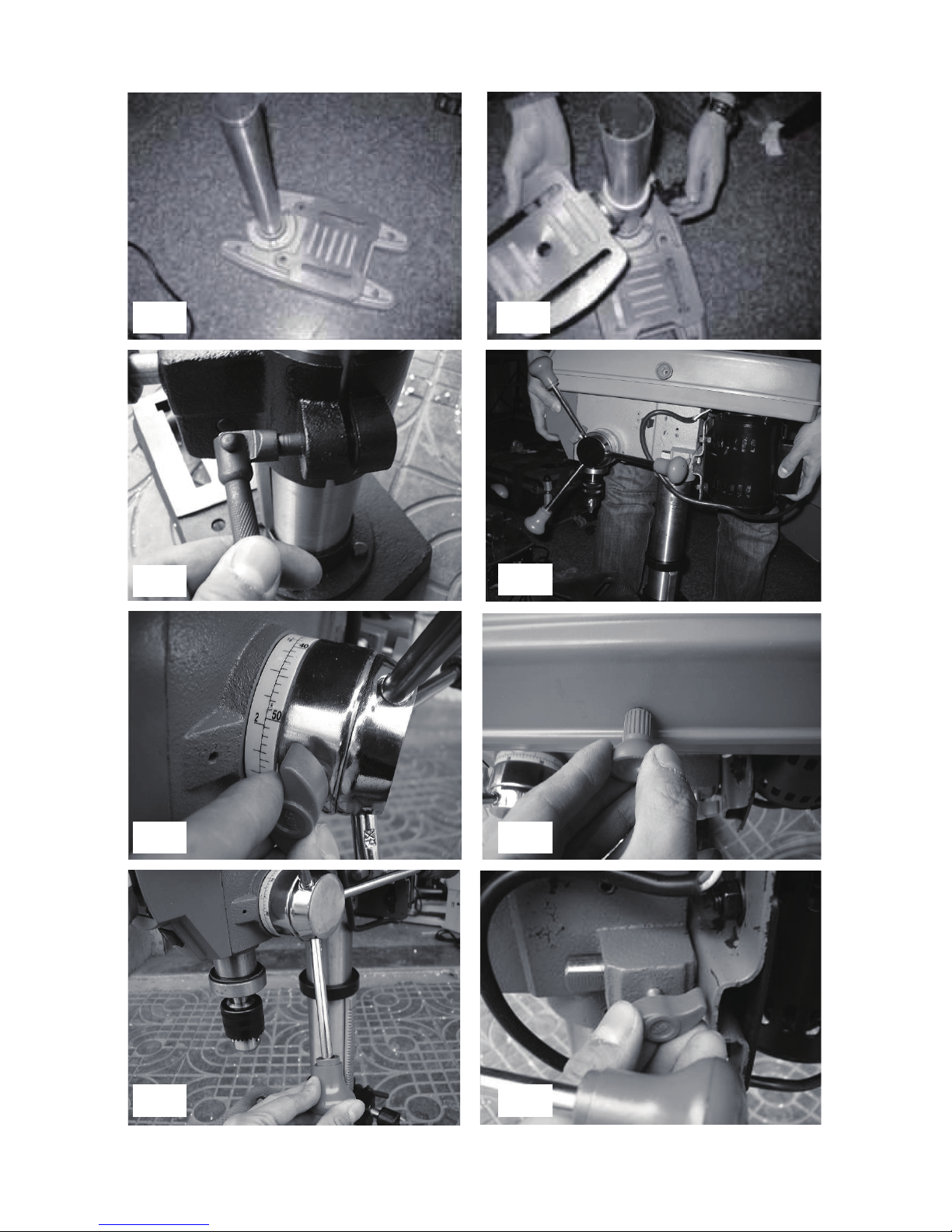
Fig.1 Fig.2
Fig.3 Fig.4
Fig.5
Fig.7
Fig.6
Fig.8

1
Contents
Parts List
Technical Spec.
Safety Instructions
Assembly
Using drill press
Maintenance
Warranty
Parts List
1 Base 32 Washer 4
2 Column Support 33 Switch board
3 Washer 8 34 Nut M10×1
4 Elastic washer 35 Spring cover
5 Bolt M8×20 36 Spring cap
6 column 37 point
7 screw 38 Limit bolt
8 Nut M8 39 Gauge seat
9 Allen hex head bolt 40 Nut M6
10 Locking knob 41 Transformer
11 Gear shaft 42 LED light
12 Handle bar 43 Clamping handle
13 Knob 44 Base
14 spring 45 rivet 2×3
15 Slide bar 46 Angle label
16 Damping pad 47 Work table
17 Rubber pad 48 Bolt M12×25
18 Screw M6×12 49 Elastic washer
19 Washer 6 50 chuck
20 Bolt M8×18 51 spindle
21 Motor pulley 52 Ball bearing
22 Screw M6×10 53 Spindle sleeve
23 V-belt K-660 54 Rubber gasket

2
24 Knob 55 Retaining Ring 12
25 Pulley cover 56 Retaining Ring 40
26 eyeglass 57 Spindle sleeve
27 Power cord 58 Ball bearing
28 Toggle switch 59 Retaining Ring
29 Little switch 60 Spindle pulley
30 Take-up 61 Machine body
31 Screw M4×10 62 Induction motor

3
Technical Information
Voltage: 120V ~ 60Hz
Power: 2.4 amp
Speed: 760 to 3070 RPM
Max Spindle Travel: 2” (50mm)
Chuck Size: ½” (13mm)
Drilling Capacity: ½” (13mm)
Chuck to Table Max. Distance: 9-1/2”
Chuck to Base Max. Distance: 14”
Table Size: 7” Square
Table Adjustment: 0/45 Deg. Tilt (left & right)
360 Degrees Swivel.
Net Weight: 36/40 lbs
Copyright© 2012 by ACL Group Ltd. All rights reserved. This manual or any
artwork contained herein must not be reproduced in any shape or form without
the express written consent of ACL Group Ltd. Diagrams within this manual may
not be drawn proportionally. Due to continuing improvements, actual product
may differ slightly from the product described herein.
Read this entire manual before using this product.
Failure to do so can result in serious injury. Save this manual
for future reference.

4
Read and Keep This Manual
Important SAFETY Information
General Safety Rules
Please read carefully all instructions within this manual. Failure to follow all safety
warnings can result in serious personal injury. The term “Power Tool” in all of the
following warnings refers to your main operated (corded) or battery operated (cordless)
power tool.
WARNING! Read all instructions. Failure to follow all instructions listed below may
result in electric shock, re and/or serious injury. The term “power tool” in all of the
warnings listed refers to corded or cordless power tools.
Work area safety
Keep work area clean and well lit. Cluttered or dark areas invite accidents.
Do not operate power tools in explosive atmospheres, such as in the presence of
ammable liquids, gases or dust. Power tools create sparks which may ignite the dust
or fumes.
Keep children and bystanders away while operating a power tool. Distractions can
cause you to lose control.
Electrical safety
Before use, ensure that the power outlet you are using matches the plug on your
power tool and that the voltage of the outlet matches that of your power tool.
Only use grounded extension cords with power tools tted with 3 pin plugs and if using
outdoors ensure any extension cord is suitable for outdoor use.
Always try to avoid body contact with grounded surfaces, such as radiators, cooking
ranges and any other xed appliance with metal surfaces.
Do not expose your power tool to wet or damp conditions and NEVER use in rain.
Check regularly the power cord of your machine and any extension cord that you are
using for damage.
Do not carry or pull the machine with the power cord.
Ensure the cord is clear from hot surfaces, oil or sharp objects.
This symbol is to warn you of potential personal
injury hazards. Please read carefully the notes along side this
warning to avoid possible injury or death.

5
Personal safety
Never use your machine whilst under the inuence of alcohol, drugs or medication.
Tiredness can often cause accidents, stay alert.
Never use your machine without the correct guards in place.
Always use ANSI approved eye protection and dust mask. Non slip safety shoes and
hearing protectors should be worn at all times when using your power tool.
Ensure any dust collecting device supplied with your machine is connected correctly
before use.
Ensure all loose clothing, long hair or jewelry is kept clear of the machine.
Before plugging your machine into the power outlet ensure the machine is in the OFF
position and that all blades and accessories being used are secure.
Check that wrenches or adjusting keys have been removed. Any wrench or key left
attached to a moving part can result in injury.
Power tool use and care.
Keep your machine clean and well serviced at all times.
Never adjust or service any power tool before disconnecting from the mains electricity
supply.
Always use the correct tool for the job.
Never force the tool to work harder than it is designed to do.
Never use your machine with broken parts such as switches, guide fences or leg
stands.
ALWAYS keep your power tools away from children.
Keep cutting tools sharp to ensure less stress on the motor.
Replace damaged or dull cutting tools.
Only have your power tool serviced by a qualied repair agent using manufacturers
recommended parts.
Service
Have your power tool serviced by a qualied repair person using only identical
replacement parts. This will ensure that the safety of the power tool is
maintained.
Develop a periodic maintenance schedule for your tool. When cleaning a tool
be careful not to disassemble any portion of the tool since internal wires may
be misplaced or pinched or safety guard return springs may be improperly
mounted. Certain cleaning agents such as gasoline, carbon tetrachloride, ammonia,
etc. may damage plastic parts.
When servicing a tool, use only identical replacement parts. Follow instructions
in the Maintenance section of this manual. Use of unauthorized parts or failure to
follow Maintenance Instructions may create a risk of electric shock or injury.
WARNING: For your own safety read Instruction Manual before operating your power
tool.

6
A) Wear eye protection.
B) Keep hands out of the path of blades/cutters.
C) Do not operate tool without guards in place.
D) Do not perform any operation freehand.
E) Never reach around cutting tools.
F) Turn off tool and wait for blade/cutter to stop before moving workpiece or changing
settings.
G) Disconnect power (or unplug tool) before changing blade/cutter or servicing.
GENERAL SAFETY INSTRUCTIONS
Read this owner's manual completely and make sure you understand all of its
safety guidelines.
1. KEEP GUARDS IN PLACE and in working order.
2. REMOVE ADJUSTING KEYS & WRENCHES. Before turning on the power tool,
make sure the keys and adjusting wrenches have been removed.
3. KEEP WORK AREA CLEAN. Cluttered areas and benches invite accidents.
4. ALWAYS REMAIN ALERT WHEN THE TOOL IS IN USE. Inattention on the part of
the operator may lead to serious injury.
5. DON’T USE IN A DANGEROUS ENVIRONMENT. Don’t use power tools in damp or
wet locations or expose them to rain. Keep work area well lit.
6. KEEP CHILDREN AWAY. All visitors should remain at a safe distance from work
area.
7. MAKE WORKSHOP CHILD-PROOF with padlocks, master switches or by removing
starter keys.
8. USE THE RIGHT TOOL. Don’t force a tool or attachment to do a job for which it was
not designed.
9. USE THE PROPER EXTENSION CORD. Make sure your extension cord is in good
condition. When using an extension cord, be sure to use one heavy enough to carry
the current your product will draw. An undersized cord will cause a drop in line
voltage resulting in loss of power and overheating. Table (see Table 1) shows the
correct size to use depending on cord length and nameplate ampere rating. If in
doubt, use the next heavier gauge. The smaller the gauge number, the heavier the
cord.
10. DON’T FORCE THE TOOL. It has been designed to operate at maximum safety
and performance levels.
11. DO NOT FORCE THE MATERIAL BEING CUT. Always let the tool cut at its own
speed.
12. WEAR PROPER APPAREL. Do not wear loose clothing, neckties, rings,
bracelets or other jewelry which may get caught in moving parts. Non-slip foot wear
is recommended. Wear protective hair covering if you have long hair.
13. ALWAYS USE SAFETY GLASSES. Also use face or dust mask for commercial
cutting operations. Everyday eyeglasses only have impact-resistant lenses, they
are NOT safety glasses.

7
14. SECURE WORK. Use clamps or a vise instead of your hand to hold work. This
safety precaution allows for proper tool operation using both hands.
15. DON’T OVERREACH. Keep proper footing and balance at all times.
16. MAINTAIN TOOLS WITH CARE. Keep tools clean and in good working condition
for maximum safety performance. Follow instructions for lubricating and changing
accessories.
17. DISCONNECT TOOLS BEFORE SERVICING – when changing accessories, such
as blades, bits, cutters, etc.
18. REDUCE THE RISK OF UNINTENTIONAL STARTING. Make sure switch is in
OFF position before plugging in.
19. USE RECOMMENDED ACCESSORIES. Consult the owner’s manual for
recommended accessories. The use of improper accessories may increase risk of
injury.
20. MAKE SURE YOU USE THE CORRECT TOOL for the job you are doing.
21. NEVER STAND ON TOOL. Serious injury could occur if the tool is tipped or if the
cutting tool is unintentionally contacted.
22. CHECK DAMAGED PARTS. Before further use of the tool, damaged part(s),
(i.e., guard) should be carefully checked to determine that it will operate properly
and perform its intended function. Check for alignment of moving parts, binding of
moving parts, breakage of parts, mounting and any other condition that may affect
the tools operation. A guard or other part that is damaged should be properly
repaired or replaced.
23. Replace damaged blades/cutters/ grinding wheels immediately. DO NOT USE
DAMAGED BLADES/CUTTERS/GRINDING WHEELS. They may cause bodily
injury.
24. DIRECTION OF FEED. Feed work into the blade/cutter against the direction of
rotation of the blade/cutter only.
25. DO NOT ALTER THE PLUG OR USE A 2-PRONG RECEPTACLE. This tool is
equipped with a 3-prong electrical plug.
26. NEVER LEAVE TOOL RUNNING UNATTENDED. Turn power off. Don’t leave tool
until it comes to a complete stop.
27. Double insulated tools (one blade is wider than the other) are equipped with a
polarized plug. This plug will t in a polarized outlet only one way. If the plug does
not t fully in the outlet, reverse the plug. If it still does not t, contact a qualied
electrician to install a polarized outlet. Do not change the plug in any way. Double
Insulation eliminates the need for the three wire grounded power cord and
grounded power supply system.
This machine is supplied with all the relevant safety guards and features, it should be
checked before every operation, this manual should be read and kept in a safe place.
Whilst we warn you all the possible risks attached to using power tools any operator
must have read and understood the manual and apply their own caution and common
sense when using this machine.
Following this guide will greatly reduce your risk of electric shock or injury.
8
Only use qualied repair agents to service this machine.
Only use qualied electrician to repair any damaged wiring.
NEVER remove the grounding prong from the power toll or extension cord.
Grounding Tools
Electrical Powered Connections
Grounding Instructions
Any electric powered tool that is marked “Ground Required”, must be grounded. In the
event of a malfunction or breakdown, grounding provides a path of least resistance for
electric current to reduce the risk of electric shock. Any product that is equipped with
an electric cord having an equipment-grounding conductor and a grounding plug, the
plug must be plugged into a matching outlet that is properly installed and grounded in
accordance with all local codes and ordinances.
Do not modify the plug provided. If it will not t the outlet, have the proper outlet
installed by a qualied electrician.
Check with a qualied electrician or service personnel if the grounding instructions
are not completely understood, or if in doubt as to whether the product is properly
grounded.
Repair or replace a damaged or worn cord immediately.
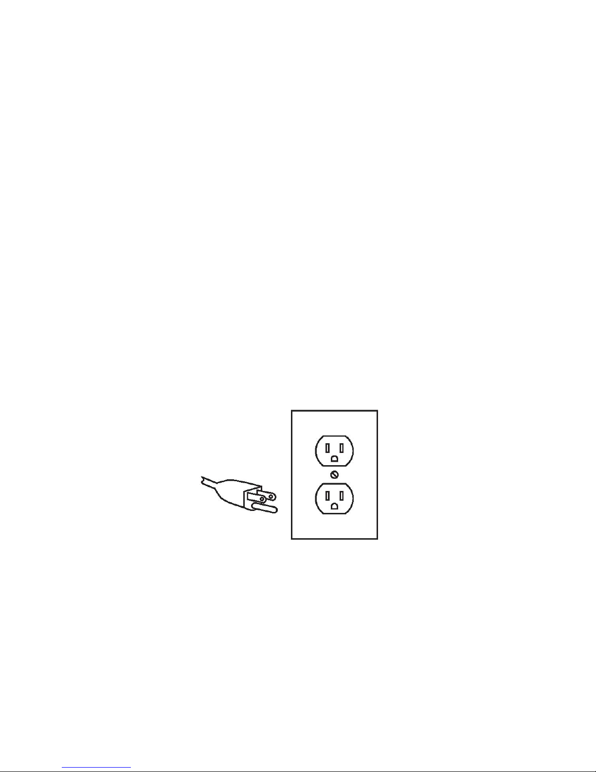
This product is for use on a nominal 120 V circuit and has a grounding plug similar to
the plug illustrated in Table1. Only connect the product to an outlet having the same
conguration as the plug. Do not use an adapter with this product.
3-Prong Plug and Outlet
Any electric powered tool that is marked Ground Required must have tted a three
wired power cord. The main importance of this is the green wire within the cord,
this green wire must at all times be connected to the grounding prong of the plug.
This prong must never be removed or discarded. The green wire Must NEVER be
connected to any other prong. The Three prong plug must only be connected to the
power supply through a three prong power outlet.
The Illustration above shows a three prong plug and outlet.

9
Double Insulated Power Tools
Plug and outlet, 2 prong
Outlets for 2-Prong Plug
Any electric powered tool that is marked Double insulated only need a two prong
connection and will be perfectly safe to operate.
These tools do not require grounding as they are tted with an additional insulation
system internally that complies with all relevant electrical safety standards.
Unlike the three prong tools these tools CAN be connected through outlets suitable for
two prong or three prong plugs.
The Illustration above shows the outlets that this type of tool can be connected to.
Power Extension Cords
Any power tool marked ‘Grounding required’ MUST only be connected to a three wire
extension cord. Only double insulated tools can be connected to two wire cords.
When using any extension cord the machine will suffer a power reduction due to
the drop in voltage caused by the length of the cord. This can be partially offset by
selecting extension cords with lower gauge wire.
MINIMUM GAUGE FOR CORD SETS
Total Length of Cord in Feet(Meter)
0-25 26-50 51-100 101-150
(0-7.6) (7.9-15.2) (15.5-30.5) (30.8-45.7)
Ampere Rating
AWG
4161618160
18 16 14 12
16 16 14 12
14 12 Not Recommended
6 10
10 12
12 16
More Not More
Than Than
Table 1
e.g. Cords marked 14 gauge can carry a higher current than cords marked 16 gauge
therefore when linking extension cords make sure each cords wire gauge matches.

10
Note: Outdoor extension cords used in must carry the letters “W-A” (USA) or “W”
(Canada)
Check all extension cords for damage before use.
Avoid sharp objects.
Do not position the cord where it could be subject to trafc passing over it.
Symbols
IMPORTANT: Some of the following symbols may be used on your tool.
V…………………………volts
A…………………………amperes
Hz………………………..hertz
~…………………….…...alternating current
…/m……………….........revolutions per minute
..................................class II construction (double insulated)
Kg………………………..kilograms
n0………………………...No load speed
..........Conforms to relevant safety standards
DC ………………..…Direct Current
Unpacking
Carefully remove the product and any accessories from the box. Make sure that all
items listed in the packing list are included.
Package contents
A) Drill press
B) Base
C) Column
D) Table
E) Handles
F) User manual
Functional Description
WARNING:Disconnect the plug from the power source before making any assembly,
adjustments or changing accessories. Such preventive safety measures reduce the
risk of starting the tool accidentally.
Assembly
Installing column to base
1. Bolt the column assembly to the base with the three hex screws provided. (Fig.1)
NOTE: Ideally, the base with column attached, should be rmly bolted to a
workbench, prior to the assembly of other components.

11
Installing the work table
1. Thread the Table Locking Handle into the Table Clamp, and leave it loose at this
stage.
2. Slide the Table Clamp with Table over the Column put at desired height and tighten
locking handle. (Fig.2)
Installing the drill press head
1. With assistance, raise the Head, and locate it on top of the Column, ensuring it
slides home fully (Fig.4).
2. Align the head with the base, and rmly secure to the Column with the hex socket
Head Screws.
3. Tighten the two head locking screws with the Allen wrench provided.
Installing handles
Screw the three feed handles rmly into the hub of the feed shaft. (Fig.7)
Installing the drill chuck
1. Slide the work table up the column to within 6" of the spindle.
2. Open the jaws of the chuck to their maximum, using the chuck key supplied.
3. Put a piece of scrap wood on to the table to protect the chuck nose.
4. Ensuring all parts are thoroughly clean, dry, and burr free, place the chuck over
the end of the spindle and pull the spindle down using the feed handles, pressing
the chuck hard against the piece of scrap wood until the chuck is forced home.
Replacing drill bits
1. Use the chuck key provided to loosen the drill chuck.
2. Insert drill bit into chuck all the way up into chuck.
3. Depending on the drill size bring the drill bit out until the whole ute is showing.
4. Tighten by hand until drill bit is centered in chuck.
5. Once centered use chuck key to tighten drill bit.
6. Tighten all three jaws to ensure drill bit is tight so the bit doesn’t slip while drilling.
7. REMOVE chuck key before turning on the drill press.
Mounting the drill press
For your own safety and others around you this drill press should be secured to a
stable work bench, to secure:
1. Place the drill press on the workbench.
2. Secure the drill press onto the workbench using two carriage bolts, at washers, and
nuts through the holes in the base. (hardware not included).
Height adjustment
1. Raise or lower the work table by loosening the table clamp, re-tighten, once at
desired position and height. The work table can also be rotated up to 360 degrees.
(Fig.3)

12
Tilting the work table
1. The worktable can be tilted left or right by loosening the pivot bolt.
2. When returning the table to the level position, line up the register mark with the tilt
scale.
Changing spindle speeds
1. Switch machine off and unplug it.
2. Open the pulley cover. (Fig.6)
3. Undo the Belt Tension Locking Knob (Fig.8) to relieve any tension on the belt, and
referring to the chart, install the belt in the position corresponding to the spindle
speed required.
4. Lever the motor, on its bracket, away from the head, so that tension is applied to the
belt. Tension is correct, when the belt deects by approx. ½” at its centre, when
using reasonable thumb pressure. Lock the motor in this position using the Locking
Knob.
Diag.1
Note:
Tighten the belt only so far that the slippage is eliminated.
A too tight belt will deform during a longer period of rest, which reduces the power of
the motor.
Spindle stop
Your drill press is equipped with a depth stop for drilling multiple holes to a specic
depth.
1. Put drill bit in chuck.
2. Lower the chuck with the power OFF, until the drill contacts the surface of the
work piece, and hold in that position.
3. Turn the stopper nut ring (Fig.5) until the pointer is aligned with the desired depth of

13
the hole required. Tighten the lock nut and lock it.
4. Drill a test hole and make any necessary adjustments.
Secure the tool to a supporting structure before use.
Insert the drill into the jaws of the chuck, ensuring that the jaws do not touch the utes
of the drill. Before tightening the chuck, ensure that the drill is centered within the jaws.
Make sure the table height and position is set so that the drill travel range is sufcient
for the material to be drilled.
Make sure the work is securely clamped. That it is held in a drill vice or bolted to the
table. Never hold the material with your bare hands while drilling. Severe personal
injury can result if the material is ung out of the operator’s hand.
IF THE MATERIAL IS IRREGULARLY SHAPED and cannot be laid at on the table, it
should be securely blocked and clamped. Any tilting, twisting or shifting will result not
only in a roughly drilled hole but also increases the chances of damage to the drill and
personal injury.
FOR SMALL MATERIALS that cannot be clamped to the table, use a drill press vise.
Make sure the vise is clamped or bolted to the table.
WHEN DRILLING COMPLETELY THROUGH WOOD, always position a piece of scrap
wood between the material and the table to prevent splintering on the underside of the
material as the drill breaks through. The scrap piece of wood must be clamped. Also,
set the depth of the drill so that the drill will not come in contact with the table or align
the table so that the hole in its center is in line with the drill bit.
Note: The motor housing may get hot under normal operating conditions
Cutting Speeds
Factors which determine the best speed to use in the drill press operation are:
Type of material to be drilled.
Size of hole.
Type of drill bit.
Finish of the hole desired.
On-Off Switch
Ensure that the switch is in the “OFF” position. If the plug is connected to a receptacle
while the switch is in the “ON” position, the power tool will start operating immediately
and can cause serious injury.
Operation
Always wear eye protection when using this or any other drill press.
Turn on the drill press and wait until it reaches full speed before you start drilling. Use a
clamp or vise to keep the work piece steady. Keep a steady even pressure on the work
piece to avoid burning or dulling of the drill bit. Do not push too hard because this may
overheat the motor and prematurely wear out the drill, work slowly. Obtain a tray with
water and place it next to the drill press to dip your work and keep from overheating or
burning as this will weaken the metal.

14
WARNING: For your own safety, make sure switch is OFF and unplugged from the
power source before doing any maintenance or adjustments. Replace the power cord
immediately if it is cut, worn, or damaged in any way.
WARNING: The use of any other accessories is not recommended because it may
result in serious injury.
Never touch the drill bit while spindle is turning.
Select proper spindle speed and bit for job.
Always remember to remove chuck key before starting.
DANGER: Do not use any drill larger than the stated capacity of the drill press.
Maintenance
WARNING: For your own safety, make sure switch is off and unplugged from the
power source before doing any maintenance or adjustments. Replace the power cord
immediately if it is cut, worn, or damaged in any way.
CLEANING: Regularly clean the work surface with dry brush or clean a cloth. Keep
machined parts of the drill press lightly greased. Always keep the motor and drill chuck
clean.
Prevent metal, wood, dust or other debris from accumulating in this area. If jaws do not
operate smoothly, have the chuck serviced by a qualied technician.
LUBRICATION: For average use, lubricate twice a year with a 20-30 weight household
oil. Lubricate more frequently with increased usage.
POWERCORD: Inspect the power cord periodically and, if damaged, have it repaired
by an authorized technician.
REPLACEMENT PARTS: Replace belts at the rst sign of slippage or fraying. When
servicing, use only identical replacement parts. Use of any other parts will void the
warranty.
STORAGE: Always remove and store drill bits
Accessories
CAUTION: Use only accessories or attachments recommended for use with your
Terratek tool specied in this manual. The use of any other accessories or attachments
might present a risk of injury to persons. Only use accessory or attachment for its
stated purpose.
General Maintenance
1. Keep the air vents free from obstruction and clean regularly
2. Check regularly for any dust particles entering the grills around the motor and the
trigger switch. Use a soft brush to remove any dust particles. Wear safety glasses
to protect your eyes whilst cleaning.
3. Monitor the dust bag (IF EQUIPPED) and empty when approximately half full.
Always empty into an appropriate container. REMEMBER: dust can be hot and
cause re.
4. If the Blade has become dull, replace it. Dull blades will cause increased tear-out

15
and ragged edges on the cuts.
5. Lubricate all moving parts at regular intervals
6. To clean the body of the power tool, only use a soft damp cloth. Do NOT immerse in
water. A mild detergent can be used but NOT petrol or any alcohol based product.
7. Should the power cord become damaged only allow a fully qualied electrician to
replace or repair
Please read the following carefully
ACL Group Ltd. and/or its distributor has provided the parts list and assembly
diagram as a reference tool only. Neither ACL Group Ltd. or its distributor makes any
representation or warranty of any kind to the buyer that he or she is qualied to do any
repairs or replace any parts of this product. ACL Group Ltd. and its distributor expressly
state that all repairs or parts replacement should be done by certied or licensed
technicians. The buyer assumes all risk and liability arising out of his or her repairs or
parts replacement to the original product.
LIMITED WARRANTY
This product is covered by a two year warranty from the date of purchase. If the
product is defective in workmanship or material and upon returning the product to its
distributor/dealer in its original packaging, the distributor will repair and/or replace it
free of charge. This warranty DOES NOT COVER normal wear, or any damage as a
result of accidents, misuse, abuse or negligence. ACL Group Ltd. obligations under this
warranty shall be limited to the repair and/or replacement of the product. ACL Group
Ltd. is not responsible for direct, indirect, or incidental damages. This warranty is void if
the product or any of its components are modied, altered, or in any way changed, or if
the product is used in a manner or with parts that are not recommended by ACL Group
Ltd. To receive a replacement power tool or requested warranty service, you must
present proof of purchase and return all original equipment packaged with the original
product. The replacement power tool will be covered by the limited warranty for the
balance of the two year period from the date of the original purchase. This warranty
applies only to the original purchaser and cannot be transferred.

16
Contenu
Liste des pièces
Fiche technique
Consignes de sécurité
Assemblage
Utilisation de outil
Entretien
Guarantie
Liste des pièces
1 Socie 32 Rondelle
2 Colonne d'appui 33 Panneau d'interrupteur
3 Rondelle 34 Écrou
4 Rondelle élastique 35 Couvert de ressort
5 Boulon 36 Capuchon de ressorte
6 Colonne 37 Index
7 Vis 38 Circuits légers
8 Écrou 39 Siège de l'indicateur
9 Vis hexagonale (Allen) 40 Écrou
10 Blocage de bouton 41 Transformateur
11 Engranage l'unité 42 Voyant DEL
12 Barre de poignée 43 Mangue de serrez
13 Bouton 44 Socie
14 Ressort 45 Rivet
15 Barre coulissante 46 Étiquette d'angle
16 Coussin de l'amortisseur 47 Table de travail
17 Coussin de gomme 48 Boulon
18 Vis 49 Vis
19 Rondelle 50 Mandrin
20 Boulon 51 Arbre
21 Poulie du moteur 52 Roulement à bille
22 Vis 53 Douille d'axe de rotation
23 Courroie-V 54 Ensemble de gomme

17
24 Bouton 55 Anneau de retenue
25 Poulie couvrir 56 Anneau de retenue
26 Verre de l'oeil 57 Douille d'axe de rotation
27 Câble de courant 58 Roulement à bille
28 Inverseur 59 Anneau de retenue
29 Petit interrupteur 60 Poulie de broche
30 Compensation 61 Bâti
31 Vis 62 Moteur
Table of contents
Languages:
Other Terratek Power Tools manuals


