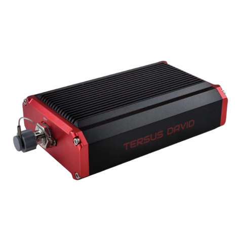
TERSUS David User manual

User Manual
Version V1.0-20180525
Sales & Technical Support:
sales@tersus-gnss.com & support@tersus-gnss.com
More details, please visit www.tersus-gnss.com
User Manual
For David GNSS Receiver
©2018 Tersus GNSS Inc. All rights reserved.

1/ 76
Table of Content
1. Overview....................................................................................................................8
1.1 Introduction ............................................................................................................... 8
1.2 Receiver Features....................................................................................................... 8
1.3 Brief Introduction of GNSS and RTK........................................................................... 9
2. Devices in David Package................................................................................... 11
2.1 Rove Kit Mobile Mode................................................................................................... 12
2.1.1 David Receiver............................................................................................... 14
2.1.2 GNSS Antenna............................................................................................... 14
2.1.3 The 2pin-USB Power Cable......................................................................... 15
2.1.4 COMM1-bluetooth Module ........................................................................... 16
2.1.5 Bracket for Rover........................................................................................... 16
2.1.6 GNSS Antenna Connector........................................................................... 17
2.1.7 COMM2-7pin-USB & DB9 Data Cable....................................................... 17
2.1.8 Other accessories.......................................................................................... 18
2.2 Rover Kit with 1W Radio Station.............................................................................. 20
2.2.1 RS900C 1W/915MHz Radio ........................................................................ 22
2.3 Rover Kit with 2W Radio Station.............................................................................. 22
2.3.1 RS400L2 2W/460MHz Radio....................................................................... 24
2.3.2 COMM2-7pin-USB & 5pin Cable................................................................. 26
2.4 Base Kit Mobile Mode.............................................................................................. 26
2.4.1 Bracket for Base............................................................................................. 28
2.4.2 Tape Meter...................................................................................................... 28
2.5 Base Kit with 1W Radio Station................................................................................ 29
2.6 Base Kit with 2W Radio Station................................................................................ 30
2.7 Base Kit with 30W Radio Station.............................................................................. 31
2.7.1 30W Radio ...................................................................................................... 33
2.7.2 Other cables ................................................................................................... 34
3. General operation.................................................................................................. 36
3.1 Install the GNSS antenna............................................................................................... 36
3.2 Power on David ............................................................................................................. 36

2/ 76
3.3 Communication between Android phone and David.................................................... 37
3.3.1 With Wires....................................................................................................... 38
3.3.2 With an External Bluetooth........................................................................... 40
3.4 FW Upgrade & Auth code.............................................................................................. 41
3.4.1 Firmware Updates .............................................................................................. 42
3.4.2 Auth Code............................................................................................................ 45
3.5 Download Files from Internal eMMC Card.................................................................... 46
3.6 Input command directly to the GNSS board............................................................ 49
4. Introduction of Nuwa®........................................................................................... 51
5. Specification........................................................................................................... 53
5.1 David Receiver............................................................................................................... 53
5.2 ANTENNA AX3702 (HG)................................................................................................. 56
5.3 1W Radio RS900C .......................................................................................................... 57
5.4 2W Radio RS400L2......................................................................................................... 59
5.5 30W Radio RS400L30..................................................................................................... 61
6. Typical operating...................................................................................................... 64
6.1 David as a Rover to receive corrections from Internet............................................ 64
6.2 David as a Base to transmit corrections to Internet ................................................ 67
6.3 Radios Transmit RTK Corrections between Two Davids .......................................... 70
6.4 Data Collection for Post Processing ......................................................................... 72
7. Terminology ............................................................................................................. 75

3/ 76
List of Figures
Figure 1 Outlook of David GNSS receiver..........................................................................8
Figure 2 Outline of David System........................................................................................9
Figure 3 Corrections transmitted via Internet...................................................................10
Figure 4 Corrections transmitted with radios....................................................................10
Figure 5 David in the box....................................................................................................11
Figure 6 Field photo 1 - 1....................................................................................................12
Figure 7 Field photo 1 - 2....................................................................................................13
Figure 8 David Receiver......................................................................................................14
Figure 9 AX3702 (HG) antenna..........................................................................................15
Figure 10 RF cable...............................................................................................................15
Figure 11 2pin-USB Power Cable......................................................................................16
Figure 12 Bluetooth Module................................................................................................16
Figure 13 Bracket for Rover................................................................................................17
Figure 14 GNSS Antenna Connector................................................................................17
Figure 15 COMM2-7pin-USB & DB9 Data Cable............................................................18
Figure 16 USB TypeA Male to DB9 Male cable..............................................................18
Figure 17 USB TypeA Male to USB TypeA Male cable.................................................19
Figure 18 USB TypeA Female to USB (Micro + Type C) OTG cable ..........................19
Figure 19 Height MeasureAccessory...............................................................................19
Figure 20 Battery Bank........................................................................................................20
Figure 21 Field Photo 2 - 1 .................................................................................................20
Figure 22 Field Photo 2-2....................................................................................................21
Figure 23 RS900C 1W Radio Station ...............................................................................22
Figure 24 Field Photo 3 - 1 .................................................................................................23
Figure 25 Field Photo 3 - 2 .................................................................................................23
Figure 26 2W /460MHz Radio............................................................................................25
Figure 27 COMM2-7pin-USB & 5pin Cable......................................................................26
Figure 28 Field Photo 4.......................................................................................................27
Figure 29 Bracket for Base.................................................................................................28
Figure 30 Tape Meter...........................................................................................................29
Figure 31 Field Photo 5.......................................................................................................29
Figure 32 Field Photo 7 - 1 .................................................................................................31
Figure 33 Field Photo 7 - 2 .................................................................................................32
Figure 34 30W Radio Station.............................................................................................33
Figure 35 Power cable for 30W radio................................................................................34
Figure 36 COMM cable for 30W radio ..............................................................................35
Figure 37 David GNSS receiver installation hook...........................................................35
Figure 38 Outline of Android phone to David with Wires ...............................................38
Figure 39 Outline of Android phone to David with Bluetooth.........................................40
Figure 40 Outline of David connected to a Computer ....................................................41
Figure 41 Download file from eMMC card........................................................................46
Figure 42 Booting up page..................................................................................................51
Figure 43 Four Main Windows of Nuwa............................................................................52

4/ 76
Figure 44 Panel of David.....................................................................................................54
Figure 45 Pin Definition of the COMM1/COMM2/DC ports ...........................................55
Figure 46 Outline of Android phone to David with Wire .................................................65
Figure 47 Outline of Android phone to David with Wire .................................................67
Figure 48 Outline of Base/Rover with Radios..................................................................70
Figure 49 Outline of Static Data Collection ......................................................................73

5/ 76
List of Tables
Table 1 The document / software used in this user manual.............................................6
Table 2 Seven David Variants.............................................................................................11
Table 3 Devices in rover mobile mode..............................................................................13
Table 4 Definition of LEDs...................................................................................................14
Table 5 Functions of COMM2-7pin-USB & DB9 Data Cable.........................................18
Table 6 Rover Kit with 1W Radio Station..........................................................................21
Table 7 LED Definition.........................................................................................................22
Table 8 Rover Kit with 2W Radio Station..........................................................................24
Table 9 Button Manual.........................................................................................................25
Table 10 LED Definition.......................................................................................................26
Table 11 Base Kit Mobile Mode..........................................................................................27
Table 12 Base Kit with 1W Radio Station.........................................................................30
Table 13 Base Kit with 30W Radio Station.......................................................................32
Table 14 The Definition of the Control Buttons................................................................33
Table 15 Definition of LEDs ................................................................................................34
Table 16 Detailed steps.......................................................................................................39
Table 17 Detailed steps.......................................................................................................40
Table 18 Preparation for FW update .................................................................................42
Table 19 Detailed Steps for FW update............................................................................43
Table 20 Detailed Steps to download files from eMMC card.........................................46
Table 21 Input commands to the BX306 directly.............................................................49
Table 22 David GNSS Performance..................................................................................53
Table 23 Pin Definition ........................................................................................................55
Table 24 Antenna AX3702 (HG).........................................................................................56
Table 25 Specification for RS900C....................................................................................57
Table 26 Specification for RS400L2..................................................................................59
Table 27 RS400L30 Radio Specification..........................................................................61
Table 28 Detailed steps for rover receive corrections from Internet.............................65
Table 29 Detailed steps for Base transmit corrections to Internet ................................68
Table 30 Detailed steps for David with Radios ................................................................70
Table 31 Detailed Steps for Static Data Collection..........................................................73
Table 32 List of terminology................................................................................................75

6/ 76
Notices
The following notices apply to DAVID receiver.
Changes or modifications to this equipment not expressly approved by
Tersus could void the user‟s authority to operate this equipment or
even has risk to damage the DAVID.
Conventions
The following conventions are used in this manual:
!
Information that supplements or clarifies text.
A caution that actions, operation or configuration may lead to incorrect
or improper use of the hardware.
NUWA is Tersus survey app, four tabs (Project, Device, Survey and Tools) are
provided in the Nuwa® main window. So, in chapter 0, all the operations in the
Survey software will start from these four tabs.
In all the figures, a line with two arrows at the two sides means it‟s a cable. A
line with one arrow gives the installation direction.
Table 1 The document / software used in this user manual
Name
Description
Link
Log & Command
document
Document giving all the
loggings output from David
and all the commands to
David
https://www.tersus-gnss.com/ass
ets/upload/file/20180420120508
17.pdf
Tersus GNSS
Center
Graphical tool to
communicate with David
https://www.tersus-gnss.com/ass
ets/upload/file/20180418153351
742.zip
Nuwa
Survey application running
in the Android platform,
David can be configured
with Nuwa.
Tersus Geomatics
Office
Post processing tool for
static data
https://www.tersus-gnss.com/ass
ets/upload/file/20180418153011
5.rar
A warning that actions, operation or configuration may result in
regulatory noncompliance, safety issues or equipment damage.

7/ 76
Support
If you have a problem and cannot find the information you need in the product
documentation, request technical support using the Tersus website at
www.tersus-gnss.com, or mail to [email protected]

8/ 76
1. Overview
1.1Introduction
Tersus DAVID is a cost-efficient, palm-sized GNSS receiver, mainly for the
mass survey market, but also for UAV/AGV/Agriculture application.
Nuwa, a surveyApp on Android system, is working with David, which can
communicate with an Android platform such as a phone or tablet via USB
cable or an external Bluetooth module. The David can work as a base or a
rover, it can support real-time RTK positioning as well as saving data for PPK
application. Up to 4GB on-board EMMC card makes it easy to save data for
PPK.
The RS-232 serial port, IP67 standard and the external Bluetooth module can
remove most of the inconvenience for field workers. All the operating can be
done in the App Nuwa except downloading raw measurement data file, which
will be done with Tersus GNSS Center, see Table 1 and section 3.5 Download
Files from Internal eMMC Card for detail.
Figure 1 Outlook of David GNSS receiver
1.2Receiver Features
Supports GPS L1/L2, BDS B1/B2 and GLONASS G1/G2.
Support RTCM2.3/3.x, CMR, CMR+ corrections.

9/ 76
Easy to connect an external powerful radio for longer range.
Solution rate can be 5Hz.
20Hz raw measurements output for post processing.
The accuracy of carrier phase can be 1mm.
On-board 4GB eMMC card for data collection
Static post-processing for mm-level accuracy.
Bluetooth module makes wireless connection.
Input power range is 5 - 12V, connect to battery bank directly.
IP67 for water & dust proof, work reliably in harsh condition
The Lemo connectors support mis-installation avoidance.
1.3Brief Introduction of GNSS and RTK
Tersus BX306 GNSS receiver is integrated in David, the board is receiving the
GNSS signals from satellites and RTK corrections from the base, and is
outputting cm-level position, velocity and time. Figure 2 shows David system;
see https://www.tersus-gnss.com/product/bx306-oem-board for more about
BX306 receiver.
Figure 2 Outline of David System

10 / 76
The RTK corrections are transmitted from a base, which can be a CORS
station or a David receiver. The RTK corrections can be transmitted to the
rover via Internet or with external radios.
Figure 3 Corrections transmitted via Internet
Figure 4 Corrections transmitted with radios
If RTK corrections are transmitted via Internet, an Android phone will be
included in the RTK system to transmit/receive the RTK corrections, see
section 6.1 and section 6.2 for detailed operating.

11 / 76
2. Devices in David Package
This chapter will give detailed introduction about all the devices in the
package.
David has seven variants, which are convenient for customers to select per
their application. Different accessories are included in each variant. Table 2
gives a brief description of the seven variants. For more about them, refer to
section 2.1 to section 2.7.
All the seven variants are shipped in a plastic box in Figure 5.
Figure 5 David in the box
Table 2 Seven David Variants
David variants
Description
Rover Kit Mobile
Mode
The David receiver will receive RTK corrections from a
NTRIP caster or a TCP server.
Rover Kit with 1W
Radio Station
The David receiver will receive RTK corrections from an
external 1W 915Mhz radios.
Rover Kit with 2W
Radio Station
The David receiver will receive RTK corrections from an
external 2W 460MHz radios.
Base Kit Mobile
Mode
The David receiver will output RTK corrections to a
NTRIP caster or a TCP server.
Base Kit with 1W
Radio Station
The David receiver will output RTK corrections to an
external 1W 915Mhz radio.

12 / 76
Base Kit with 2W
Radio Station
The David receiver will output RTK corrections to an
external 2W 460MHz radio.
Base Kit with 30W
Radio Station
The David receiver will output RTK corrections to an
external 30W 460MHz radio.
!
1. Rover Kit Mobile Mode and Base Kit Mobile Mode can work
independently.
2. Rover Kit with 1W Radio Station must work with Base Kit with 1W
Radio Station.
3. Rover Kit with 2W Radio Station must work with Base Kit with 2W
Radio Station or Base Kit with 30W Radio Station.
2.1 Rove Kit Mobile Mode
In this variant, the David will be connected to an Android phone with Bluetooth
module or with cables. Tersus Survey Nuwa®App will run in theAndroid phone
to receive RTK corrections from a NTRIP caster or a TCP server.
Refer to section 6.1 for detailed operation.
Figure 6 Field photo 1 - 1
1
2
3

13 / 76
Figure 7 Field photo 1 - 2
Table 3 Devices in rover mobile mode
Devices
Number
Items in the field photos
David GNSS receiver
1
5
GNSS antenna
1
1
GNSS antenna connector
1
Not in the field photo, refer
to section 2.1.6 for detail.
GNSS antenna cable
1
3
2pin-USB power cable
1
8
COMM1-bluetooth module
1
6, refer to 2.1.4
COMM2-7pin-USB & DB9 Data cable
1
Not in the field photo, refer
to section 2.1.7
USB Type A Male to USB Type A
Male cable
1
Not in the field photo, refer
to Figure 17
USB Type A Female to USB(Micro +
Type C) OTG cable
1
Not in the field photo, refer
to Figure 18
USB Type A Male to DB9 Male cable
1
Not in the field photo, refer
to Figure 16
Ranging pole
1
2
Height measure accessory
1
Not in the field photo, See
Figure 19.
Bracket for rover
1
4, see section 2.1.5
Battery bank
1
7, see Figure 20 and 3.2
Power on David
5
4
6
7
8

14 / 76
2.1.1 David Receiver
David has four interfaces, see Figure 8 David Receiver.
Figure 8 David Receiver
David‟s DC is for power input, COMM1 port is for COM1 and CAN ports, and
COMM2 port is for COM2 and USB ports, see chapter 5 for detail.
Table 4 Definition of LEDs
LED
Colour
Description
PWR
RED
ON: the David is power on.
PV
GREEN
ON: David in RTK solution.
Blink: David in Float solution
OFF: David in other position types.
Please see section 3.2 Power on David for more about the booting up
procedure.
Refer to Chapter 5 for the specification of David receiver and the detailed
definition of COMM1, COMM2 and DC ports.
2.1.2 GNSS Antenna
GNSS antenna is used to receive the RF signal from the satellites. AX3702
(HG) is provided in the package, which must be connected to the David with
the RF cable in the package.
Antenna input
DC port
COMM1 port
COMM2 port

15 / 76
Figure 9 AX3702 (HG) antenna
If an antenna from other companies will be used, contact Tersus to get
permission, or the David may not work as it‟s expected.
Figure 10 RF cable
2.1.3 The 2pin-USB Power Cable
The power cable is used to connect a battery bank to the DC port of David.

16 / 76
Figure 11 2pin-USB Power Cable
2.1.4 COMM1-bluetooth Module
This Bluetooth module will use the COM1 port of David.
Figure 12 Bluetooth Module
The Bluetooth can only be installed to the COMM1 port of David.
The SSID for this Bluetooth module is BT420A-xxxxx, where xxxxx is the last 5
digits of the Bluetooth serial number, which is printed on the Bluetooth module.
No password is needed to pair with it.
2.1.5 Bracket for Rover
Bracket for rover is used to fix all the devices on the ranging pole, which bring
much convenience to field staffs.

17 / 76
Figure 13 Bracket for Rover
2.1.6 GNSS Antenna Connector
The GNSS antenna connector is used to install the GNSS antenna or the 30W
radio station antenna to a tripod.
Figure 14 GNSS Antenna Connector
2.1.7 COMM2-7pin-USB & DB9 Data Cable
The COMM2-7pin-USB & DB9 Data Cable has three functions:

18 / 76
Table 5 Functions of COMM2-7pin-USB & DB9 Data Cable
1. Connect to an external 1W radio module.
2. Connect to USB Type A Male to DB9 Male cable (see Figure 16) to
download file saved on the internal eMMC card, refer to section 3.5
Download Files from Internal eMMC Card;
3. Connect to USB Type A Male to USB Type A Male cable (see Figure 17)
and USB Type A Female to USB (Micro +Type C) OTG cable (see Figure
18) to connect the Android phone with David, refer to section 3.3.1.
Figure 15 COMM2-7pin-USB & DB9 Data Cable
2.1.8 Other accessories
USB Type A Male to DB9 Male cable, USB Type A Male to USB Type A Male
cable, USB Type A Female to USB (Micro + Type C) OTG cable and Height
Measure Accessory are included in this variant.
Figure 16 USB Type A Male to DB9 Male cable
The driver for the cable above can be downloaded
!
The COMM2-7pin-USB cable can only be installed into the COMM2 port
of David.

19 / 76
https://www.ugreen.com/drivers/list-USB_To_RS232_Driver-en.html
Figure 17 USB Type A Male to USB Type A Male cable
Figure 18 USB Type A Female to USB (Micro + Type C) OTG cable
The height measure accessory is used to determine the height of the antenna
with higher accuracy.
Figure 19 Height Measure Accessory
A battery bank is used to power on the David, it‟s not included in the package,
and has to be provided by the customers, see section 3.2 Power on David for
Other manuals for David
3
Table of contents
Other TERSUS Receiver manuals

TERSUS
TERSUS Oscar GNSS User manual
TERSUS
TERSUS Oscars User manual
TERSUS
TERSUS David User manual
TERSUS
TERSUS Oscar User manual
TERSUS
TERSUS GeoBee30 User manual

TERSUS
TERSUS Oscar User manual
TERSUS
TERSUS Oscar Ultimate User manual

TERSUS
TERSUS BX316 User manual

TERSUS
TERSUS Oscar Quick start guide

TERSUS
TERSUS NeoRTK User manual
