TERSUS GeoBee30 User manual

User Manual
Version V2.0-20210722
User Manual
For Tersus GeoBee30
Cost-effective Solution for CORS
©2021 Tersus GNSS Inc. All rights reserved.
Sales Enquiry: sales@tersus-gnss.com
More details, please visit www.tersus-gnss.com

User Manual for Tersus GeoBee30 v1.0
2
Revision History
Version
Revision Date
Change Summary
1.0
20210113
Initial Release
2.0
20210722
Add section 5

User Manual for Tersus GeoBee30 v1.0
3
Table of Content
Revision History....................................................................................................................... 2
Table of Content.......................................................................................................................3
List of Figures........................................................................................................................... 5
List of Tables.............................................................................................................................7
1. Introduction...........................................................................................................................8
1.1 Overview......................................................................................................................... 8
1.2 System Structure........................................................................................................... 9
1.3 Devices in GeoBee30 Package................................................................................ 14
1.3.1 David30 GNSS Receiver.................................................................................... 14
1.3.2 AX4E02 GNSS Antenna.....................................................................................15
1.3.3 TR600 Ntrip Modem............................................................................................ 16
1.3.4 Other accessories................................................................................................17
1.4 Installation Guide.........................................................................................................21
1.4.1 Install bottom plate for fixing David30.............................................................. 21
1.4.2 Install bracket and slide rail for TR600.............................................................22
2. General Operation.............................................................................................................23
2.1 Configurations..............................................................................................................23
2.1.1 Accessories Required......................................................................................... 23
2.1.2 Configure David30...............................................................................................23
2.1.3 Configure TR600..................................................................................................27
2.2 Configuration Parameters..........................................................................................33
2.3 Factory Reset...............................................................................................................34
2.4 Firmware Upgrade...................................................................................................... 34
2.5 Observation Data Storage......................................................................................... 36
3. Specifications.....................................................................................................................39
3.1 David30 GNSS Receiver........................................................................................... 39

User Manual for Tersus GeoBee30 v1.0
4
3.2 AX4E02 GNSS Antenna............................................................................................ 42
3.3 TR600 Ntrip Modem................................................................................................... 43
4. Typical Application............................................................................................................ 45
4.1 GeoBee30 working under Ntrip server mode......................................................... 45
4.2 GeoBee30 working under Ntrip client mode...........................................................45
4.3 Check Link Status using Web portal........................................................................ 47
5. Lightning-Proof Design.....................................................................................................48
5.1 Direct lightning protection.......................................................................................... 48
5.2 Inductive lightning protection.....................................................................................49
5.2.1Power lightning protection................................................................................... 49
5.2.2Lightning protection for communication cables................................................49
5.2.3Grounding net........................................................................................................50
6. Terminology........................................................................................................................51

User Manual for Tersus GeoBee30 v1.0
5
List of Figures
Figure 1.1 GeoBee30 System Structure..........................................................9
Figure 1.2 David30 GNSS Receiver.............................................................. 14
Figure 1.3 AX4E02 GNSS Antenna................................................................15
Figure 1.4 TNC-J to TNC-J Cable (GNSS antenna cable, 25m by default)
..................................................................................................................... 15
Figure 1.5 TR600 side view 1......................................................................... 16
Figure 1.6 TR600 side view 2......................................................................... 16
Figure 1.7 COMM1-Bluetooth Module...........................................................17
Figure 1.8 DC-5pin AC Power Adapter with 1.2m cable.............................17
Figure 1.9 COMM2-7pin to TR600-DC-2pin & DB9 female & USB cable18
Figure 1.10 COMM1-7pin to DB9 male Cable..............................................18
Figure 1.11 RS232 to RS485 converter........................................................ 19
Figure 1.12 DB9 female to TR600-RS485-5pin cable................................ 19
Figure 1.13 DB9 Female to USB Type A Male converter cable.................19
Figure 1.14 USB Type A Female to USB (Micro +Type C) OTG cable.... 19
Figure 1.15 4G antenna for TR600................................................................ 20
Figure 1.16 Wi-Fi antenna for TR600............................................................ 20
Figure 1.17 Ethernet cable 1.5m.................................................................... 20
Figure 1.18 Bottom plate for fixing David30..................................................21
Figure 1.19 Dimension of bottom plate..........................................................21
Figure 1.20 TR600 dimension.........................................................................22
Figure 1.21 Bracket for TR600........................................................................22
Figure 1.22 Slide rail for TR600 (20cm)........................................................ 22
Figure 1.23 TR600 with bracket and slide rail.............................................. 22
Figure 2.1 Configure David30 using Nuwa app........................................... 26
Figure 2.2 Properties for Internet Protocol (TCP/IP)................................... 27
Figure 2.3 Set IP address as ‘Obtain an IP address automatically’..........27

User Manual for Tersus GeoBee30 v1.0
6
Figure 2.4 Connect Ethernet cables.............................................................. 28
Figure 2.5 Login TR600 configuration interface...........................................28
Figure 2.6 Check the current connection status.......................................... 29
Figure 2.7 Select network in Network Settings............................................ 29
Figure 2.8 Mobile communication network settings.................................... 30
Figure 2.9 WAN setting.................................................................................... 30
Figure 2.10 WiFi Client setting........................................................................31
Figure 2.11 LAN setting....................................................................................31
Figure 2.12 Set Ntrip info in Ntrip configuration interface...........................32
Figure 2.13 Set Virhub configuration............................................................. 33
Figure 2.14 Factory Reset for TR600............................................................ 34
Figure 2.15 Update firmware for David30..................................................... 35
Figure 2.16 Update firmware for TR600........................................................36
Figure 2.17 Launch STRSVR in RTKLIB...................................................... 37
Figure 2.18 Input NTRIP Client information..................................................37
Figure 2.19 Output information....................................................................... 37
Figure 2.20 Start saving observation data.................................................... 38
Figure 3.1 Panel of David30............................................................................41
Figure 3.2 Pin Definition of the COMM1/COMM2/DC ports.......................41
Figure 4.1 GeoBee30 under Ntrip server mode...........................................45
Figure 4.2 GeoBee30 under Ntrip client mode.............................................46

User Manual for Tersus GeoBee30 v1.0
7
List of Tables
Table 1 Definition of LEDs............................................................................... 14
Table 2 David30 GNSS Performance............................................................ 39
Table 3 Pin Definition of connectors on David30.........................................41
Table 4 AX4E02 GNSS Antenna.....................................................................42
Table 5 Ntrip Modem TR600 specifications.................................................. 43

User Manual for Tersus GeoBee30 v1.0
8
1. Introduction
This chapter mainly introduces the overview, system structure, package list,
and installation guide of the Tersus GeoBee30 which is an upgraded version of
Tersus GeoBee.
1.1 Overview
The Tersus GeoBee30 is a dedicated and cost-effective solution to establish a
permanent reference station. With Tersus Ntrip Caster Service, Ntrip Modem
and David30 Receiver, the GeoBee30 opens the possibility for users to
transmit Real Time Kinematic (RTK) corrections via Internet (Ethernet or
2G/3G/4G) in a simple, user-friendly way, just using a SIM card or Ethernet
cable without any need of a static IP. GeoBee30 can also work as GNSS
Rover to receive RTK corrections from Tersus Ntrip Caster or any CORS
service.
Ntrip server mode: use David30 GNSS receiver to create a base station. This
temporary base or CORS are for surveying, agriculture, UAV, machine control,
and etc. It is also ideal for deformation monitoring. Tersus GNSS Inc. provides
Ntrip Caster to transfer data.
Ntrip client mode: connect David30 or other Tersus GNSS receivers to Tersus
Ntrip Caster or any Ntrip/CORS service. David30 is mainly used for surveying,
and also used as a GNSS sensor in various applications, such as mobile
mapping, UAV, machine control, agriculture, and etc.

User Manual for Tersus GeoBee30 v1.0
9
1.2 System Structure
Set up the GeoBee30 system according to the figure below.
Figure 1.1 GeoBee30 System Structure
No.
Name
1
Antenna (AX4E02 in the figure above, customizable)
2
TNC-J to TNC-J cable (25m by default, customizable)
3
David30 GNSS Receiver
4
Power Adapter (short for ‘DC-5pin AC Power Adapter with 1.2m cable’)
5
COMM1 cable (short for ‘COMM1-7pin to DB9 male cable’)
6
COMM2 cable (short for ‘COMM2-7pin to TR600-DC-2pin & DB9 female & USB cable’)
7
Ntrip Modem TR600
8
4G antenna for TR600
9
Wi-Fi antenna for TR600
10
Ethernet cable 1.5m

User Manual for Tersus GeoBee30 v1.0
10
Note:
1) There are two configuration modes for GeoBee30. GeoBee30 system is zero configuration
if customer adopts GeoCaster provided by Tersus GNSS Inc., as GeoBee30 is
pre-configured when shipped out of factory. GeoBee30 system needs to be configured if
customers demand to set up caster by themselves.
2) David30 GNSS receiver uploads RTCM stream to the NTRIP caster using Ethernet (default) or
Wi-Fi or 2G/3G/4G sorted by priority.
a. When using Ethernet to configure TR600, use Ethernet cable to connect the LAN2 port of
TR600 to your computer, connect LAN1/WAN port to a router to access internet. Make
sure the IP address of your computer is set as “Obtain an IP address automatically”. Type
192.168.100.1 in your browser, use username “root” and “1234” to enter web config page,
make sure the DHCP is on in LAN setting so that TR600 can automatically obtain an IP
address.
b. When using Wi-Fi to configure TR600, search SSID “TR-600” on your computer and
connect it use password 12345678. Type 192.168.100.1 in the browser of your
computer or mobile phone or tablet, use username “root” and “1234” to enter web
config page.
Please note, both Wi-Fi client and Wi-Fi hotspot of Ntrip Modem TR600 are
supported, however they cannot be enabled simultaneously. Wi-Fi hotspot
function is to share internet connection to other devices or configure TR600 via Wi-Fi.
Wi-Fi client function is to use Wi-Fi connection to communicate with caster when
Ethernet connection is not available.
When using Wi-Fi to communicate with caster, choose Wi-Fi Client to access internet
in Network Settings of TR600. Select a SSID to be used and type the Wi-Fi password
in the PSK pin area, click [Save] to save this setting.

User Manual for Tersus GeoBee30 v1.0
11
Figure 1.2 Wi-Fi client setting
c. When using 2G/3G/4G network for data transmission, GeoBee30 will consume no
more than 3GB mobile data per month. Please contact with your local mobile carrier if
there is any restrictions on wap or data usage.
3) Place the antenna (AX4E02 in the Figure 1.1) in the outdoor open environment. Install
Wi-Fi antenna when Wi-Fi connection is for data communication, and set TR600 as Wi-Fi
client. Install 4G antenna when 2G/3G/4G SIM card is used for data communication.
4) GeoBee30 starts to work in auto start mode by default once it is powered up. According to
the autonomous positioning (without RTK or DGPS), it smoothes out the average value to
be the base coordinate. GeoBee30 outputs the RTCM32 corrections data and sends to the
Ntrip server through LAN, WIFI or 2G/3G/4G mobile network.
5) For the known phase center coordinates of the AX4E02 antenna, the two configuration
methods are as follows:
a. Use the COMM1-Bluetooth module in the package, unplug the COMM1 cable and
insert the Bluetooth module to the COMM1 port of David30 GNSS receiver. Launch
Nuwa app on an android device, connect David30 by paring Bluetooth. Create a base
configuration with manual start in radio mode1, fill in the base coordinates, antenna
height and Ntrip network information. Detailed operation refers to User Manual for

User Manual for Tersus GeoBee30 v1.0
12
David30 GNSS Receiver. After completing the configuration, disconnect the Bluetooth
connection, disconnect the Bluetooth module and connect back the COMM1 cable.
Figure 1.3 Configure David30 using Nuwa app
Note1: Use Radio Mode in Nuwa when configuring GeoBee30. Because the external
radio and TR600 are both external data link, the principal is the same (log the data
from David30 to external data link).
b. Use the ‘DB9 Female to USB Type A Male converter cable’ to connect the COMM1
cable in Figure 1.1 and a computer, open Tersus GNSS Center application on the
computer, and type below commands in the command window:
UNLOGALL //remove all logs
UNDULATION USER 0.0 //Set user specified undulation value for ellipsoid height2
FIX POSITION B L H //B: latitude (degree), L: longitude (degree), H: height (m)
For example: FIX POSITION 31.24523012 121.58922341 40.35
or POSAVE ON 0.02 //Turn on position average for 0.02 hour (72s)
LOG COM2 RTCM1006 ONTIME 10 //output the base coordinate
LOG COM2 RTCM1074 ONTIME 1 //output GPS observations
LOG COM2 RTCM1084 ONTIME 1 //output GLONASS observations
LOG COM2 RTCM1094 ONTIME 1 //output Galileo observations
LOG COM2 RTCM1114 ONTIME 1 //output QZSS observations
LOG COM2 RTCM1124 ONTIME 1 //output BeiDou observations
LOG COM2 RTCM1230 ONTIME 10 //output GLONASS bias information
LOG COM2 RTCM1033 ONTIME 10 //output antenna, receiver information
(Below commands output ephemerides, not default configuration)
LOG COM2 RTCM1019 ONTIME 5 //GPS ephemerides
LOG COM2 RTCM1020 ONTIME 5 //GLONASS ephemerides
LOG COM2 RTCM1042 ONTIME 5 //BeiDou ephemerides
LOG COM2 RTCM1044 ONTIME 5 //QZSS ephemerides

User Manual for Tersus GeoBee30 v1.0
13
LOG COM2 RTCM1046 ONTIME 5 //Galileo ephemerides
SAVECONFIG //save configuration
Note2: If customer needs to use global geoidal height model EGM96 for mean sea
level height, type below command to replace the undulation command above.
UNDULATION EGM96 //Set EGM96 geoidal height model
More details about logs and commands refer to BX40C log & Command
document.
Power cycle the receiver or input RESET command to make the above configuration
effective.
6) The known phase center coordinates of the AX4E02 antenna can be obtained from
surveying and mapping department of local government, or calculated from commercial
software such as Bernese or Gamit.
7) If customer needs GeoBee30 work with local CORS system, calculate the accurate
coordinate of the base station under the local CORS framework and configure the base
station with this accurate coordinate. The calculation to obtain this accurate coordinate can
be PPP method and coordinate conversion via point correction using Nuwa app. You can
contact Tersus technical support for detailed method.

User Manual for Tersus GeoBee30 v1.0
14
1.3 Devices in GeoBee30 Package
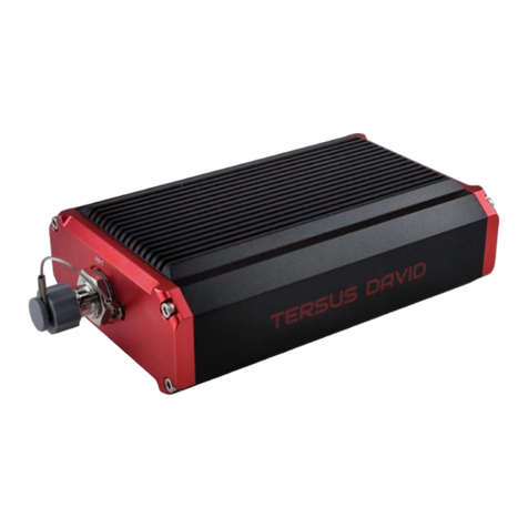
1.3.1 David30 GNSS Receiver
David30 has four interfaces which is shown below.
Figure 1.5 David30 GNSS Receiver
The DC port of David30 is for power input and CAN port, COMM1 port is for
COM1, PPS and Event, and COMM2 port is for COM2 and USB ports, refer to
section 3.1 for detailed specification of David30.
Table 1 Definition of LEDs
LED
Colour
Description
RTK
Red
ON: David30 in Fixed solution.
Blink: David30 in Float and DGPS solution.
OFF: David30 in other position types.
SV
Red
ON: normal state.
Blink: David30 is searching satellites.
PWR
Blue
ON: the David30 is power on.
DC port
COMM1 port
COMM2 port
Antenna

User Manual for Tersus GeoBee30 v1.0
15
1.3.2 AX4E02 GNSS Antenna
AX4E02 GNSS antenna is used to receive the RF signal from the satellites,
and it must be connected to the David30 with the GNSS antenna cable in the
package.
Figure 1.6 AX4E02 GNSS Antenna
If an antenna from other companies is used, contact Tersus to obtain
permission, or the David30 receiver may not work as expected.
Figure 1.7 TNC-J to TNC-J Cable (GNSS antenna cable, 25m by default)

User Manual for Tersus GeoBee30 v1.0
16
1.3.3 TR600 Ntrip Modem
Figure 1.8 TR600 side view 1
Figure 1.9 TR600 side view 2

User Manual for Tersus GeoBee30 v1.0
17
1.3.4 Other accessories
Figure 1.10 COMM1-Bluetooth Module
The Bluetooth can only be installed to the COMM1 port of David30.
This Bluetooth module is used to connect to the COMM1 port of David30
receiver.
The SSID of this Bluetooth module is BT420R-xxxxx_xxxxxx, where the first
xxxxx is the last 5 digits of the Bluetooth serial number, which is printed on the
Bluetooth module. No password is needed to pair with it.
Figure 1.11 DC-5pin AC Power Adapter with 1.2m cable

User Manual for Tersus GeoBee30 v1.0
18
Figure 1.12 COMM2-7pin to TR600-DC-2pin & DB9 female & USB cable
The COMM2-7pin to TR600-DC-2pin & DB9 female & USB cable has two
functions:
1) Connect to the USB port of a computer to download the file saved on the
internal eMMC, refer to section Download Files from Internal eMMC in
David30 user manual;
2) Connect to USB Type A Female to USB (Micro +Type C) OTG cable (refer
to Figure 1.14) to connect the Android phone or controller with David30.
Figure 1.13 COMM1-7pin to DB9 male Cable
!
The circular connector of the COMM2-7pin to TR600-DC-2pin & DB9
female & USB cable can only be installed into the COMM2 port of
David30 GNSS Receiver.
!
The circular connector of the COMM1-7pin to DB9 male cable can only
be installed into the COMM1 port of David30 GNSS Receiver.

User Manual for Tersus GeoBee30 v1.0
19
Figure 1.14 RS232 to RS485 converter
Figure 1.15 DB9 female to TR600-RS485-5pin cable
Figure 1.16 DB9 Female to USB Type A Male converter cable
Figure 1.17 USB Type A Female to USB (Micro +Type C) OTG cable

User Manual for Tersus GeoBee30 v1.0
20
Figure 1.18 4G antenna for TR600
Figure 1.19 Wi-Fi antenna for TR600
Figure 1.20 Ethernet cable 1.5m
Other manuals for GeoBee30
1
Table of contents
Other TERSUS Receiver manuals
TERSUS
TERSUS Oscars User manual
TERSUS
TERSUS Oscar Quick start guide

TERSUS
TERSUS BX316 User manual
TERSUS
TERSUS Oscar User manual

TERSUS
TERSUS Oscar GNSS User manual

TERSUS
TERSUS Oscar User manual
TERSUS
TERSUS Oscar Ultimate User manual
TERSUS
TERSUS David User manual
TERSUS
TERSUS PRECIS-BX316R User manual

TERSUS
TERSUS David User manual

