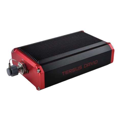
TERSUS BX306 User manual

User Manual
User Manual
Version V2.0-20190314
User Manual
For BX Series GNSS Receiver
©2019 Tersus GNSS Inc. All rights reserved.
Sales & Technical Support:
More details, please visit www.tersus-gnss.com

User Manual for BX Series GNSS Receiver v2.0
I
Revision History
Rev
Description
Date
Owner
1.0
Issued for Review
2018/06/29
CB
2.0
In section 1.2, add OEM board of BX316 and BX316R, add
BX316D enclosure;
In section 1.2.7, remove external SD card for BX316 and
BX316R enclosure;
In chapter 2, update pictures, links, tables and commands;
In section 4, list technical specifications for all BX series
products;
In section 5.1, update rules for the file name;
In section 5.6, change RS05B radio to RS460 radio,
update commands for outputting base position.
2019/03/14
LC

User Manual for BX Series GNSS Receiver v2.0
II
Table of Content
Revision History............................................................................................................I
Table of Content.......................................................................................................... II
List of Figures............................................................................................................. VI
List of Tables.............................................................................................................. IX
Notices.......................................................................................................................... 1
1. Introduction............................................................................................................4
1.1 Overview of BX Series GNSS Receivers..................................................4
1.1.1 BX GNSS OEM Boards........................................................................4
1.1.2 BX GNSS Enclosures...........................................................................4
1.2 Related Documents and Information.........................................................5
1.2.1 OEM BX306 Board................................................................................5
1.2.2 OEM BX306Z Board............................................................................. 7
1.2.3 OEM BX316 Board................................................................................9
1.2.4 OEM BX316R Board...........................................................................11
1.2.5 OEM BX316D Board.......................................................................... 12
1.2.6 BX306 Enclosure................................................................................ 14
1.2.7 BX316 Enclosure................................................................................ 15
1.2.8 BX316R Enclosure..............................................................................17
1.2.9 BX316D Enclosure..............................................................................19
1.3 BX Receivers System Overview.............................................................. 21
1.3.1 BX Series OEM Boards......................................................................22
1.3.2 BX Enclosures..................................................................................... 22

User Manual for BX Series GNSS Receiver v2.0
III
1.3.3 Antenna................................................................................................ 23
1.3.4 Power Supply.......................................................................................23
1.3.5 Communication Equipment............................................................... 23
1.3.6 Internal eMMC Card/External SD Card........................................... 23
1.3.7 Enable Heading...................................................................................24
2. Installation........................................................................................................... 25
2.1 Shipping Box............................................................................................... 25
2.2 UART to USB converter............................................................................ 26
2.3 Selecting a GNSS antenna.......................................................................28
2.4 Power Supply Requirement......................................................................29
2.5 OEM Boards Installation Overview..........................................................30
2.6 Tersus GNSS Center Software................................................................ 31
2.6.1 Auto Base Station List Function........................................................34
2.7 Transmitting and Receiving Corrections.................................................36
2.8 Heading Output...........................................................................................37
3. Firmware Update and Auth Code....................................................................39
3.1 Firmware Update Overview...................................................................... 39
3.2 Firmware Update Using Tersus GNSS Center...................................... 40
3.3 Auth Code....................................................................................................45
4. Technical Specifications....................................................................................46
4.1 BX306 Board...............................................................................................46
4.1.1 BX306 Specifications..........................................................................46
4.1.2 Connectors on BX306 board.............................................................49

User Manual for BX Series GNSS Receiver v2.0
IV
4.1.3 Reference Schematic of the Interface Board..................................50
4.2 BX306Z Board............................................................................................ 52
4.2.1 BX306Z Specifications....................................................................... 52
4.2.2 Connectors on BX306Z board.......................................................... 55
4.3 BX316 Board...............................................................................................59
4.3.1 BX316 Specifications..........................................................................59
4.3.2 40pin external cable............................................................................62
4.4 BX316R Board............................................................................................ 64
4.4.1 BX316R Specifications.......................................................................64
4.4.2 40pin external cable............................................................................65
4.5 BX316D Board............................................................................................ 65
4.5.1 BX316D Specifications.......................................................................65
4.5.2 Connectors on BX316D board.......................................................... 68
4.6 BX306 Enclosure........................................................................................70
4.6.1 BX306 Enclosure Specifications.......................................................70
4.6.2 20pin external cable............................................................................71
4.7 BX316 Enclosure........................................................................................73
4.7.1 BX316 Enclosure Specifications.......................................................73
4.7.2 40pin external cable............................................................................75
4.8 BX316R Enclosure.....................................................................................76
4.8.1 BX316R Enclosure Specifications....................................................76
4.8.2 40pin external cable............................................................................78
4.9 BX316D Enclosure.....................................................................................78

User Manual for BX Series GNSS Receiver v2.0
V
4.9.1 BX316D Enclosure Specifications....................................................78
4.9.2 20pin external cable............................................................................80
5. Typical Application............................................................................................. 81
5.1 Data Collection on Internal eMMC...........................................................81
5.2 Download Files from Internal eMMC.......................................................84
5.3 Connect BX306 to an External Bluetooth...............................................87
5.3.1 Communicate with NTRIP Client App.............................................. 88
5.4 Save Data to an External Data Logger................................................... 91
5.5 Communicate with STRSVR Tool............................................................ 92
5.6 Create RTK using BX306 and a Radio................................................... 95
5.6.1 Radio to Transmit RTK Corrections................................................. 96
5.6.2 Radio to Receive RTK Corrections.................................................. 97
5.7 Connect BX306 to Pixhawk...................................................................... 97
5.8 Uninstall the Cable from BX306 Enclosure..........................................101
6. Terminology...................................................................................................... 102

User Manual for BX Series GNSS Receiver v2.0
VI
List of Figures
Figure 1.1 Overview of BX306 Board...................................................................... 5
Figure 1.2 The other side of BX306 Board..............................................................6
Figure 1.3 Overview of BX306Z Board.................................................................... 7
Figure 1.4 The other side of BX306Z Board........................................................... 8
Figure 1.5 Overview of BX316 Board...................................................................... 9
Figure 1.6 The other side of BX316 Board........................................................... 10
Figure 1.7 Overview of BX316R Board..................................................................11
Figure 1.8 The other side of BX316R Board........................................................ 12
Figure 1.9 Overview of BX316D Board................................................................. 12
Figure 1.10 The other side of BX316D Board...................................................... 13
Figure 1.11 Overview of BX306 Enclosure........................................................... 14
Figure 1.12 BX306 Enclosure Panel......................................................................15
Figure 1.13 Overview of BX316 Enclosure...........................................................15
Figure 1.14 BX316 Enclosure Panel......................................................................16
Figure 1.15 Overview of BX316R Enclosure........................................................ 18
Figure 1.16 Overview of BX316D Enclosure........................................................ 19
Figure 1.17 BX316D Enclosure Panel...................................................................20
Figure 1.18 System Overview of BX Boards........................................................ 21
Figure 2.1 Carrying case..........................................................................................25
Figure 2.2 Major Parts in the BX306 GNSS Kit Package...................................26
Figure 2.3 Major Parts in the BX306 GNSS UAV Kit Package..........................26
Figure 2.4 UART to USB converter........................................................................27
Figure 2.5 Device Manager..................................................................................... 27
Figure 2.6 AX3702 GNSS antenna........................................................................ 28
Figure 2.7 AX3703 mini GNSS antenna................................................................28

User Manual for BX Series GNSS Receiver v2.0
VII
Figure 2.8 AX3705 Helix Antenna.......................................................................... 28
Figure 2.9 Config Page of Tersus GNSS Center................................................. 32
Figure 2.10 BX306 Enclosure Connected to a Laptop....................................... 33
Figure 2.11 Main Windows of Tersus GNSS Center........................................... 33
Figure 2.12 Auto Base Station List interface........................................................ 35
Figure 2.13 Fixed position for base station...........................................................35
Figure 2.14 Base/Rover Configure.........................................................................36
Figure 3.1 Main interface of Tersus GNSS Center.............................................. 40
Figure 3.2 Stop button on Tersus GNSS Center..................................................41
Figure 3.3 Find UpdateFirmware in Tools bar...................................................... 41
Figure 3.4 Select file to update............................................................................... 42
Figure 3.5 Update in progress................................................................................ 42
Figure 3.6 Firmware update successful................................................................ 43
Figure 3.7 Advance setting for firmware update.................................................. 44
Figure 3.8 Advance Update Setting....................................................................... 44
Figure 4.1 Connector J3 on BX306 board............................................................ 49
Figure 4.2 3.3V Reference Schematic...................................................................51
Figure 4.3 5V Reference Schematic......................................................................51
Figure 4.4 Reference Schematic for a Serial Port............................................... 51
Figure 4.5 Reference Schematic for USB.............................................................52
Figure 4.6 Connectors J20 and J21 of BX306Z...................................................55
Figure 4.7 Outline of the 40pin external cable......................................................62
Figure 4.8 Connector J3 of BX316D......................................................................68
Figure 4.9 Outline of the 20pin external cable......................................................72
Figure 5.1 Cable is assembled............................................................................. 101
Figure 5.2 Uninstall the Cable.............................................................................. 101
Figure 5.3 Cable between Pixhawk and BX306...................................................97

User Manual for BX Series GNSS Receiver v2.0
VIII
Figure 5.4 Outline of BX306 connected to Pixhawk............................................97
Figure 5.5 Pixhawk Get Position from BX306...................................................... 98
Figure 5.6 RTK corrections from the base BX306 are received......................100
Figure 5.7 GPS status changes to rtk Fixed.......................................................100
Figure 5.8 Transfer Cable........................................................................................ 95
Figure 5.9 Outline of BX306 Connected to RS460 Radio.................................. 96
Figure 5.10 Data logger DL207.............................................................................. 91
Figure 5.11 Outline of BX306 Connected to DL207............................................ 91
Figure 5.12 BT120 and the Cable.......................................................................... 87
Figure 5.13 Outline of BX306 Connected to BT120............................................87
Figure 5.14 Click Settings in NTRIP Client app................................................... 88
Figure 5.15 Setting page of the NTRIP Client app.............................................. 89
Figure 5.16 Input Bluetooth name in the receiver settings.................................89
Figure 5.17 Reported location of the receiver...................................................... 90
Figure 5.18 Configure serial port COM2............................................................... 93
Figure 5.19 NTRIP Client configuration.................................................................93
Figure 5.20 Draft position of the receiver..............................................................94
Figure 5.21 Input and Output data in progress.................................................... 94
Figure 5.22 Download Files from eMMC Card with a Serial Port......................84
Figure 5.23 Download Files from eMMC Card with an USB Port..................... 84
Figure 5.24 5pin to USB Type A male cable........................................................ 85
Figure 5.25 File download using Tersus Download.............................................85
Figure 5.26 Select serial port for Download Port................................................. 86
Figure 5.27 Select download speed.......................................................................86
Figure 5.28 File downloading in progress............................................................. 86

User Manual for BX Series GNSS Receiver v2.0
IX
List of Tables
Table 0.1 Document / Software used in this User Manual....................................3
Table 1.1 Features of BX306 Board.........................................................................5
Table 1.2 LED Definition of BX306 board................................................................6
Table 1.3 Features of BX306Z Board...................................................................... 7
Table 1.4 LED Definition of BX306Z Board............................................................ 8
Table 1.5 Features of BX316 Board.........................................................................9
Table 1.6 LED Definition of BX316 Board............................................................. 10
Table 1.7 Features of BX316R Board....................................................................11
Table 1.8 Features of BX316D Board.................................................................... 12
Table 1.9 LED Definition of BX316D Board..........................................................13
Table 1.10 Features of BX306 Enclosure..............................................................14
Table 1.11 LED Definition of BX306 Enclosure................................................... 15
Table 1.12 Features of BX316 Enclosure..............................................................16
Table 1.13 LEDs on BX316 Enclosure Panel....................................................... 17
Table 1.14 Features of BX316R Enclosure...........................................................18
Table 1.15 Features of BX316D Enclosure...........................................................19
Table 1.16 LED Definition of BX316D Enclosure................................................ 20
Table 2.1 Input Power Requirements.....................................................................30
Table 2.2 Definition of the lights on Tersus GNSS Center..................................32
Table 4.1 BX306 Board Specifications.................................................................. 46
Table 4.2 Interface Signals Definition.................................................................... 49
Table 4.3 BX306Z Board Specifications................................................................52
Table 4.4 2X12 Header Signals Definition............................................................ 56
Table 4.5 2x3 Header Signals Definition............................................................... 58

User Manual for BX Series GNSS Receiver v2.0
X
Table 4.6 BX316 Board Performance.................................................................... 59
Table 4.7 Pin Definition of the 40pin external cable............................................ 63
Table 4.8 BX306D Board Specifications................................................................65
Table 4.9 Interface Signals Definition.................................................................... 68
Table 4.10 BX306 Enclosure Specifications......................................................... 70
Table 4.11 Pin Definition of the 20pin external cable.......................................... 72
Table 4.12 BX316 Enclosure Specifications......................................................... 73
Table 4.14 BX316R Enclosure Specifications...................................................... 76
Table 4.14 BX316D Enclosure Specifications...................................................... 78

User Manual for BX Series GNSS Receiver v2.0
1
Notices
FCC Notices
The BX306 enclosure has been tested and found to comply with the radiated
and conducted emission limits for a Class A digital device. The Class A limits
are designed to provide reasonable protection against harmful interference in
a residential installation.
The BX316 enclosure has been tested and found to comply with the radiated
and conducted emission limits for a Class A digital device. The Class A limits
are designed to provide reasonable protection against harmful interference in
a residential installation.
CE Marking
Tersus GNSS Inc. declares that BX306 enclosure and BX316 enclosure are in
compliance with the essential requirements (radio performance,
electromagnetic compatibility and electrical safety) and other relevant
provisions of Directive 1999/5/EC, EMC Directive 2004/108/EC, and the RoHS
Recast Directive 2011/65/EU. Therefore the equipment is labeled with the
following CE-marking.
The Declaration of Conformity may be obtained from Tersus GNSS Inc.

User Manual for BX Series GNSS Receiver v2.0
2
The following notices apply to all Tersus BX series receivers.
Changes or modifications to this equipment not expressly approved
by Tersus could void the user’s authority to operate this equipment or
even has risk to damage the receivers.
Conventions
The following conventions are used in this manual:
!
Information that supplements or clarifies text.
A caution that actions, operation or configuration may lead to incorrect
or improper use of the hardware.
Tersus is providing BX series GNSS receivers with OEM version as well as
with enclosure in a metal case. When a board is mentioned, it’s OEM version
of the receiver, specifically. When enclosure is mentioned, it’s receiver version
in a metal case, specifically.
In this manual, all the commands to a receiver are in capital letters, which is
just for easy identification, the commands are not case-sensitive.
A warning that actions, operation or configuration may result in
regulatory noncompliance, safety issues or equipment damage.

User Manual for BX Series GNSS Receiver v2.0
3
Table 0.1 Document / Software used in this User Manual
Name
Description
Link
Log & Command
document
Document providing all the loggings
output from BX series receivers and
all the commands to the receivers
https://www.tersus-gnss.com/document
under GNSS OEM Board / User Manual
Tersus Tool Suite
Tersus Tools including
TersusDownload, TersusGeoPix,
TersusGNSSCenter, TersusUpdate,
TersusRinexConverter
https://www.tersus-gnss.com/software
RTKLIB
A free & popularly used Post
processing tool
http://www.rtklib.com/
Mission Planner
A popular Ground Station software
http://firmware.ardupilot.org/Tools/Mission
Planner/
Support
If there is any problem and the information needed cannot be found in the
product documentation, request technical support using the Tersus website at
www.tersus-gnss.com, or mail to su[email protected]

User Manual for BX Series GNSS Receiver v2.0
4
1. Introduction
1.1 Overview of BX Series GNSS Receivers
BX series GNSS receivers are cost-efficient GNSS RTK board for cm-level
positioning, which can be used for real-time RTK positioning as well as raw
data collection for post-processing application. BX receivers support existed
and planned GPS, BeiDou and GLONASS signals. Both OEM boards and the
enclosures are designed for the flexibility of integration and configuration.
BX series receivers are delivered with OEM boards as well as in enclosures.
For further information about BX receivers, refer to
https://www.tersus-gnss.com/ for more details.
1.1.1 BX GNSS OEM Boards
OEM BX306 board – refer to section 1.2.1 for details;
OEM BX306Z board – refer to section 1.2.2 for details;
OEM BX316 board – refer to section 1.2.3 for details;
OEM BX316R board – refer to section 1.2.4 for details;
OEM BX316D board – refer to section 1.2.5 for details;
1.1.2 BX GNSS Enclosures
BX306 enclosure – refer to section 1.2.6 for details;
BX316 enclosure – refer to section 1.2.7 for details;
BX316R enclosure – refer to section 1.2.8 for details;
BX316D enclosure – refer to section 1.2.9 for details.

User Manual for BX Series GNSS Receiver v2.0
5
1.2 Related Documents and Information
1.2.1 OEM BX306 Board
Figure 1.1 Overview of BX306 Board
Table 1.1 Features of BX306 Board
Supports three constellations, six
frequencies: GPS L1/L2, GLONASS
L1/L2, BEIDOU B1/B2
Supports NMEA-0183 and Tersus Binary
format
Log & Command compatible with Novatel
Protocol
Pin to Pin compatible with Novatel OEM615
Correction: RTCM 2.x/3.x/CMR/CMR+
Up to 20Hz RTK solution and raw data output1
Up to 4GB internal eMMC for data
collection.
Compact design
Note 1: 20Hz solution is related to firmware release, contact Tersus technical
support before this solution is used.
The technical specification of BX306 board is provided in chapter 4. Two LEDs
are installed on the BX306 board, whose definition is given in Table 1.2:

User Manual for BX Series GNSS Receiver v2.0
6
Figure 1.2 The other side of BX306 Board
Table 1.2 LED Definition of BX306 board
LED
Colour
Description
LED1 (left)
ORANGE
Blink 1Hz: if log is output at 1Hz or less.
Blink the same rate as the log if log output rate >1Hz.
LED2 (right)
GREEN
ON: RTK fixed.
Blink: RTK float solution.
OFF: Other position types.
After power on, both LED1 and LED2 are ON for 3 – 5 seconds, then
both are OFF for 2 seconds. Afterwards, LED1 will blink at 1Hz.
The BX306 board is NOT booting up successfully if the LEDs are not
acting as the above.

User Manual for BX Series GNSS Receiver v2.0
7
1.2.2 OEM BX306Z Board
Figure 1.3 Overview of BX306Z Board
Table 1.3 Features of BX306Z Board
Supports three constellations, six
frequencies: GPS L1/L2, GLONASS
L1/L2, BEIDOU B1/B2
Supports NMEA-0183 and Tersus Binary
format
Log & Command compatible with Novatel
Protocol
Pin to Pin compatible with Trimble BD970
Correction: RTCM 2.x/3.x/CMR/CMR+
Up to 20Hz RTK solution and raw data output1
Up to 4GB internal eMMC for data
collection.
Note 1: 20Hz solution is related to firmware release, contact Tersus technical
support before this solution is used.
The technical specification of BX306Z board is provided in chapter 4. Three
LEDs are on the BX306Z board, the definition is given in Table 1.4.

User Manual for BX Series GNSS Receiver v2.0
8
Figure 1.4 The other side of BX306Z Board
Table 1.4 LED Definition of BX306Z Board
LED
Colour
Description
LED1 (left)
ORANGE
ON: RTK corrections are received.
OFF: RTK corrections are not received.
LED2 (middle)
ORANGE
ON: after power on.
LED3 (right)
GREEN
Blink: RTK float.
ON: RTK fixed.
OFF: other position types
After power on, all the three LEDs are ON for 3 – 5 seconds, then all
are OFF. After 2 seconds, LED2 will be ON.
The BX306Z board is NOT booting up successfully if the LEDs are
not acting as the above.

User Manual for BX Series GNSS Receiver v2.0
9
1.2.3 OEM BX316 Board
Figure 1.5 Overview of BX316 Board
Table 1.5 Features of BX316 Board
Supports three constellations, six
frequencies GPS L1/L2, GLONASS L1/L2,
BEIDOU B1/B2
Supports NMEA-0183 and Tersus Binary
format
Log & Command compatible with Novatel
Protocol
Up to 4GB internal eMMC for data collection.
Correction: RTCM 2.x/3.x/CMR/CMR+
Up to 20Hz RTK solution and raw data output1
Support heading
Compact design
Note 1: 20Hz solution is related to firmware release, contact Tersus technical
support before this solution is used.
The technical specification of BX316 board is provided in chapter 4. Four LEDs
are on the BX316 board, the definition is given in the table below.
This manual suits for next models
5
Table of contents
Other TERSUS Receiver manuals

TERSUS
TERSUS David30 User manual

TERSUS
TERSUS Oscar User manual

TERSUS
TERSUS Oscar Quick start guide

TERSUS
TERSUS Oscar GNSS User manual

TERSUS
TERSUS PRECIS-BX316R User manual

TERSUS
TERSUS PRECIS-TX204 User manual

TERSUS
TERSUS David User manual

TERSUS
TERSUS NeoRTK User manual

TERSUS
TERSUS Oscar User manual

TERSUS
TERSUS David User manual