Teryair 1VMS Series Instruction Manual
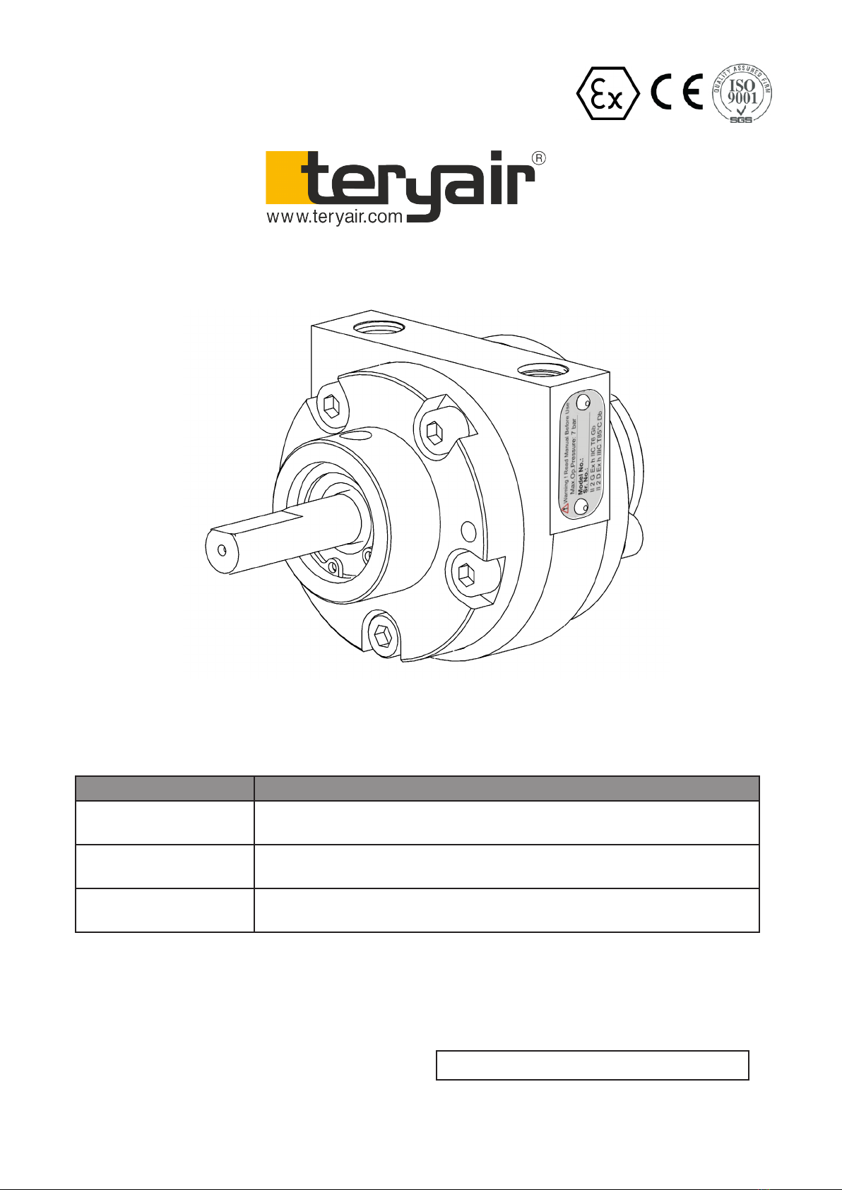
1 VM SG Iron and Stainless Steel Construction, All variants
Models Descriptions
1VMSXXXX FOOT Model with Lube / Lube-Free, SG Iron / SS & NPT / BSPT
Variants
1VMTXXXX HUB Model with Lube / Lube-Free, SG Iron / SS & NPT / BSPT
Variants
1VMNXXXX NEMA Model with Lube / Lube-Free, SG Iron / SS & NPT / BSPT
Variants
1 V M
Read this manual carefully before installing, operating or servicing this equipment. It’s the responsi-
bility of the employer to ensure this manual is read by the operator. Please preserve this manual.
is document is issued with Product Serial No
Operation and Maintenance Guide
<<Serial No>>

FF-MM-00-REV - 00
Page 2
Operation and Maintenance Guide 1 VM Air Motor Series
Table of Contents
3 Nomenclature
3 Technical Data
4 SafetyInstrucons
5 InstallaonInstrucons
6 Operanginstrucons
7 SuggestedLubricants
7 Troubleshoong
8 DisassemblyandRe-assembly
9 ExplodedViewfor1VMAirMotor
10 BillofMaterialsfor1VMSeries(SGIron)
11 BillofMaterialsfor1VMSeries(SS)
12 DimensionalData
13 RepairKitsfor1VM
14 EuDeclaraonOfConformity
15 WarrantyCercate

FF-MM-00-REV - 00
Page 3
Operation and Maintenance Guide 1 VM Air Motor Series
1000 5000
40002000 3000 70006000
SPEED in rpm
0.1
0
0.5
0.4
0.3
0.2
in HP
POWER
0.4
0.3
0.2
0.1
0
in kW
Power
Torque
@100 psi
@80 psi
1 VM
6
4.8
3.6
2.4
in lbs-in
1.2
0
TORQUE
0.65
0.52
0.35
0.17
0
in Nm
@40 psi
@60 psi
@20 psi
@100 psi
@80 psi
@60 psi
@40 psi
@20 psi
Air supply Pressure
@100 psi = 7bar = 7Kg/cm2
5
0
1000 5000
40002000 3000 70006000
SPEED in rpm
AIR CONSUMPTION
25
20
15
10
36
27
18
9
0
in cubic feet/min
in mt3/hr
Air
Consumption
@100 psi
@80 psi
1 VM
@40 psi
@60 psi
@20 psi
Air supply Pressure
@100 psi = 7bar = 7Kg/cm2
Power and Torque Graphs 1VM Air Consumption Graph 1VM
Air Motor Nomenclature
X XX X X X X X
Size Motor Type Mounting Lubricated or
Lube-Free
Material of
Construction
Threading on
Inlet and Outlet
Rotating
Direction
1
2
4
6
8
16
VM - Vane Type
PM - Piston Type
VG - Vane Geared
PG - Piston Geared
L - Face Type
S- Foot Type
T - Hub
D - IEC Flange Type
N - NEMA Flange Type
A- Lubricated
O - Lube Free
L - SG Iron
S - SS316
R- NPT
G - BSPT
C - Clockwise
A - Anticlockwise
For example, 1VMTALRC is a size 1, Vane type, Hub Mounted, Lubricated, SG Iron MOC, NPT threading with Clockwise
Rotation
Technical Data 1 VM
Model 1 VM Air Motor (Clockwise) 1 VM Air Motor (Anticlockwise)
Power upto 0.31kW (0.42HP)
Torque upto 0.63 Nm (5.6 lbs-in)
Air Consumption 0 to 34.8m3/hr (0 to 20.5 cfm)
Motor Weight 0.9kgs (2lbs)
Operating Pressure 1.4 to 7kg/cm2 (20 to 100PSI)
Max Allowable speed 7000 rpm (ATEX limit)*
FF-MM-00-REV - 00
Page 4
Operation and Maintenance Guide 1 VM Air Motor Series
Safety Instructions
Warning: If not followed could
cause personal injuries
Caution: If not followed could result in damage
to equipment.
Warning
is manual must be read and the operating
instructions carefully followed.
Warning
Safety and protective clothing, eyewear, head-
gear, ear protection, gloves and footwear to be
worn during operation of this Vane motor.
Caution
Install proper guard around the output sha as
needed.
Warning.
Operators under 18 not allowed to operate this
Vane motor operators must be made familiar
with the instructions in this manual before
attempting to operate the Vane motor Ensure
that job site is clear of bystanders. Do Not
dis-assemble in explosive atmosphere.
Caution
Use only genuine Teryair or Teryair approved
accessories.
Warning
is Vane motor is designed for use in an ex
p losive environment for Zone 1 & 2 for Gas
and Dust.
Warning
Operate the motor for approximately 2 hours at
the maximum desired load. Measure the sur-
face temperature of the motor on the casting
opposite the pipe ports. e maximum surface
temperature listed on the motor is for nor-
mal environmental and installation conditions.
Fort air motors Temp. Class T6 (Gas) and T85°
C (Dust). e maximum surface temperature
Ex code
ll 2 G Ex h IIC T6 Gb
ll 2 D Ex h IIIC T85° C Db
Amb. Temp ( +1° C to +40° C)
Checklist for installation in
hazardous areas
Read air motor label to check that motor has
been designed for use in a hazardous
application:
• Hazardous zone
• Hazardous category
• Equipment group
• Temperature class
• Maximum surface temperatures
Intended And Prohibitive Use
Intended Use
Marine and Oshore industries. Can be in
various application subjected to availability of
air pressure.
e design of this pneumatic vane motor is
conrming to EN/ ISO 80079-36 and 80079-37
explosive atmosphere suitable to use in zone 1
& 2 area, gas group IIC and Dust group IIIC,
temp. Class T6 (85°C).
i. EN / ISO 80079-36 : 2016 : Explosive
atmospheres—Part 36 :Non-electrical
equipment for explosive atmospheres—
Basic metod and requirements
ii. EN / ISO 80079-37 : 2016 : Explosive
atmospheres—Part 37 : Non-electrical
equipment for explosive atmospheres—
Non-electrical type of protection construction-
al safety ‘c’, control of ignition sources ‘b’, liquid
immersion ‘k’.
Prohibitive use
Use with non-genuine spare parts or
accessories is prohibited
Following symbols are used through out this
manual.

FF-MM-00-REV - 00
Page 5
Operation and Maintenance Guide 1 VM Air Motor Series
Warning
Check the site to make sure that the Vane
motor will be adequately ventilated and that
there is no external heat input.
Caution
Completely turn o the Vane motor and
disconnect air supply line before attempting
any service. Read Assembly and Dis-assembly
instructions.
Warning
Do not use a hammer on the sha or
connections.
Do Not dis-assemble in explosive atmosphere.
Warning
Take care not to exceed the supply air pressure
maximum 7kg/cm²(100 psi) for Lubricated
and maximum 5.6 kg/cm²(80 psi) for Lube-
free .
Caution
Do not exert excessive pressure against the
work surface. Keep hoses in good condition.
Check hoses for signs of wear, cracks & bulges
and ensure that they are secure. Accidental
disconnection while hose is pressurized makes
the hose whip and can be a safety hazard.
Caution
• Please check the hose connection prior to
starting motor
• Keep hands & clothing away from
moving parts.
• Store these Vane motors in secure & dry
environment.
• Do not modify this Vane motor in any way
as this will invalidate the warranty and
could lead to serious injury.
• Do not drag this Vane motor by air hose.
should not exceed 80º C. Do not continue
to operate the motor if the measured surface
temperature exceeds temperature listed on the
motor. If your measured temperature does ex-
ceed listed value, consult with your Distributor
/ Representative for a recommendation.
Installation Instructions
An automatic air line lubricator should be in-
stalled in the air line as close as possible and no
more than 18inches (1/2 meter) from the air
motor. Install the lubricator level with or above
the air motor so that the oil mist will blow direct-
ly into or fall down into the motor. Install a ilter
in the air line before the connection to the motor.
Next install an air pressure regulator to control
motor speed and torque.
Clean the compressed air connection with low
pressure air to remove any dirt from the line
before connecting to the ports. Use the proper
sized fasteners. For the most ecient output and
control of speed, use air lines that are the same
size as the motor inlet port if the connection is
less than 7 feet (2 meters). For longer connec-
tions, use the next pipe size larger than the motor
intake port. Connect lines to motor in the proper
direction
Safety wear mandatory while operating Vane
motor
Air stream from product may contain solid o
liquid particle that can result eye or skin dam
age.Eye and face and ear protection must be
worn at all times during operation
Suitable gloves must be worn at all times during
operation.
Operators must wear helmets of suitable
strength at all times. Helmet must be able to
withstand 10G in 8ms without fracturing.
Waterproof heavy duty outerwear and Shoes
with toe cap protection are a must during
operation

FF-MM-00-REV - 00
Page 6
Operation and Maintenance Guide 1 VM Air Motor Series
Daily Before Operating
1. Disconnect air line and muer.
2. Add ushing solvent directly into motor. If
using liquid solvent pour in 1 to 2 ounces of
recommended oil into the motor.
3. Rotate the sha by hand in both directions for
a few minutes.
4. You must wear eye protection for this step.
Cover exhaust with a cloth and reconnect the
air line.
5. DO NOT use kerosene or ANY other
combustible solvents to ush this product.
6. Restart the motor at a low pressure of
approximately 10 PSI/0.7 bar until there is no
trace of solvent in the exhaust air.
7. Listen for changes in the sound of the motor.
If motor sounds smooth, you are nished.
If motor does not sound like it running
smoothly, installing a service kit will be
required.
Air Supply
e air should be clean and dry. Supply
air pressure maximum 7kg/cm²(100 psi) for
Lubricated and maximum 5.6 kg/cm²(80 psi) for
Lube-free.
Hoses
• Daily before operation check the hoses,
especially the high pressure hoses for damage
or leaks
• Use genuine Teryair spares and if possible
mention the serial number of the Vane motor
when ordering spares.
Operating instructions
Vane motors are rugged dependable product
designed to give you years of satisfactory
service. Follow the instructions mentioned here
to enhance life and performance. Check the
direction of the motor airow. A single rotation
motor will operate properly only in one
direction.Single rotation motors require a
muer to be connected to the air port. Remove
the plastic shipping plugs from the ports. Save
plugs for future use during shutdown.
Mounting
is product can be installed in any orientation.
Mount the motor to a solid metal base plate that is
mounted to a stable, rigid operating surface. Use
shock mounts to reduce noise and vibration. Install
a pressure regulator or simple shut-o valve to
control motor.
Storage
• It is your responsibility to follow proper
shutdown procedures before storage.
• Turn o air intake supply.
• Disconnect air supply and vent all air lines.
• Remove Vane motor from connecting
machinery.
• Remove the muer.
• Wear eye protection. Keep away from air stream.
Use clean, dry air to remove condensation from
the inlet port of the motor.
• Lubricate motor with a small amount of oil into
the intake port. Rotate sha by hand several times
to distribute oil.
• Plug or cap each port.
• Coat output sha with oil or grease.
• Store motor in a dry environment.
Lubrication Requirements
Lubricated Vane motor: Always install a line
lubricator on the air line as close to the Vane motor
as possible. A Filter Regulator Lubricator unit (FRL)
is strongly recommended. Keep the lubricator bowl
topped up with recommended grade of oil and check
that the oil is reaching the Vane motor Running the
Lubricated Vane motor without lubrication is likely to
cause damage to the components causing premature
replacement.

FF-MM-00-REV - 00
Page 7
Operation and Maintenance Guide 1 VM Air Motor Series
Troubleshooting
L ow Torque Low Speed Won’t run Runs well but
slows down Reason & Remedy for problem
√ √ √ Dirt or foreign material present. Inspect
and ush.
√ √ √ Internal rust. Inspect and ush.
√ √ Low air pressure. Increase pressure.
√ Air line too small. Install larger line(s).
√ √ Restricted exhaust. Inspect and repair.
√ √ √ √ Motor is jammed. Have motor serviced.
√ √ Air source inadequate. Inspect and repair.
√ √ Air source too far from motor. Recongure
setup.
Suggested Lubricants
Brand Above 27 Deg C ( From 5 Deg C to 27 Deg C Below 5 Deg C
Shell Toona R 72 Toona R 41 Toona R 27
Mobil Almo 529 Almo 527 Almo 525
Esso -- Arox EP.65 Arox EP.45
Caltex Rando Oil 100 Rando Oil 100 Rando Oil 46
Texaco -- -- Airolene Tool OiI
Daltron Regal Oil F (R&O) Regal Oil PE(P&E) Regal Oil PE(R&O)
Burmah Castrol Silkolene 881 Silkolene 548/T Silkolene 733
BP Castrol RD Oil 3 Castrol RD Oil Light Megna SPX
Duckham Garnet 7 Garnet 6 Zero Fio 5
Sternol Merlin 87 Merlin 71 Merlin 54

FF-MM-00-REV - 00
Page 8
Operation and Maintenance Guide 1 VM Air Motor Series
Dis assembly and Re-assembly
a. Unscrew readed Bearing Cap (5) from
Rear Flange (3). Remove O-ring (8) on bearing
Cap (5) and replace with new one (if found dam-
aged).
b. Unscrew Allen Bolt (14) from Rear Flange
(3) from housing (1) to replace shim (6) (While
assembly ensure holes of Housing, Rear Flange
and Shim are aligning together) with new one (if
found damaged).
c. Now remove Ball bearing (9) from Rear
ange (3) using mallet and replace it with new
one (if worn-out).
d. Remove the Rotor Sha (4) with Rotor
blades from Housing (1). Now remove the Rotor
Blades (7) from Rotor Sha (4) and replace them
with new Rotor Blades. (While assembly ensure )
e. From front side of motor remove Internal
Circlip (12) using circlip plier from Front ange
(2) then remove Carbon Seal (11). Now remove
Ball bearing (10) by using puller and replace it
with new ones (bearing & carbon seal).
f. Aer installation of bearing & seal then
install the Internal Circlip (12) using circlip plier
in the internal groove of Front ange (2).
g. Now place Rotor Blades (7) inside the
Groove of Rotor Sha (4) such that tapers on
Rotor blades are facing towards rotor as shown in
the exploded view.
h. Now install the above Rotor Sha assem-
bly into the Housing (1) and Front Flange bearing
using press/mallet precisely and ensure that rotor
face is not above the housing face.
i. Now follow the above steps c, b, in reverse
manner to assemble the motor.
j. Now aer assembly, ensure that Rotor Sha
(4) is rotating smoothly inside else tap lightly on
the rotor sha front end or rear end until you ob-
tain smooth rotation of rotor sha (4).
k. Once smooth rotation is achieved follow
the step ‘a’ and complete the assembly.

FF-MM-00-REV - 00
Page 9
Operation and Maintenance Guide 1 VM Air Motor Series
Exploded View for 1 VM Air Motor
1
2
3
4
5
6
7
89
10 11
13
14
15
12
16
17
18
HUB
FOOT
NEMA
13
210 11 12

FF-MM-00-REV - 00
Page 10
Operation and Maintenance Guide 1 VM Air Motor Series
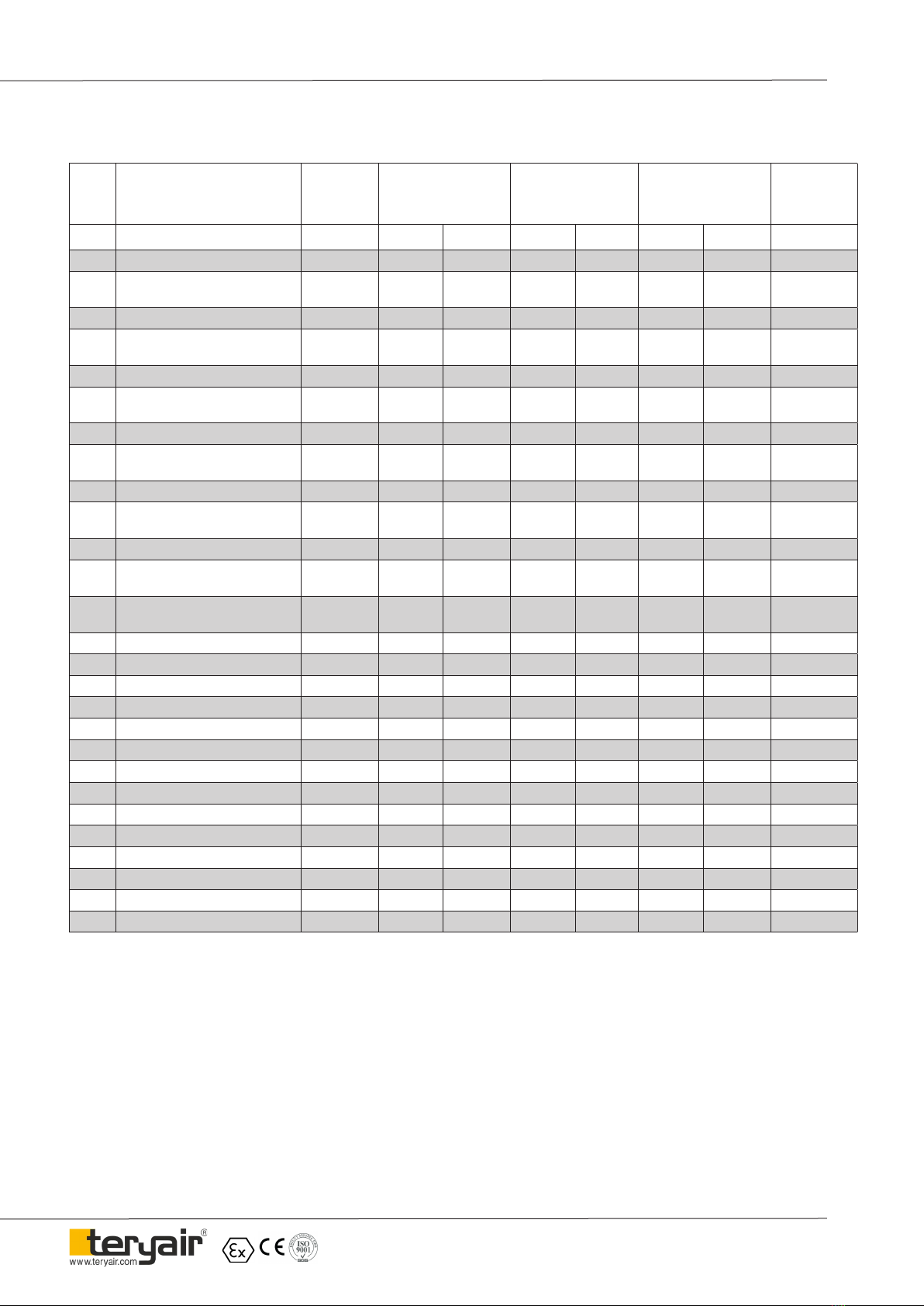
Bill of Materials for 1VM Clockwise (SG Iron)
Illu.
No. Description Part
Number HUB FOOT NEMA
REPAIR
KIT
8119702
1VMTAL 1VMTOL 1VMSAL 1VMSOL 1VMNAL 1VMNOL
1* HOUSING -1/8"NPT 1VM-UD 811 05 08 1 - 1 - 1 -
1* HOUSING -1/8"NPT 1VM-UD
(LUBE-FREE)
811 05 08LF - 1 - 1 - 1
1** HOUSING -1/8"BSPT 1VM-UD 811 05 09 1 - 1 - 1 -
1** HOUSING -1/8"BSPT 1VM-UD
(LUBE-FREE)
811 05 09LF - 1 - 1 - 1
2 FRONT FLANGE FOR 1VM-C 811 05 11 1 - 1 - - -
2 FRONT FLANGE FOR 1VM-C
(LUBE-FREE)
811 05 11LF - 1 - 1 - -
2 NEMA FLANGE FOR 1VM-C 811 05 12 - - - - 1 -
2 NEMA FLANGE FOR 1VM-C
(LUBE-FREE)
811 05 12LF - - - - - 1
3 REAR FLANGE FOR 1VM-C 811 05 13 1 - 1 - 1 -
3 REAR FLANGE FOR 1VM-C
(LUBE-FREE)
811 05 13LF - 1 - 1 - 1
4 ROTOR SHAFT FOR 1VM-C 811 21 09 1 1 1 1 - -
4 ROTOR SHAFT FOR 1VM-C -
NEMA
811 21 10 - - - - 1 1
5 THREADED BEARING CAP
FOR 1VM-UD
811 21 08 1 1 1 1 1 1
6 SHIM OD55 x ID38 X 0.030 THK. 811 37 02 2 2 2 2 2 2 2
7 ROTOR BLADE FOR 1VM-UD 811 39 02 4 4 4 4 4 4 4
8 'O' RING 811 40 01 1 1 1 1 1 1 1
9 BALL BRG.(609) 811 50 01 1 1 1 1 1 1 1
10 BALL BRG.(61900) 811 50 02 1 1 1 1 1 1 1
11 CARBON SEAL 811 21 11 1 1 1 1 1 1 1
12 INTERNAL CIRCLIP 500 90 43 1 1 1 1 1 1
13 GRUB SCREW M4x5L HT Blk 811 90 07 2 2 2 2 2 2
14 S.H.C.S. M5-0.8Px12L-HT Blk 550 90 28 10 10 7 7 10 10
15 FOOT 811 31 01 - - 1 1 - -
16 S.H.C.S. M5-0.8Px25L-HT Blk 550 90 56 - - 3 3 - -
17 SPRING WASHER M5 x 1.6 THK 805 90 01 - - 3 3 - -
18* MUFFLER 1/8" NPT 811 50 07 1 1 1 1 1 1
18** MUFFLER 1/8" BSPT 811 50 08 1 1 1 1 1 1
Note -1) „ * „ Marks part are applicable for NPT Models Only
2) “ ** “ Marks part are applicable for BSPT Models Only
FF-MM-00-REV - 00
Page 11
Operation and Maintenance Guide 1 VM Air Motor Series
Bill of Materials for 1VM Anti-Clockwise (SG Iron)
Illu.
No. Description Part
Number HUB FOOT NEMA
REPAIR
KIT
8119702
1VMTAL 1VMTOL 1VMSAL 1VMSOL 1VMNAL 1VMNOL
1* HOUSING -1/8"NPT 1VM-UD 811 05 08 1 - 1 - 1 -
1* HOUSING -1/8"NPT 1VM-UD
(LUBE-FREE)
811 05 08LF - 1 - 1 - 1
1** HOUSING -1/8"BSPT 1VM-UD 811 05 09 1 - 1 - 1 -
1** HOUSING -1/8"BSPT 1VM-UD
(LUBE-FREE)
811 05 09LF - 1 - 1 - 1
2 FRONT FLANGE FOR 1VM-A 811 05 10 1 - 1 - - -
2 FRONT FLANGE FOR 1VM-A
(LUBE-FREE)
811 05 10LF - 1 - 1 - -
2 NEMA FLANGE FOR 1VM-A 811 05 06 - - - - 1 -
2 NEMA FLANGE FOR 1VM-A
(LUBE-FREE)
811 05 06LF - - - - - 1
3 REAR FLANGE FOR 1VM-A 811 05 07 1 - 1 - 1 -
3 REAR FLANGE FOR 1VM-A
(LUBE-FREE)
811 05 07LF - 1 - 1 - 1
4 ROTOR SHAFT FOR 1VM-A 811 21 12 1 1 1 1 - -
4 ROTOR SHAFT FOR 1VM-A -
NEMA
811 21 06 - - - - 1 1
5 THREADED BEARING CAP
FOR 1VM-UD
811 21 08 1 1 1 1 1 1
6 SHIM OD55 x ID38 X 0.030 THK. 811 37 02 2 2 2 2 2 2 2
7 ROTOR BLADE FOR 1VM-UD 811 39 02 4 4 4 4 4 4 4
8 'O' RING 811 40 01 1 1 1 1 1 1 1
9 BALL BRG.(609) 811 50 01 1 1 1 1 1 1 1
10 BALL BRG.(61900) 811 50 02 1 1 1 1 1 1 1
11 CARBON SEAL 811 21 11 1 1 1 1 1 1 1
12 INTERNAL CIRCLIP 500 90 43 1 1 1 1 1 1
13 GRUB SCREW M4x5L HT Blk 811 90 07 2 2 2 2 2 2
14 S.H.C.S. M5-0.8Px12L-HT Blk 550 90 28 10 10 7 7 10 10
15 FOOT 811 31 01 - - 1 1 - -
16 S.H.C.S. M5-0.8Px25L-HT Blk 550 90 56 - - 3 3 - -
17 SPRING WASHER M5 x 1.6 THK 805 90 01 - - 3 3 - -
18* MUFFLER 1/8" NPT 811 50 07 1 1 1 1 1 1
18** MUFFLER 1/8" BSPT 811 50 08 1 1 1 1 1 1
Note -1) „ * „ Marks part are applicable for NPT Models Only
2) “ ** “ Marks part are applicable for BSPT Models Only

FF-MM-00-REV - 00
Page 12
Operation and Maintenance Guide 1 VM Air Motor Series
Foot Mounting 1VM
Hub Mounting 1VM
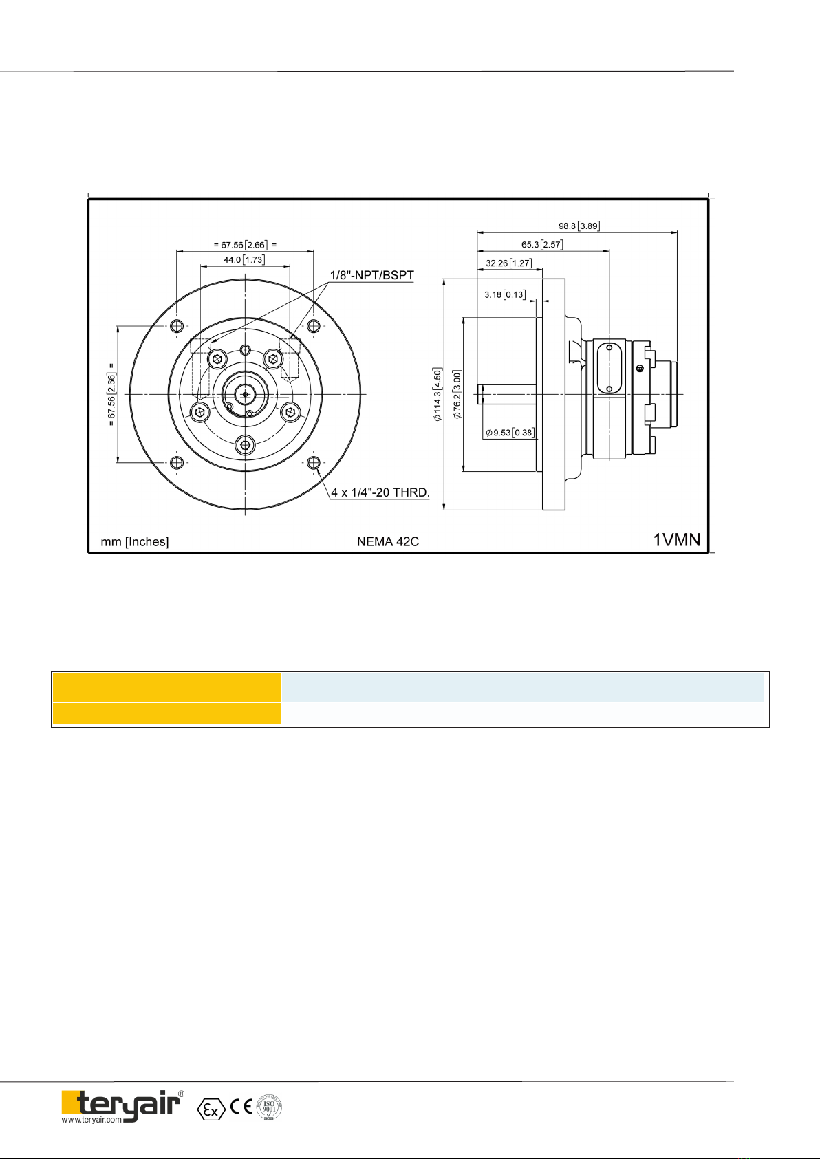
Dimensional Data
FF-MM-00-REV - 00
Page 13
Operation and Maintenance Guide 1 VM Air Motor Series
NEMA Flange Mounting 1VM
Repair KIT Ordering No Suitable for
811 97 02 Suitable for 1 VM all variants
Repair Kits for 1VM Air Motor (Clockwise / Anticlockwise)
Note - Repair Kit includes Blades, Bearings, Shims, Ejection rings, Oil Seals and O rings

FF-MM-00-REV - 00
Page 14
Operation and Maintenance Guide 1 VM Air Motor Series
EU DECLARATION OF CONFORMITY
Object of declaration
PRODUCT : PNEUMATIC VANE MOTOR
MODEL : <<Model Number>>
MANUFACTURER’S NAME : TERYAIR EQUIPMENT PVT. LTD.
ADDRESS : SITE - 1: BUILDING A - 1/2, 102 TO 105 & BUILDING C 12 & 13,
TIRUPATI UDYOG NAGAR, SATIVALI ROAD, VASAI (E),
PALGHAR : 401208.
SITE - 2: AUGUSTINE - II, COLACO INDUSTRIAL COMPLEX, GALA NO
101 TO 107, SATIVALI ROAD, VILLAGE WALIV, VASAI (E), PALGHAR:
401208
To provide presumption of conformity in order to directive 2014/34/EU; the following harmonized standards and/or other
normative documents as referenced within the following ocial journals are applied:
APPLICABLE DIRECTIVE: ATEX DIRECTIVE (2014/34/EU)
APPLICABE STANDARDS:
EN ISO 80079-36: 2016 : Explosive atmospheres —Part 36: Non-electrical equipment for explosive atmospheres
Basic method and requirements.
EN ISO 80079-37:2016 : Explosive atmospheres —Part 37: Non-electrical equipment for explosive atmospheres
Non- electrical type of protection constructional safety ‘c’, control of ignition sources ‘b’,
liquid immersion ‘k’.
Notied body to whom Technical le has logged with: - Technicka Inspekcia (Ref: 1354).
DECLARATION: - TERYAIR EQUIPMENT PVT. LTD., declare that under our sole responsibility for the supply of the
product dened above, the said product complies with all the applicable Directives, Regulations and all essential Health and
Safety requirements applying to it.
I, the undersigned, hereby declare that the product specied above conforms to the above standard(s).
ATEX MARKING APPLIED: ll 2 GD Ex h IIC T6 Gb
Ex h IIIC T85C Db
Signed for and on behalf of
TERYAIR EQUIPMENT PVT. LTD. Place of Issue : Vasai
Date : <<Date>>
FF-MM-00-REV - 00
Page 15
Operation and Maintenance Guide 1 VM Air Motor Series
Warranty Certicate
Every product manufactured by Teryair
is built to meet the highest standards of quality.
Teryair warrants that the Products, accessories and parts manufactured or supplied by the company be
free from defects in material and workmanship for a period of six months from date of Teryair authorized
dealer invoice to customer, or one year from date of Teryair invoice to dealer, whichever is earlier. Failure
due to normal wear, misapplication, or abuse is, of course, excluded from this warranty.
Since the use of Teryair products and parts is beyond our control, Teryair cannot guarantee the suitability
of any product or part for a particular application and Teryair shall not be liable for any consequential dam-
age or expense arising from the use or misuse of its products on any application. Teryair does not war-
ranty bought out products or components such as electric motors and hardware but will assist in directing
warranty queries to the dealer/manufacturer responsible. Teryair responsibility is limited solely to replace-
ment or repair of defective Teryair products or components.
Dealer/End User shall have no right or remedy and Teryair shall have no liability or obligation under the warranty, if: (i) a Product is altered,
changed, modied or tampered with in any way, (ii) a Product is damaged after deposit with the transporter for shipment; (iii) a Product is not
properly preserved, packaged, stored, processed or handled after receipt; (iv) a Product is not used and maintained in accordance with Teryair’s
recommended operating and maintenance manuals, instructions and procedures, if any; (v) a Product is not properly incorporated or installed in,
or not properly combined with, an Other Product; (vi) the issue with a Product is directly or indirectly attributable to, or directly or indirectly results
from or arises out of, a failure, substandard performance or other issue with another product, material, component or part not supplied by Teryair;
(vii) the issue with a Product is directly or indirectly attributable to, or directly or indirectly results from or arises out of, compliance with any de-
sign, specication or other specic requirement of Dealer/End User; (viii) a Product is used in a manner, with a substance or for a purpose other
than the normal manner, substance and purpose for which it is intended or is otherwise subjected to abnormal use or service; (ix) a Product is
subjected to a power surge, brown out or other similar occurrence; (x) the issue with a Product is directly or indirectly attributable to, or directly or
indirectly results from or arises out of, normal wear and tear of such Product (including, without limitation, things such as worn seals, diaphragms,
balls, O rings, gaskets, chisels, cutters, hoses and other such wearing components; (xi) the issue with a Product is directly or indirectly.
Model Number : <<Model Number>>
Serial Numbar : <<Serial No>>
Dated : <<Date>> Ajay Bhagat, Q.A. Manager
(Company Seal)

FF-MM-00-REV - 00
Page 16
Operation and Maintenance Guide 1 VM Air Motor Series
is page is intentionally
Le blank.
This manual suits for next models
8
Table of contents
Other Teryair Industrial Equipment manuals


Popular Industrial Equipment manuals by other brands

PCB Piezotronics
PCB Piezotronics IMI SENSORS M080A121 Installation and operating manual

Eaton
Eaton RMQ-M1C-ASI Instruction leaflet

Wilo
Wilo SiBoost Smart Helix V Series Installation and operating instructions

STEPCRAFT
STEPCRAFT Touch Probe P100 operating manual

Lukas
Lukas KSV11 operating instructions

Renishaw
Renishaw Equator EQ-ATS installation guide


Carrier
Carrier 69NT40-541-001 Operation and service

Simpro
Simpro MegaDumper Hazard and Risk Assessment Guide

bonitron
bonitron M3484 Customer Reference Manual

Technom
Technom Lokring MTK45 Instruction card

Schmalz
Schmalz SNGi-AE operating instructions

Conductix-Wampfler
Conductix-Wampfler 0832 operating instructions