manuals.online logo
Brands
  1. Home
  2. •
  3. Brands
  4. •
  5. Woodhaven
  6. •
  7. Tools
  8. •
  9. Woodhaven 7500 User manual

Woodhaven 7500 User manual

7500
Dovetail Jig
Owners Manual
PLEASE READ CAREFULLY!
Tools needed for assembly:
Phillips screwdriver
7/16" wrench
Portable mode set-up
Stationary mode set-up
Shown with optional 6104 Kamtite Clamps
2
C
A
G
D
N
Qty Part# Description
17 5760B oval nut
Qty Part# Description
6 5771B 3/4" screw
Qty Part# Description
4 HB040A 1-1/4" hex bolt
Qty Part# Description
10 NUT010A locknut
Qty Part# Description
4 HB060 3" hex bolt
Qty Part# Description
9 MF015 1" screw
Qty Part# Description
4 Spring2 Spring
Qty Part# Description
4 HB020 3/4" hex bolt
F
B
E
Qty Part# Description
4 WFN002 1" washer
L
Qty Part# Description
1pr 7500S Stops
H
Qty Part# Description
4 WN003 1-1/4" nylon washer
I
M
Qty Part# Description
4 5560 wing knob
7500H Hardware
Before beginning, identify and verify that you have all the hardware shown
List of additional parts not shown in
hardware drawings - refer to photos
in instructions:
Qty PN Description
1 7500G MDF Base
2 7500I Side Supports
1 7500A Front Support
1 7500T Dovetail Template
1 7500B 16-1/2" Clamp Bar
1 7500C 15" Clamp Bar
1 7500D 18-3/4" Clamp Support
1 7500E MDF Router Support
1pr 7500F Support Arms, alum.
2 7500M Clamp Bar Strips
In addition to the above parts you
should have a bag of hardware con-
taining the parts shown in the hard-
ware drawings
Qty PN Description
1 7500H Hardware Pkg.
Qty Part# Description
2 5590 ball knob
J
7/16" spacing
Right Stop
Left Stop
3/4" spacing
K
Qty Part# Description
2 7500RS Support Block
3
BEFORE BEGINNING
Identify and verify that you have all the parts listed.
Read the instructions at least once, familiarizing yourself
with the parts, before beginning assembly.
ATTACH SUPPORTS TO BASE
Attach the Side Supports and the Front Support
(7500I & 7500A) to the MDF Base (7500G) with the 1/4-
20 x 1" screws (E-MF015) and oval nuts (B-5760B).
Insert the screws through the countersunk holes in the Base
and start the oval nuts on the screws. The Front Support
has a small opening machined in the lower T-slot on one
side and none in the opposite side. The side without the
opening faces towards the long straight edge of the Base,
the side with the opening faces towards the cutout in the
Base. Slide the Front Support on the three oval nuts along
the long edge of the Base. Slide the Side Supports on to
the two oval nuts on either side. See fig. 1.
Make sure the Side Supports are butted up against the
Front Support and both ends of the Front Support are flush,
or nearly so, with the Side Supports. Tighten the screws
and set the assembly down on the Base. See fig. 2 & 3.
Qty Part# Description
2 5780B 1-1/2" socket hd.bolt
Q
Qty Part# Description
16 WN001 11/16" nylon washer
Qty Part# Description
2 PS001 1/2" spacer
R
Qty Part# Description
4 PS007 1/4" spacer
V
Qty Part# Description
2 PS009 7/8" spacer
T
Qty Part# Description
1 780 dovetail bit
P
S
O
U
Qty Part#
18 WB002
Description
brass washer
Qty Part#
4 5520
Description
brass knob
7500H Hardware
Before beginning, identify and verify that you have all the hardware shown
Fig. 1
Fig. 2
7500G
MDF Base
7500G
MDF Base
7500A
Front
Support
Small machined
opening faces
towards cutout
in Base.
7500A
Front
Support
7500I Side
Supports
7500I Side
Supports
W
Qty Part# Description
4 5772B 1" screw
Fig. 3
Completed Base
Assembly
4
ATTACH DOVETAIL TEMPLATE
Attach the Dovetail Template (7500T) to the Side sup-
ports and the Front support. Place one oval nut (B-5760B)
into the top T-slot of both Side Supports. Place two oval
nuts in the top T-slot of the Front Support, one on either side
of the cutout area. See fig. 4.
The directions show the Template's 7/16" dovetail spac-
ing placed to the front. Put the 3/4" dovetail spacing to the
front if desired. Lay the Template on top of the Supports to
check that the oval nuts are aligned with the mounting holes
and slots in the Template. The Template should overhang the
Front Support approximately 3/8" and be more or less flush
with the ends of the Front Support. Remove the Template
and reposition the oval nuts until they are in the correct posi-
tion to fasten the Template. Install a brass washer (U-
WB002) in the mounting holes and slots of the Template.
Insert 3/4" screws (D-5771B) through the holes and slots and
into the oval nuts and tighten for now. The Template posi-
tion will be re-adjusted later. See fig. 5 & 6.
INSTALL STOPS
Get the Stops (H-7500S) and study them. Note in the
part drawing we indicate which side of the stop is for the
7/16" and 3/4" spacing and which is the right and left Stop.
The stops are stamped with an Rand an Lto indicate right
and left. The Template spacing selected will determine
which Stop spacing to use. The Stop spacing should always
match the Template spacing. The Stops, when attached to the Front
Support as shown in the Stop part drawing, would be the correct setup for
7/16" dovetails. Flipping the Stop over so the 3/4" spacing is on top would
be the correct setup for 3/4" dovetails. Note that when the Stop is flipped
over to use the 3/4" spacing, the surface is machined and lighter in color
then the side with the 7/16" spacing. This will help you in identifying the
Stop spacing. Also note that whichever spacing is at the top, there is a steel
pin that projects out the back of the Stop at the top and another that projects
out the front of the Stop at the bottom. The pin projecting out the back of
the Stop near the top must always be positioned just inside the cutout area
in the Front Support..
Get the two 3/4" hex bolts (C-HB020). Slide the head of the bolt in to
the top T-slot of the Front Support, one on either side of the cutout area.
Place the Left Stop on the bolt to the left of the cutout and the Right Stop
on the bolt to the right. Fasten the Stop to the bolt with the brass knob (S-
5520).See fig. 7-9.
The Stops should be positioned on either side of the cutout (top pin of
Stop projecting backwards into the cutout area) and against the underside of
the Template. Position the Stops so they're 1" in from the ends of the Front
Support. See fig. 7 & 8. This is the starting position for the Stop. See
STOP SPECS for more details. Re-adjust the Template so it's flush with
the face of the Stops. See fig. 9.
1"
Dovetail Template
7500T Dovetail Template with
7/16" template spacing to front
7500A
Front
Support
7500I
Side
Support
Oval Nuts
Fig. 4
Fig. 5
Fig. 6
Fig. 8
Fig. 7
7500S
Left Stop 7500S
Right Stop
1"
Fig. 9 Side View
Stop snug
against under-
side of
Template.
Template edge
flush with face
of Stop.
5
ATTACH CLAMP BAR TO
FRONT SUPPORT
Insert two 3" hex bolts
(G-HB060) into the lower T-slot of the Front Support thru
the machined opening in the back of the Front Support.
See fig. 10. Install the bolts so they project out the front of
the Front Support, with the hex head of the bolt captured in
the T-slot at the back. See fig. 11. Slide one to the left and
the other to the right, until they're about 10" apart. Install a
11/16" nylon washer (O-WN001), a brass washer (U-
WB002) and a locknut (A-NUT010A) on each bolt.
Tighten the locknut until snug, then loosen it about 1/4th
turn, or until the bolt slides smoothly in the T-slot. Install a
spring (N-SPRING2) and a 11/16" nylon washer (O-
WN001) on each bolt. See fig. 12.
Install the 15" Clamp Bar (7500C) on both bolts.
Install a 1-1/4" nylon washer (I-WN003), a 1" washer (L-
WFN002) and a wing knob (M-5560) on the bolts. Note:
Fig. 12 shows the optional Kamtite Clamps and not the
wing knobs. Install two 1-1/4" hex bolts (F-HB040A), one
at each end of the clamp bar, in the lower T-slot at the front
of the Front Support. Install a 7/8" spacer (T-PS009) and a
locknut (A-NUT010A) on each bolt. Center the Clamp Bar
on the Front Support. Position the spacers on each side of
the Clamp Bar with about 1/8" clearance and tighten the
nuts. See fig. 13.
DETERMINE HOW JIG WILL BE USED
How you'll use the jig, either in a stationary or
portable mode, determines how the 18-3/4" Clamp Support
and 16-1/2" Clamp Bar are assembled.
Stationary: Jig is stationary (on workbench), router moves
over jig. See fig 14.
Portable: Jig moves, router is stationary in a router table.
See fig 15.
Stationary use - pros: Most common way to use jig. May
be method you're already using and are comfortable with.
Best method for long parts. Only way to use the optional
7506K or 7508K templates.
Stationary use - cons: Easier to accidentally tip your
router, destroying some of the Dovetail Template fingers.
Our Router Support will help prevent this, but can't elimi-
nate the possibility.
Portable use - pros: Better control for some people. Less
chance of damaging the Dovetail Template fingers.
Portable use - cons: Least common way to use jig. Too
awkward for long parts. Can't use this method with the
optional 7506K or 7508K templates.
7500A Front Support
Hdw. installed -
ready for Clamp Bar
7500C
15" Clamp Bar
1/8" Clearance
Fig. 11 Fig. 12
Stationary use setup
Portable use setup
Fig. 14
Fig. 15
Fig. 13
Fig. 10
7500A Front Support
Bolt installed from back
6
CLAMP BAR STRIPS
Peel the paper backing off the Clamp Bar Strips (7500M) and
install them on the inside face of the Clamp Bar and the Clamp Bar
support where shown. See fig. 20A. They help hold the horizontal
stock tight against the underside of the dovetail template.
CLAMP BAR ASSEMBLY FOR STATIONARY USE
Insert two 3" hex bolts (G-HB060) in the 16-1/2" Clamp Bar
(7500B) so the bolt head fits into the recess in the bar and the
threads of the bolt project out the opposite side of the slot.
See fig. 16. Space the bolts about 10" apart. Install a 11/16"
nylon washer (O-WN001), a brass washer (U-WB002) and a
locknut (A-NUT010A) on each bolt. Tighten the locknut
until snug, then loosen it about 1/4th turn, or until the bolt
slides smoothly in the T-slot. See fig. 17. Install a spring
(N-SPRING2) and a 11/16" nylon washer (O-WN001) on
each bolt. Install the 18-3/4" Clamp Support (7500D) on
both bolts with its counterbored holes facing opposite the
springs. Install a 1-1/4" nylon washer (I-WN003), a 1"
washer (L-WFN002) and a wing knob (M-5560) on the
bolts. See fig. 18.
Install a brass washer (U-WB002) and a 3/4"
screw (D-5771B) into the counterbored holes and attach
an oval nut (B-5760B) on the end of both screws. Slide
the assembly onto the top T-slot of the Side Supports
with the oval nuts captured in the T-slots. Position the
Clamp Support flush with the end of the Side Supports
and tighten the screws. See fig. 25.
CLAMP BAR ASSEMBLY FOR PORTABLE USE
Insert two 3" hex bolts (G-HB060) in the 18-3/4" Clamp Support (7500D)
so the bolt head fits into the recess in the support and the threads of the bolt
project out the opposite side of the slot. See fig. 19. Space the bolts about 10"
apart. Install a 11/16" nylon washer (O-WN001), a brass washer (U-WB002)
and a locknut (A-NUT010A) on each bolt. Tighten the locknut until snug, then
loosen it about 1/4th turn or until the bolt slides smoothly in the T-slot. See fig.
20. Install a spring (N-SPRING2) and a 11/16" nylon washer (O-WN001) on
each bolt. Install the 16-1/2" Clamp Bar (7500B) on both bolts with its recessed
slot facing opposite the springs. Install a 1-1/4" nylon washer (I-WN003), a 1"
washer (L-WFN002) and a wing knob (M-5560) on the bolts. See fig. 21.
Install a brass washer (U-WB002) and a 3/4" screw (D-5771B) into the
counterbored holes at each end of the Clamp Support and attach an oval nut (B-
5760B) on the end of both screws. Slide the assembly onto the top T-slot of the
Side Supports with the oval nuts captured in the T-slots. Position the Clamp
Support flush with the ends of the Side Supports and tighten the screws. See
fig. 25.
To use the jig portably you'll need to install the handle hardware on the
MDF Base. Use the 1-1/2" socket head bolts (Q-5780B), the 1/2" spacers (R-
PS001) and the ball knobs (J-5590) and attach them to the MDF Base as shown.
See fig. 22 & 23
Clamp Bar assembly for
Stationary use
7500D
18-3/4" Clamp Support
7500D
18-3/4" Clamp Support
7500B
16-3/4" Clamp Bar
7500B
16-3/4" Clamp Bar
Fig. 18
Fig. 21
Clamp Bar assembly for
Portable use
Fig. 16 Fig. 17
Fig. 19 Fig. 20
Fig. 22 Fig. 23
Fig. 20A
7500D
7500B
Face these
edges towards
template Apply
7500M
7
ROUTER SUPPORT - FOR STATIONARY USE ONLY
Insert one 3/4" hex bolt (C-HB020) into the lower T-
slot of each Side Support. Install a Support Block (K-
7500RS) and a brass knob (S-5520) on each bolt. See fig.
25. Slide the Support Blocks towards the Front Support
until they can't go any further. The Support Blocks hold the
Router Support at the correct height and will be adjusted
later.
Install two 11/16" nylon washers (O-WN001) on a 1-
1/4" hex bolt (F-HB040A). Insert the bolt through the hole
in the Support Arm (7500F). Install two 11/16" nylon
washers (O-WN001) and an oval nut (B-5760B) on the end
of the bolt. Repeat for the other Support Arm. See fig. 24.
Attach the Support Arms to the Side Supports by slid-
ing the oval nut on the end of the bolt into the upper T-slot
in the face of the Side Support. Position the Support Arm
so it is about 2-3/4" from the end of the Side Support and
tighten the bolt. See fig. 25.
Install a 1" screw (E-MF015) through the holes in the
MDF Router Support and attach an oval nut (B-5760B) to
each screw. Slide the MDF Router Support onto the ends
of the Support Arms with the oval nuts captured in the T-
slot in the top edge of the Support Arms. Position the MDF
Router Support so it's flush with the ends of the Support
Arms and tighten the screws. See fig. 25 & 26.
Set a straight edge on the top of the Template and lift
the Router Support until it contacts the underside of the
straight edge. Loosen the two Support Blocks and slide
them backwards until the Support Block contacts the under-
side of the Support Arm, then tighten the knobs. Place your
router on the Template and Support Arm and check that it
sits flat on the Template. See fig. 26. Readjust as neces-
sary. The Router Support can be swung up out of the way
when installing workpieces in the jig.
7500F
Support Arm
7500F
Support Arm
7500RS
Support
Block
7500RS
Support
Block
7500I
Side
Support
7500E
MDF Router
Support
7500E
MDF Router
Support
2-3/4"
Fig. 24
Fig. 26
Fig. 25
8
INSTALL DOVETAIL BIT
Install the dovetail bit (P-780) in your router. Set the
bit depth at 1-1/32". See fig. 27. This may need to be
adjusted later after making a test cut. As an alternative to
our 780 Dovetail Bit, you can use our 5030 - 5/8" Guide
Bushing, 5040 Locknut and any 1/2" diameter x 14º dove-
tail bit.
MAKE TEST CUT
Use two pieces of wood approximately 8" long by 6"
wide and 1/2" thick. Follow the directions below for a stan-
dard drawer. After you have mastered making a standard
drawer you may want to attempt a rabbeted drawer. See the
RABBETED DRAWER section for instructions on that
process.
STANDARD DRAWER
Place a drawer side in the jig. The inside faces out,
the bottom edge is against the Stop and the end is butted
up against the Template. See fig. 28, 29 & 30.
Slide the clamp bolts as close as possible to the edge
of the part and tighten the clamp. Doing so reduces Clamp
Bar distortion and provides more even clamp pressure.
See fig. 29 & 30.
Slide the mating drawer front (or back) in between the
Clamp Support and the 16-1/2" Clamp Bar and slide it for-
ward until it butts up against the drawer side. The bottom
edge should be against the Stop pin and the inside face
should be against the Template. Slide the clamp bolts as
close as possible to the edge of the part and tighten the
clamp. See fig. 28, 29 & 30.
When using the jig portably, you may
need to insert an additional piece of stock the
same thickness as the drawer front (or back) to
help keep the Clamp Bar level.
CUT THE DOVETAIL JOINT
Set the the router on the Template (or, if
using portably, the Dovetail Jig on the router
table) without the bit touching the work,
Template or Router Support. Turn the router
on and make a scoring cut from right to left
(left to right if using portably) across the face
of the drawer front by skimming across the
ends of the fingers. The scoring cut helps prevent chipping
and tear out during the finish cut. Next, moving from left to
right (right to left if using portably), move the router in and
out of each dovetail finger to finish the cut. See fig. 31.
Sometimes it’s necessary to make a second pass due to
sawdust that may have lodged in the template.
If you notice that the parts moved while machining,
install some 120 to 180 grit self-adhesive sandpaper on the
underside of the Clamp Bars.
Remove the parts and check the fit.
Scoring cut - move right to left
Finish cut - move left to right
Fig. 31
Initial bit depth
1-1/32"
Fig. 27
Fig. 28
Drawer Front or Back
Drawer Side
Drawer setup
Stationary use
Drawer setup
Portable use
Fig. 30
Fig. 29
9
JOINT FIT
The pins (also known as
dovetails) cut in the drawer side
should slide into the sockets (cut
in the drawer front or back) with,
at most, light tapping. The ends
of the drawer sides should be
flush, or inset no more than l/64",
when assembled. This allows the
ends to be sanded flush to the
drawer sides. See fig. 33.
If the drawer sides protrude
past the ends of the drawer front
(or back), then the Template must
be moved back, away from the
face of the Stops. If the ends of
the drawer front (or back) pro-
trude past the drawer sides more
than 1/64", then the Template
must be moved forward so it over
hangs the Stops. See fig. 32. The
Template is adjusted in or out in
relation to the Stops by loosening the Template mounting screws. Make sure you adjust
both sides of the Template equal amounts.
If the joint is too loose, then the cutting depth is too shallow - lower the bit
(portably) or raise the bit (stationary) so it cuts further into the work. If the joint is too
tight, then the cutting depth is too deep - raise the bit (portably) or lower the bit (station-
ary). Bit set deeper = tighter joint. Bit set shallow = looser joint.
INSTALL TEMPLATE STOPS
Once the Template has been adjusted to the best position, install the Template Stops
on the Template. There are four of these, two for each side of the Template. They're
designed to allow you to remove the Template to use the opposite dovetail pattern, then
return to the same setting without having to go through the joint fit process again. Turn
the dovetail jig upside down or on it's side to install the Template Stops. You can also
remove the top clamp bar & support (loosen two screws) to make them easier to install.
Install a brass washer (U-WB002) on two 1" screws (W-5772B). Insert a
screw/washer through the slots (one in each front slot - See fig. 34 & 35.) in the Template
and install a 1/4" spacer (V-PS007), a brass washer (U-WB002) and a locknut (A-
NUT010A) on the screw. See fig. 35.
Slide the spacer/screw up against the back of the Front Support and tighten using an
open end 7/16" wrench and a phillips screwdriver. See fig. 36.
After you have gone through the joint fitting process with the opposite dovetail pat-
tern, repeat the Template Stops installation for that side of the Template also.
Initial Stop Setup
Template set flush
to face of Stop
Moving Template back from
Stop reduces amount drawer
side overhangs drawer front.
Moving Template forward
from Stop increases amount
drawer side overhangs
drawer front.
YES
YES
NO
NO
Rabbeted Front
Standard Front
Fig. 33
Side should be inset 1/64"
or less from end of Face
Fig. 32
Fig. 34
Install Template
Stop here
Fig. 36 Fig. 35
10
STOCK SPECS
This jig is designed for 3/8" to 1" thick stock. 1/2"
stock is the most common thickness used for drawers. The
stock used for the fronts & backs can be a different thick-
ness then the stock used for the sides All stock should be
flat and straight.
Stock thinner than 1/2" may be used for the backs and
fronts, but the ends of the pins (dovetails) will show. Using
thinner stock for the sides will not effect the look of the
joint like it will on the fronts and backs.
We recommend a 1/64" overhang on each end of the
fronts and backs. Cut them 1/32" longer than the desired
finished width of the drawer. See fig. 33, pg. 9 & 38, pg.
12. Cut the sides approximately 9/16" longer (this will
depend on the final cutting depth of the router bit) than the
desired inside length of the drawer.
The width of the stock will depend on the height of the
drawer opening, desired drawer depth and the dovetail pat-
tern selected.
STOP SPECS
The Stops have two offsets on them, a small offset on
one side and a larger offset on the opposite side. See 7500S
Stop part drawing, pg. 2. If you use the 3/4" spacing on the
Template, you also need to use the 3/4" spacing on the
Stops.
The position of the Stops control the dovetail margins
at both edges of the work and also control the inside drawer
depth. Since one effects the other, it is usually best to focus
on the drawer depth you want to achieve. We recommend at
least 1/2" of material on the bottom edge of the drawer. See
fig. 38, pg. 12. After the initial setup, the only time you
need to adjust the Stop position is when you have half a pin
(or less) at the top of the drawer. Then you need to either
re-adjust the Stop position or cut the drawer sides narrower.
The location of the Stop has an effect on the eventual
groove placement for the drawer bottom. The drawer bot-
tom groove normally falls within the first full dovetail pin so
it is hidden after assembly. See fig. 38, pg. 12. Changing
the Stop position effects the groove position, which effects
the inside depth of the drawer.
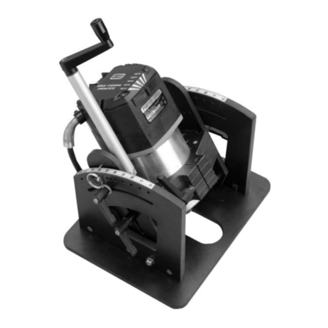
ACCESSORIES
We have several accessories that expand the capabili-
ties of this jig. See the photos to the right.
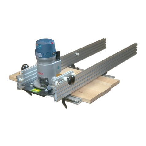
The 7507K Keller Dovetail Kit is for cutting through dove-
tails with a 1-1/8" spacing using our dovetail jig. Includes the tem-
plate and a pair of 1/4" shank carbide tipped bits (one for pins and
one for tails) with shank mounted bearings. Stock capacity is 12"
wide x 1/8" to 3/4" thick.
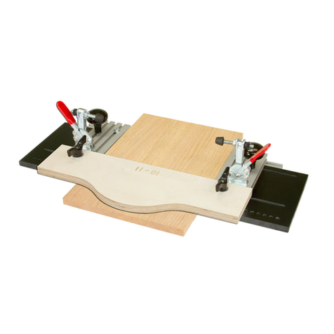
The 7506K Box Joint Kit is for 1/2" & 3/4" box joints and
works on stock up to 3/4" thick. Includes the template (1/2" phe-
nolic) and a 1/2" diameter x 1/4" shank carbide tipped bit with a
shank mounted bearing.
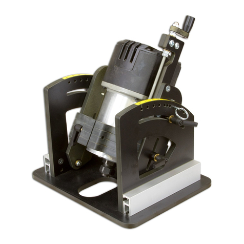
The 7508K Small Dovetail Kit is for 1/4" & 3/8" half-blind
dovetails and works on 3/8" or thicker stock. Includes the template
(1/2" phenolic), 1/4" dovetail bit, 5/16" guide bushing and nut.
The 6104 Kamtite Clamps replace the wing knobs and speed
up the clamping process. Continued
7506K
For 1/2" & 3/4"
Box Joints
7508K
For 1/4" & 3/8"
Half-Blind
Dovetails
7507K
Keller template & bits for
Through Dovetail Joints
11
RABBETED DRAWERS
Rabbeted drawers are drawers with a face that over laps the
cabinet face. The other three drawer parts (both sides and the
back) are of equal width. For a faster way to make Rabbeted
drawers see the QUICK RABBETED DRAWERS section.
The width of the front rabbeted drawer part, measured from
rabbeted shoulders, should equal the width of the side and back
parts. See 38, pg. 12.
The length of the front rabbeted drawer part, measured
from rabbeted shoulders, should equal the length of the back
part. See 38, pg. 12.
A rabbeted drawer front and its adjoining sides must be cut
in separate operations, unlike the parts for a Standard drawer.
The remaining sides and back parts are cut like a Standard draw-
er, in pairs. A Rabbeted drawer will require six setups, one setup
(x 2) for each rear drawer corner and two setups (x 2) for each
front drawer corner.
Rout the mating dovetails into the two front ends of the
adjoining drawer sides. Clamp a piece of scrap where the draw-
er front usually goes, against the drawer side, to prevent split out
as the router bit passes through the drawer sides.
Dovetail the two back corners using the Standard dovetail
technique, doing these parts in pairs.
The rabbet in the drawer front should be at least 5/16" deep
to clear the dovetail bit. See fig. 37.
The bottom edge of rabbeted drawer front must be indexed
against the Stop pin with an additional spacer placed between
the rabbeted edge and the Stop pin to offset it correctly. If you
have a 3/8" wide rabbet and you’re using the 7/16" Template,
you need a 7/8" wide spacer. If a 3/8" wide rabbet and the 3/4"
template, you need a 1-5/8" wide spacer. See fig. 37.
The end of the drawer should be indexed so the shoulder of
the rabbet is aligned with where the front of the drawer side
would be if it were there. You need to make an indexing block
to position the drawer front correctly. Cut a piece of scrap with
the same width rabbet as the drawer front and clamp it in the
front of the dovetail jig where the side would normally go. Face
the rabbeted edge of this indexing block inward, towards the end
of the drawer front, and tighten the front Clamp Bar. Slide the
drawer front forward to index its front edge against the rabbeted
lip in the indexing block and tighten the top Clamp Bar. See fig.
37. Rout both ends of the rabbeted drawer front this way.
QUICK RABBETED DRAWERS
Instead of making a Rabbeted drawer, make a Standard
drawer with the drawer front made of the same wood species as
the desired rabbeted drawer would be. After assembling the
drawer glue a larger drawer front to the standard drawer front.
This provides the same appearance as a one-piece rabbeted
drawer, but is quicker and easier to make.
©Copyright WOODHAVEN INC. 8/27/04
(800) 344-6657 or WWW.WOODHAVEN.COM
Rabbeted Front
Rabbeted Front
Indexing
Block
7/8" wide spacer
Minimum 5/16"
Fig. 37
Rabbeted
drawer setup
detail
12
Rabbeted
Drawer Front -
Inside Face
Standard Drawer Front - Inside Face
Cut 1/32" longer then
desired finished length.
Drawer Back -Inside Face
Cut 1/32" longer then
desired finished length.
A4 A4
D4
D3
C3
C2
A1 A1
B1
B2
Drawer Side -
Inside Face
See
fig.. 33
Drawer Side -
Inside Face
Cut drawer bottom groove
last, 1/2" from bottom edge.
Part marking
suggestion:
mark mating
ends with same
number so you
know to do those
parts as a pair
Fig. 38

This manual suits for next models

1

Other Woodhaven Tools manuals

Woodhaven 8615 User manual

Woodhaven

Woodhaven 8615 User manual

Woodhaven 5432 User manual

Woodhaven

Woodhaven 5432 User manual

Woodhaven 3000 User manual

Woodhaven

Woodhaven 3000 User manual

Woodhaven HD Panel Master 5432 User manual

Woodhaven

Woodhaven HD Panel Master 5432 User manual

Woodhaven Angle-Ease 1470 User manual

Woodhaven

Woodhaven Angle-Ease 1470 User manual

Woodhaven 6002 User manual

Woodhaven

Woodhaven 6002 User manual

Woodhaven 8715 User manual

Woodhaven

Woodhaven 8715 User manual

Woodhaven 8625 User manual

Woodhaven

Woodhaven 8625 User manual

Woodhaven Angle Ease 1425 User manual

Woodhaven

Woodhaven Angle Ease 1425 User manual

Woodhaven 8610 User manual

Woodhaven

Woodhaven 8610 User manual

Woodhaven 6012 User manual

Woodhaven

Woodhaven 6012 User manual

Woodhaven 204 User manual

Woodhaven

Woodhaven 204 User manual

Woodhaven 3000 User manual

Woodhaven

Woodhaven 3000 User manual

Woodhaven EZ Lift 1429 User manual

Woodhaven

Woodhaven EZ Lift 1429 User manual

Woodhaven 7902 User manual

Woodhaven

Woodhaven 7902 User manual

Woodhaven 3210 User manual

Woodhaven

Woodhaven 3210 User manual

Woodhaven 5435 User manual

Woodhaven

Woodhaven 5435 User manual

Woodhaven Angle-Ease 1470 User manual

Woodhaven

Woodhaven Angle-Ease 1470 User manual

Woodhaven 8395 User manual

Woodhaven

Woodhaven 8395 User manual

Woodhaven 8628 User manual

Woodhaven

Woodhaven 8628 User manual

Popular Tools manuals by other brands

Rothenberger ROMAX AC ECO Instructions for use

Rothenberger

Rothenberger ROMAX AC ECO Instructions for use

Macnaught OKTR585-1-001 instruction manual

Macnaught

Macnaught OKTR585-1-001 instruction manual

Prime T1000 Operating instructions manual

Prime

Prime T1000 Operating instructions manual

Di-Acro QUIK-LOK Setup and adjustment

Di-Acro

Di-Acro QUIK-LOK Setup and adjustment

Harbor Freight Tools Pittsburgh 64983 Operator/owner manual & safety instructions

Harbor Freight Tools

Harbor Freight Tools Pittsburgh 64983 Operator/owner manual & safety instructions

Trelawny VLSF1EX Operation and maintenance manual

Trelawny

Trelawny VLSF1EX Operation and maintenance manual

Cessna 310K owner's manual

Cessna

Cessna 310K owner's manual

BorMann PRO BCG1600 user manual

BorMann

BorMann PRO BCG1600 user manual

BorMann PRO BVC6000 manual

BorMann

BorMann PRO BVC6000 manual

Ozito ATK-500 instruction manual

Ozito

Ozito ATK-500 instruction manual

UWAVE UTARGET MANUAL manual

UWAVE

UWAVE UTARGET MANUAL manual

molex 57225-7100 operating manual

molex

molex 57225-7100 operating manual

Sealey AUTO SERVICE VS721.V2 instructions

Sealey

Sealey AUTO SERVICE VS721.V2 instructions

Gesswein Power Hand 2X Z-STX instruction manual

Gesswein

Gesswein Power Hand 2X Z-STX instruction manual

Metabo 341161780 Original instructions

Metabo

Metabo 341161780 Original instructions

Sealey VS4656 instructions

Sealey

Sealey VS4656 instructions

Roth i-press medium UAP3LROTH instruction manual

Roth

Roth i-press medium UAP3LROTH instruction manual

CLYDESDALE CLY 370 BSC user manual

CLYDESDALE

CLYDESDALE CLY 370 BSC user manual

manuals.online logo
manuals.online logoBrands
  • About & Mission
  • Contact us
  • Privacy Policy
  • Terms and Conditions

Copyright 2025 Manuals.Online. All Rights Reserved.