TES 1352H User manual

Sound Level Meter
Datalogger and RS-232 Software
TES-1352H
INSTRUCTION MANUAL
TES ELECTRICAL ELECTRONIC CORP.

CONTENTS
Title Page
1. INSTRUMENT CARE.....................................................................................1
2. FEATURES.....................................................................................................2
3. MEASUREMENT PARAMETERS..................................................................2
4. SPECIFICATIONS..........................................................................................3
5. CONTROLS AND FUNCTIONS.....................................................................6
6. DISPLAY DESCRIPTION...............................................................................8
7. PREPARATION FOR USE.............................................................................9
8. CALIBRATION PROCEDURE ..................................................................... 11
9. MEASUREMENT PROCEDURE..................................................................12
10. STORE/ERASE RECORDED DATA..........................................................12
11. OUTPUT CONNECTORS...........................................................................13
12. RS-232 INTERFACE, SOFTWARE INSTALLATION AND OPERATION..13
※All rights reserved, please do not reprint without the authorization.

1
1. INSTRUMENT CARE
Do not attempt to remove the mesh cover from the microphone as this will cause
damage and affect the accuracy of the instrument.
Protect the instrument from impact. Do not drop it or subject it to rough handling.
Transport it in the supplied carrying case.
Protect the instrument from water, dust, extreme temperatures, high humidity and
direct sunlight during storage and use.
Protect the instrument from air with high salt or sulphur content, gases and stored
chemicals, as this may damage the delicate microphone and sensitive electronics.
Always turn the instrument off after use. Remove the batteries from the instrument if
it is not to be used for a long time. Do not leave exhausted batteries in the
instrument, as they may leak and cause damage.
Clean the instrument only by wiping it with a soft, dry cloth or, when necessary, with a
cloth lightly moistened with water. Do not use any solvents, alcohol or cleaning
agents.

2
2. FEATURES
The Sound Level Meter complies with the requirements of IEC 61672-1:2003 standard
for a Class 2 instrument.
The instrument contains several features which permit sound level measurements
under a variety of conditions.
Features include:
Ease of use.
Easy to read large display.
Five measurement ranges.
Fast and Slow time weightings.
A and C frequency weightings.
Storage of up to 32000 measurement records.
RS-232 serial port for downloading records to a computer or real time analysis to a
computer.
Both AC and DC signal outputs are available from a single standard 3.5mm
coaxial socket suitable for use with a frequency analyzer, level recorder, FFT
analyzer, graphic recorder, etc.
3. MEASUREMENT PARAMETERS
The following parameters are used on the instrument.
A →“A” frequency weighting sound pressure level
C→“C” frequency weighting sound pressure level
FAST→Fast time weighting
SLOW→Slow time weighting
SPL →Current time-weighted sound pressure level
SPL MAX →Maximum time-weighted sound pressure level
The various settings depend on the condition the instrument was in before it was last
turned off.

3
4. SPECIFICATIONS
Applicable standards: IEC61672-1: 2003 Class 2
IEC60651: 1979 Type 2
ANSI S1.4: 1983 Type 2
Measurement functions:
•Main processing functions
Sound level: Current time-weighted sound pressure level A or current time-
weighted sound pressure level C
Maximum time-weighted sound pressure level A or Maximum time-weighted
sound pressure level C
•Total range: 30 to 130dB
•Max. measurement level: 130dB
•Total linear operating range: In accordance with IEC 61672-1, A-weighted,
1000Hz: 30dB to 130dB.
•Level range selection: 5 ranges in 10dB steps 30 to 90dB, 40 to 100dB,
50 to 110dB, 60 to 120dB, 70 to 130dB
Frequency range: Overall characteristics including microphone: 31.5 to 8000Hz
Frequency weighting: A,meets the requirement of IEC 61672-1 for class 2
“A” weighting.
C,meets the requirement of IEC 61672-1 for class 2
“C” weighting.
Time weighting (RMS detection): Fast, according to IEC 61672-1 class 2.
Slow, according to IEC 61672-1 class 2.
•Reference conditions:
Type of the acoustic field: Free
Reference sound pressure level: 94.0dB (related to 20µPa)
Reference level range: 60 to 120dB
Reference frequency: 1000Hz
Reference temperature: +23℃
Reference relative humidity: 50%RH
Reference static pressure: 101.325 kPa
Reference incidence direction: Perpendicular to the front of the microphone
diaphragm.
•Calibration: Acoustic using sound calibrator.
Calibration check frequency is 1000Hz.
Nominal calibration level for the free field: 94.1dB
Nominal calibration level for the diffuse field: 94.0dB

4
•Frequency for acoustic testing: 8000Hz.
•Warm-up time: ≦2min
•Sampling interval: Bar graph indication →125 ms approx.
Numeric indication →1 sec approx.
•Data record capacity: Data can be stored in the memory.
Max. 32000 data can be stored.
Max. 255 blocks can be split.
Display LCD
•Display screens:
4 digit numerical indication of sound level, from 30.0 to 130.0dB with 0.1dB
resolution.
Bar-graph indication of current sound level with 1dB resolution.
Sound level range indicator: 30–90dB, 40–100dB, 50–110dB, 60–120dB or
70–130dB in five ranges.
Time display; year – month – day and hour: minute: second.
•Display update rate: 1 second
•Display first indication: Depends on the condition the instrument when it was last
turned off.
•Warning indications:
Out-of-range indications: OVER displayed at upper limit of the range
UNDER displayed at lower limit of the range
Outputs
•AC output (using selected frequency weighting)
Output voltage: 1Vrms (at full-scale of the range)
Output impedance: 5kΩ
Load impedance: ≧1MΩ
•DC output
Output voltage: 10mV/dB
Output impedance: 5kΩ
Load impedance: ≧1MΩ
•I/O connector: Sound level meter control from and data output to a computer (RS232)
Clock: Real–time (with calendar)
Power requirements
•Qty 4 x 1.5V IEC R6P (size “AA”) manganese super heavy duty batteries or
equivalent.
•Battery life: Approx. 50 hours

5
•Internal back-up battery: Maintains real-time clock operation for at least 6 months
(typically) if fully charged.
•External power source: DC voltage from 5V to 12V
Current rating: Approx. 10mA @ 6V
Ambient conditions:
•Operating conditions: -10°C to +50°C, 30% to 90%RH non-condensing
•Storage conditions: -10°C to +60°C, <70%RH non-condensing
•Effect of temperature: < 0.5dB (-10 to +50°C)
•Effect of humidity: < 0.5dB (for 30%RH to 90%RH at 40°C, 1000Hz)
Dimensions: Approx. 265(L)×72(W)×36(H) mm
Weight (including battery): Approx. 380g
Supplied accessories: Instruction manual, Batteries, Adjustment screwdriver, PC
software, Windscreen, RS-232 connecting cable, 3.5φplug,
Carrying case.
Optional equipment (Not supplied): AC adaptor, Sound calibrator.
6
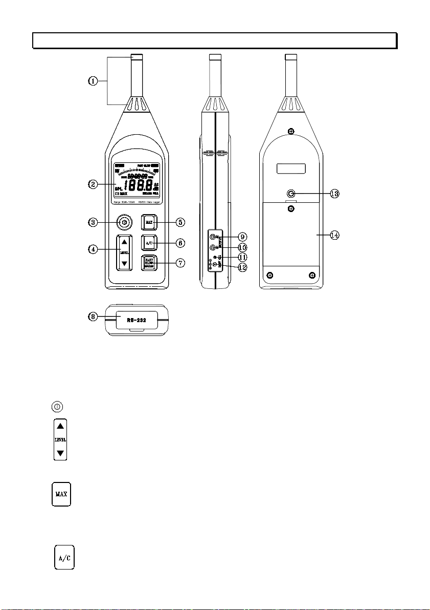
5. CONTROLS AND FUNCTIONS
1. Microphone :
Electret Condenser microphone
2.Display: The LCD shows the sound level as a numeric value and a bar graph. The
display also shows the operation mode of the instrument, the selected measurement
parameters, warning indications and real-time clock/calendar.
3. Button: Press to turn the instrument on and off.
4. Button: cLevel range buttons: select the level range for the measurement.
The following five settings are available: 30 to 90dB, 40 to 100dB,
50 to 110dB, 60 to 120dB, 70 to 130dB.
dPress these buttons to increment or decrement setting values.
5. Button: Used for reading the maximum time-weighted sound level
encountered during a measurement.
Press this button to enter maximum recording mode. The “MAX”
indicator will appear on the display. Press again to exit maximum
recording mode.
6. Button: Sets the frequency weighting to A or C mode.

7
7. Button: cSets the time weighting to FAST or SLOW mode.
FAST: uses a 125ms time-constant. This setting is used in most
situations.
SLOW: uses a 1s time constant, which smoothes out fluctuating
levels.
dData record mode: Press and hold this button for 3 seconds to
enter data recording mode. The “RECORD”
indicator will appear on the display and will
flash to indicate recording is in progress. To exit
data recording mode, press and hold for 3
seconds until the instrument returns to normal
mode and the “RECORD” indicator disappears.
eErase all records: Turn off the instrument, press and hold down this
button then turn on the instrument until the “CLr
RECORD” indication appears on the display.
8. I/O connector: RS232 input/output connector for input of control signals and output
of measurement data.
9. AC output socket: AC output signal with frequency weighting.
10. DC output socket: DC output signal corresponding to sound level.
11. CAL potentiometer: Calibration potentiometer for level adjustment.
12. External DC power supply socket: Type 1.3 coaxial power connector; centre
negative, nominal 6V DC.
13. Tripod mounting: ¼” - 20 UNC Female thread.
14. Battery cover.

8
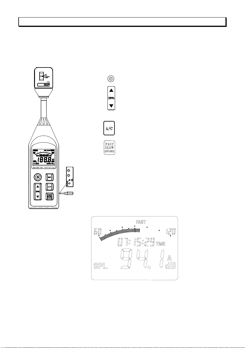
6. DISPLAY DESCRIPTION
1. Sound level range indicator (5 ranges): 30–90dB, 40–100dB, 50–110dB, 60–120dB
and 70–130dB
2. Bar graph shows the current sound level (1dB resolution).
3. Current date/time and maximum SPL measurement time.
This indicator shows the “year - month - day” or “hour: minute: second”.
4. DATE: Current date (year – month – day).
5. SPL: Current time-weighted sound level reading “Sound Pressure Level”
6. Low-battery indication
7. MAX: Maximum time-weighted sound level reading.
8. RECORD: Data records indicator
9. Sound level reading (0.1dB resolution): 30.0 – 130.0dB
10. FULL: Data records full indicator
11. dB: Sound level unit
12. A, C: “A” Frequency weighting or “C” Frequency weighting indicator.
13. TIME: Current time (hour: minute: second)
14. OVER: Over-range indicator.
15. SLOW: “Slow” time weighting indicator
16. FAST: “Fast” time weighting indicator
17. UNDER: Under-range indicator.

9
7. PREPARATION FOR USE
Power Supply
The instrument can be powered by internal batteries, or for extended operation by an
optional external 6V DC supply such as a suitableAC mains adapter or battery pack.
Rechargeable batteries may be used in the instrument, but cannot be recharged when
fitted as the instrument is not designed to recharge batteries.
Before inserting or replacing the batteries and before connecting the AC adaptor, be
sure to turn the instrument off.
1. Battery Installation
When the low battery indication symbol “ ” appears on the display, there is
insufficient power to make accurate measurements and the batteries must be
replaced.
cBefore replacing the batteries, press the button to turn off the instrument.
dUse a screwdriver to loosen the screw in the battery cover. Remove the cover
from the battery compartment. Retain the screw and cover.
eObserving correct polarity as indicated in the compartment, insert four batteries
of the type given in section 4. “Specifications”.
fRefit the battery cover and screw. Use a screwdriver to tighten the screw.
gPress the button to turn on the instrument and check for correct operation.
Note: Take care not to reverse the (+) and (-) polarity when inserting the batteries,
otherwise the instrument may be damaged.
Always replace all four batteries at the same time.
Do not mix old and new batteries or batteries of different types.
Remove the batteries from the instrument if it is not to be used for a month or
longer.
2. Using an external power source.
Insert the plug of the AC adaptor or external battery pack into the DC 6V (DC source
from 5V to 12V) socket on the side of the instrument. When a connector is inserted
into this socket, the internal batteries will be disconnected and the instrument will be
powered from the external source. The low battery symbol “ ” will appear on the
display if the external voltage is insufficient for the instrument to provide accurate
measurements.
Note: Ensure the external power source is connected with the polarity as indicated
in the following diagram, otherwise damage may be caused to the instrument and
external power source.

10
3. Windscreen
When making measurements outdoors in strong winds or when measuring air
conditioning equipment or similar, wind noise and strong air movements at the
microphone can cause measurement errors. Such effect can be reduced by using
the windscreen.
Windscreen
4. Tripod Mounting
For long-term measurements, the instrument may be mounted on a standard
camera tripod using the integral ¼” x 20 UNC mounting thread.
Tripod mounting thread
11
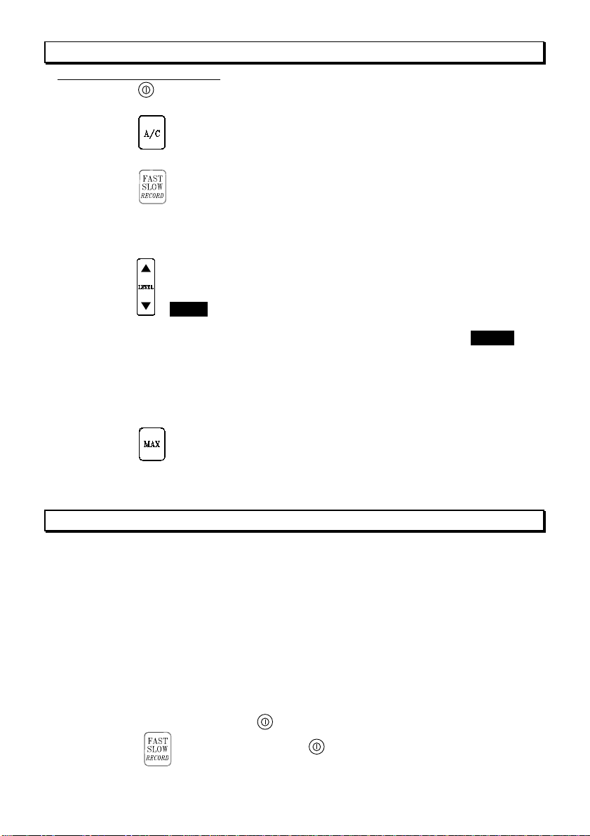
8. CALIBRATION PROCEDURE
Most national standards recommend that you calibrate your sound level meter before
each set of measurements and check the calibration after each set.
The procedure to check/adjust the displayed sound level in response to sound
calibrator :
1. Turn off the sound calibrator.
2. Press the button to turn on the instrument.
3. Use the “ ” buttons to select the 60 to 120dB reference
sound level range.
4. Use the button to select “A” frequency weighting.
5. Use the button to select “FAST” time weighting.
6. Insert the microphone very carefully and slowly all the way
into the sound calibrator coupling orifice.
7. Switch on the 1000Hz sound calibrator in its nominal 94 dB
level setting.
8. Adjust the CAL potentiometer of the instrument, until the
display reading for diffuse field is the same as the certified
pressure level of the calibrator, or is 0.1 dB higher than this
pressure level for free-field. This applies to calibrators.
9. Set the power switch of the sound calibrator to OFF.
10. Remove the microphone very carefully and slowly from the
coupler.
12
9. MEASUREMENT PROCEDURE
Sound level measurement
1. Press the button to turn on the instrument. The initial state depends on the
condition the instrument was in before it was last turned off.
2. Press the button to select the desired frequency weighting. For normal sound
level measurements, select the “A” setting.
3. Press the button to select the desired time weighting (dynamic
characteristics). Normally, the “FAST” setting should be used.
4. When performing measurement according to IEC or other standards, the frequency
weighting and time weighting setting required by the standard should be selected.
5. Press the buttons to select desired level range. Choose a setting in which the bar
graph indication registers approximately the middle of the range. If the
“ OVER ” indicator appear during measurement, the upper limit of the
selected range has been exceeded. Increase the range setting until the
symbol remains off during measurement. Similarly, if the “ UNDER ”
indicator appears, reduce the range setting until the symbol remains off
during measurement. Both indicators are non-latching and will clear
when the correct range is selected.
6. The numeric level indication shows the currently measured sound level. The
reading is updated once every second.
7. Press the button to record the maximum time-weighted sound level
encountered during a measurement period; the “MAX” indicator will appear on the
display. Press this button again to exit this mode.
10. STORE/ERASE RECORDED DATA
The instrument incorporates a memory which can be used to store measurement data.
The maximum has a data capacity of 32000 readings which can be split into 255 blocks of
records.
1. To record data, press and hold the “RECORD” button for 3 seconds to enter data recording
mode. The “RECORD” indicator will appear on the display and will flash to indicate
recording is in progress. To exit data recording mode, press and hold for 3 seconds until the
instrument returns to normal mode and the “RECORD” indicator disappears.
2. When the memory is filled (32000 data or 255 blocks is full used), the “RECORD
FULL” symbol will appear on the display.
3. The recorded data can only be reviewed after it has been downloaded to a PC.
Recorded data cannot be displayed on the instrument.
4. To erase stored data, press the button to turn the instrument off. Press and hold
down the “ ” button, then press the button to turn the instrument on. “CLr
RECORD” will appear on the display and all stored data will be erased.

13
11. OUTPUT CONNECTORS
AC Output:
An AC signal corresponding to the frequency-weighted signal is available at this
connector.
Output voltage: 1Vrms±100mVrms (scale upper limit)
Output impedance: approx. 5kΩ
Load impedance:≧1MΩ
The output voltage when the instrument is in calibration mode
(-6dB from scale upper limit, 1000Hz sine wave) is 0.5Vrms.
DC Output:
A level-converted DC signal generated by RMS detection and logarithmic
compression is available at this connector. The signal reflects the frequency and time
weighting settings of the instrument.
Output voltage: 10mV±0.1mV/dB
Output impedance: approx. 5kΩ
Load impedance:≧1MΩ
The output voltage when the instrument is reading 94dB is nominally 0.94V DC.
12. RS-232 INTERFACE, SOFTWARE INSTALLATION AND OPERATION
For the detailed instruction, please refer to the content of attached CD-ROM, which
has the complete instruction of RS-232 interface, software operation and relevant
information.
RS-232 protocol : are enclosed within the content of CD-ROM, please open the
CD-ROM for details.

TES
ELECTRICAL
ELECTRONIC
CORP.
7F, No. 31, Lane 513, Rui Guang Road, Neihu Dist. Taipei.
Taiwan, R. O. C.
Tel : (02) 2799-3660 Fax : 886-2-2799-5099
May-2009-1
Table of contents
Other TES Measuring Instrument manuals


Popular Measuring Instrument manuals by other brands


Extech Instruments
Extech Instruments SL10 user guide

Kusam-meco
Kusam-meco 288SVD instruction manual

PCB Piezotronics
PCB Piezotronics ICP 350C24 Installation and operating manual

LaserLiner
LaserLiner DistanceMaster Compact operating instructions

ATAGO
ATAGO PAL-15S instruction manual

Rohde & Schwarz
Rohde & Schwarz R&S NGU201 user manual


