TES TES-1304 User manual
TYPE - K.J.E.T.
PRINTING THERMOMETER
TES -
1304
INSTRUCTION MANUAL
TES ELECTRICAL ELECTRONIC CORP.

CONTENTS
Title Page
I. SAFETY INFORMATION ......................................................... 1
II. SPECIFICATIONS ................................................................... 2
2-1 General Information
.............................................................. 2
2-2 Electrical Specifications
....................................................... 4
III. NAME OF PARTS AND POSITION........................................ 5
IV. PRECAUTIONS AND PREPARATIONS FOR MEASUREMENT.. 10
V. OPERATIONAL GUIDE ......................................................... 11
VI. HOW TO SETUP INTERVAL PRINT.................................... 18
VII. BATTERY REPALCEMENT ................................................. 19
VIII. OPTIONAL ACCESSORY .................................................... 20
1
I. SAFETY INFORMATION
Read the following safety information carefully before attempting to
operate or service the meter.
Use the meter only as specified in this manual; otherwise, the
protection provided by the meter may be impaired.
Caution when working with voltages above 60V
DC
or 24V
AC
RMS.
Such voltages pose a shock hazard.
Environment conditions
Altitude up to 2000 meters
Indoor use only
Relatively humidity 90% max.
Operation Temperature 0
〜
50
℃
(32
℉
〜
122
℉
)
Maintenance & Clearing
Repairs or servicing not covered in this manual should only be
performed by qualified personnel.
Periodically wipe the case with a dry cloth. Do not use abrasives
or solvents on this instruments.
Do not use abrasives or solvents on this instruments.
Safety symbols
Meter is protected throughout by double insulation or
reinforced insulation.
When servicing, use only specified replacement parts.
Comply with EMC
2
II. SPECIFICATIONS
2-1 General Information
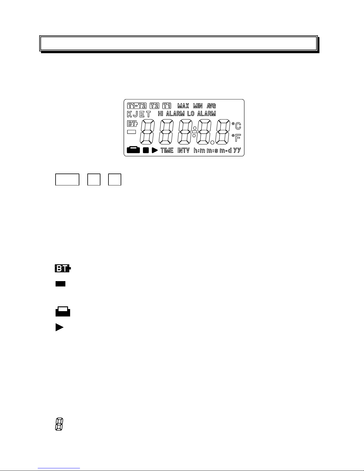
Display
:
4 1/2 LCD.
LCD Annunciator
:
Fig-1
T1-T2 , T2 , T1
:
Indicating function at channel
.
MAX, MIN, AVG :
Maximum or Minimum or Average of reading
Average=1/2(Previous reading+Current reading)
KJET
:
Type K,J,E,T thermocouple.
HI ALARM :
Over high temp point.
LO ALARM :
Under/Equal Low temp point.
:
Low battery symbol.
:
Negative polarity; No symbol for positive polarity
℃
,
℉
:
Celsius unit or Fahrenheit.
:
Printer action symbol.
,
■
:
Interval printing Start symbol/Stop symbol.
TIME
:
Calendar time.
INTV :
Interval printing symbol.
h:m :
Hour : Minute symbol.
m:s :
Minute: Second symbol.
m-d :
Month – Day symbol.
yy :
Symbol year
:
Seven segments for decimal count

3
Over Range Indication
:
or
-
appears.
Low Battery Indication
:
shows up when the battery’s voltage below the operating
voltage.
Sampling Rate
:
about 1 time per second
Power Requirement
:
6pcs 1.5V size AAA alkaline batteries or 9V DC Adaptor /500mA
minimum.
Battery Life (typ.)
:
Approx.
30 hours. ( interval printing = 60 minutes, excluding
beeper)
70 hours ( without printing & beeper)
Input protection
:
60Vdc/24Vrms
Operating Temperature and Humidity
:
0
℃
to 50
℃
( 32
℉
to 122
℉
) below 90% RH
Storage Temperature and Humidity
:
-10
℃
to 60
℃
( 14
℉
to 140
℉
) below 70% RH
Dimensions
:
193 (L)
×
74 (W)
×
37(H) mm
Weight
:
Approx. 365g with batteries & thermo-paper.
Accessories
:
Caring case, Instruction manual, Batteries, 2 Rolls of thermo-paper,
Alarm (OVER, UNDER) MINI DIN cable, type K probe.

4
Printer
:
Thermo-printing type with 16 characters per line using 38mm width
plain thermo-paper.
Instant printing : press-on printing anytime with 2 line of printing.
Interval printing
:
range from 00:00:03 to 23:59:59,
according to
interval time, continuous printing, can be set in two
ways, stopped in three ways.
2-2 Electrical Specifications
Accuracy at 23℃± 5℃, below 80%RH
Type K: ±( 0.01% rdg + 0.5℃) ( 0〜982℃)
±( 0.05% rdg + 0.5℃) ( 982〜1333℃)
±( 0.01% rdg + 0.9℉) ( 32〜1800℉)
±( 0.05% rdg + 0.9℉) (1800〜2431℉)
Type J : ±( 0.01% rdg + 0.5℃) ( 0〜760℃)
±( 0.01% rdg + 0.9℉) ( 32〜1400℉)
Type E: ±( 0.01% rdg + 0.5℃) ( 0〜703℃)
±( 0.01% rdg + 0.9℉) ( 32〜1297℉)
Type T: ±( 0.01% rdg + 0.5℃) ( 0〜400℃)
±( 0.01% rdg + 0.9℉) ( 32〜752℉)
Type K/J/E/T: ±( 0.5% rdg + 0.7℃) ( -200〜0℃)
±( 0.5% rdg + 1.4℉) ( -328 〜32℉)
Resolution:0.1℃/0.1℉
Temperature Coefficient:
0.1 times the applicable accuracy specification per ℃from 0℃to 18℃
and 28℃to 50℃( 32℉to 64℉and 82℉to 122℉)
Measurement Range:
Type K: -200 〜1333℃( -328〜2431℉)
Type J: -200 〜760℃( -328〜1400℉)
Type E: -200 〜703℃( -328〜1297℉)
Type T: -200 〜400℃( -328〜752℉)

5
III. NAME OF PARTS AND POSITION
Fig-2
1. LCD
:
Measured values, unit ,symbols, and decimal points are displayed.
2. POWER
:
Button for power on/off
3. UNIT
:
Button for exchanging temperature unit
℃
and
℉
.

6
4. PRINT
:
Button for start printing currently. The format as below:
LINE 1
1 0 : 5 1 : 1 2 1 1 - 0 2
LINE 2
T 1 K - 0 0 2 3 . 0 C
Line 1 printing time hour: minute: second, month- day, line 2 printing
measuring channel, type, value and unit.
Stop interval printing at any time and printer will print current
data.
Press this button for 2 seconds, the printer will be set to interval
printing status, and won’t stop unless this button is pressed again
or FEED button is pressed.
5. 9V-ADAPTOR SOCKET (3.5
φ
)
6. FEED PAPER (Fig-3) :
Button for moving forward thermo-paper one
line.
Perform force stop printing, and skip any
printing data.
7. TIME
:
Button for calendar.
8. MAX / MIN / AVG
:
Button for circularly selecting maximum, minimum
and average of reading on measuring channel T
1
/T
2
/T
1
-T
2
.
Fig-3

7
9. Hi/ Low Alarm output connector
:
Fig-4
Pin 1: GND ( external supply low voltage )
Pin 2: VCC ( external supply high voltage )
Pin 3: SYNC( external trigger signal )
Pin4 (HiAlarm) and pin5 (LowAlarm) signals have to be
synchronized with pin3. The pin5 and pin4 will not function
(always low) unless SYNC (pin3) is in the high state. If SYNC
is a low signal, then pin4 and pin5 will be in the low state.
Pin4
1
: HiAlarm
If the reading is higher than the high alarm point, then (pin 4)
will be in high state, otherwise, in Low state.
Pin 5
1
: LoAlarm
If the reading is lower than / equal the low alarm point, (pin 5)
will be in high state, otherwise, in low state.
1
The output of Pin 4 and 5 might delay 0.4 sec due to the A/D
scanning time in the data logger.
Description of the MINI DIN cable:
Red wire : VCC (external supply high voltage)
Black wire : GND (external supply low voltage)
Yellow : SYNC (external trigger signal)
White : HiAlarm
Purple : LowAlarm

8
Note: voltage VCC to GND is 16V Maximum, 5V Minimum.
GND
≦
SYNC
≦
VCC
Example :
Hi Alarm= 1300.5
℃ ,
Lo Alarm= -50.5
℃
If LCD reading
≧
1300.5
℃
Result : Hi Alarm output reading approx 5V
Lo Alarm output reading approx 0V
If LCD reading
≦
-50.5
℃
Result : Lo Alarm output reading approx 5V
Hi Alarm output reading approx 0V
Example :
Hi alarm= 25.5
℃ ,
Lo alarm= 25.5
℃
If LCD reading = 25.5
℃
Result : Hi Alarm output reading approx 5V
Lo Alarm output reading approx 5V

9
10. T
1
/T
2
/T
1
-T
2
measuring :
Button for select display methods, T
1,
T
2,
T
1
-T
2
, cycle and normal cycle
mode means it will perform T
1,
T
2,
T
1
-T
2
measuring circularly.
11. MENU
:
Button for start/stop set-up parameters mode.
The value will be increased much fast if user do not release the key.
12. UP
:
Button for increasing the value of parameters, increasing the
parameter rapid.
13. RIGHT
:
Button for moving to the desired parameter.
14. DOWN
:
Button for decreasing the value of parameters.
15. LEFT
:
Button for moving to the desired parameter.
Parameters (in sequence):
K/J/E/T (type of thermocouple)
00/01 (interval printing enable or disable)
℃
/
℉
(high/ low alarm temperature unit)
Hi/Lo Alarm (high/low alarm point ranging from measure highest and
measure lowest of temp type.)
Ex: K Type (1333.3 ~ -200.0
℃
)
J
Type ( 760.5 ~ -200.0
℃
)
INTV (printing interval ranging from 00h:00m:03s to 23h:59m:59s)
Interval printing start / stop time (ranging from 00h:00m to 23h:59m)
Calendar year (ranging from 1900 to 2999 year)
Calendar month-day (ranging from 01-01 to 12-31)
Calendar hour-minute (ranging from 00h:00m to 23h:59m)
Calendar minute-second (ranging from 00m:00s to 59m:59s)
16. Way out for thermo-paper.
17. Temperature probe sockets.
18. Battery cabinet and cover
:
6 pcs 1.5V size AAA alkaline batteries.

10
IV. PRECAUTIONS AND PREPARATIONS FOR
MEASUREMENT
1. Before getting use of this instrument, examine it to make sure no
shipping damage occurring. Otherwise notify your dealer.
2. Save all packing materials until you are sure that this unit can
normally operate.
3. Be sure that batteries are correctly placed in the case or adaptive 9V
Adaptor is in correct connection.
4. An unsecured battery cover will cause error measuring.
5. To avoid battery leakage problem, remove batteries if this meter will
not be used for a long time.
6. Do not use or store this meter outside the opearting / storage
enuiorment.

11
V. OPERATIONAL GUIDE
A. This meter can be supplied with batteries or 9V Adaptor, If using
batteries :
Remove the rear cover, and install batteries, pay attention to the
polarity of battery socket. If using 9V Adaptor, make sure that it is in
good connection to the Adaptor socket of the meter. Choose the right
temperature probe for your application and insert it into the tempture
probe socket.
B. Press the button to power on the meter. If “ ” appears, it
indicates no temperature probe or the probe is broken. To enter test
model before, a version number. After the power is on, before
entering measureing mode, “16” will be shown on LCD.
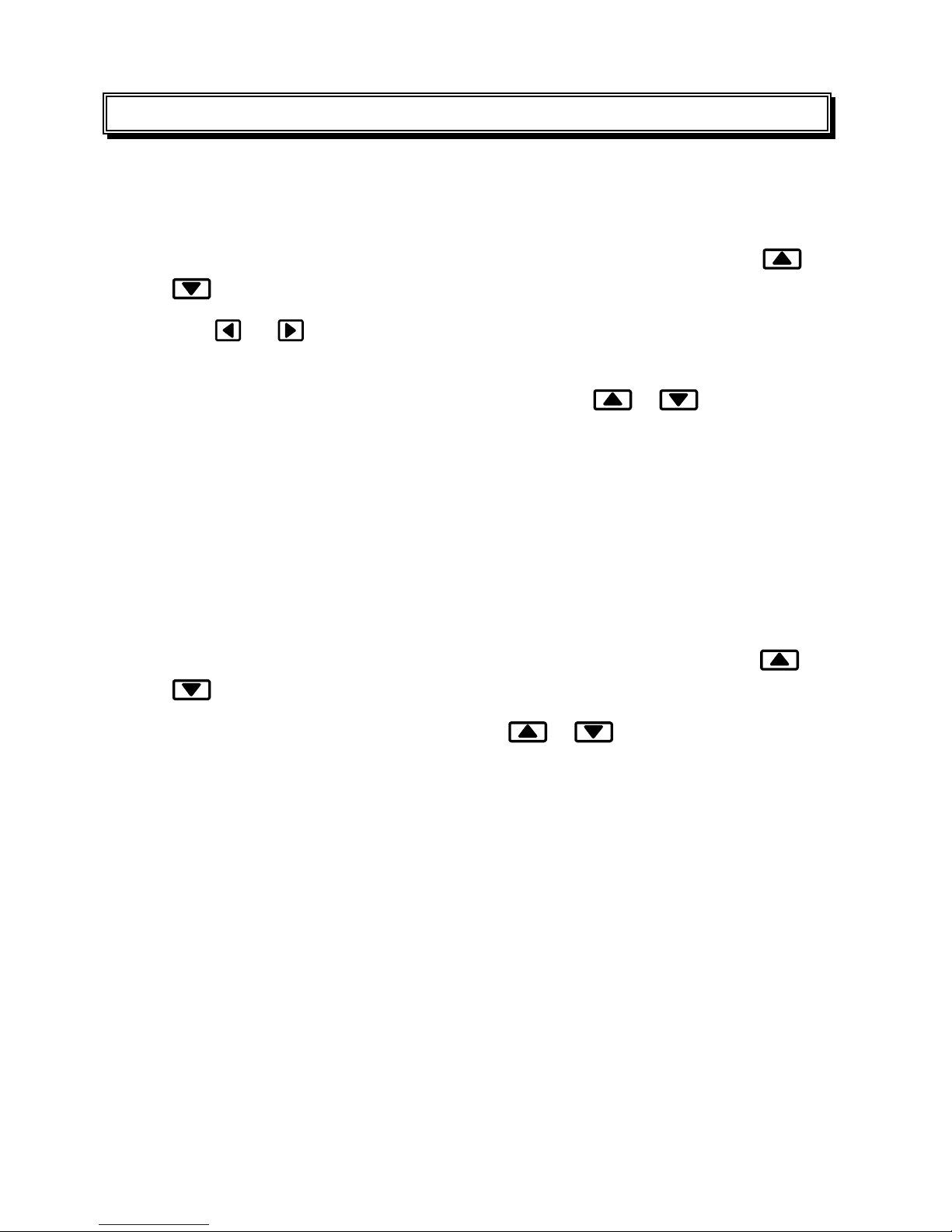
C. To start the parameter setting, press “
MENU
” button, to stop, press it
again. Press left and right switch (
or button ) to select the
type of parameter; up and down switch (
or button ) to
increase or decrease the value of parameters. When modifing
parameters, the symbol will flick.
The parameter in detail sequence:
1. INTERVAL PRINTING STATUS (01/ENABLE, 00/DISABLE):
LCD displays as Fig-5
Fig-5
2. TYPE OF THERMOMETER (K/J/E/T) : LCD displays as Fig-6
Fig-6

12
3. ALARM UNIT (
℃
/
℉
):LCD displays as Fig-7
Fig-7
4. FIRST THREE DIGITS IN HI ALARM (-399
〜
399):
LCD displays as Fig-8
Fig-8
5. LAST TWO DIGITS IN HI ALARM (00
〜
99):
LCD displays as Fig-9
Fig-9
6. FIRST THREE DIGITS IN LO ALARM (-399
〜
399):
LCD displays as Fig-10
Fig-10
7. LAST TWO DIGITS IN LO ALARM (00
〜
99):
LCD displays as Fig-11
Fig-11
Example :
Hi Alarm = 1234.5
℃
Example :
Lo Alarm = -50.8
℃

13
8. HOUR OF INTERVAL PRINTING (00
〜
23):
LCD displays as Fig-12
Fig-12
9. MINUTE OF INTERVAL PRINTING (00
〜
59):
LCD displays as Fig-13
Fig-13
10. SECOND OF INTERVAL PRINTING (00
〜
59):
LCD displays as Fig-14
Fig-14
11. HOUR OF START INTERVAL PRINTING TIME (00
〜
23):
LCD displays as Fig-15
Fig-15
12. MNUTE OF START INTERVAL PRINTING TIME(00〜59):
LCD displays as Fig-16
Fig-16
※
NOTE : Start print time must less than stop print time.

14
13. HOUR OF STOP INTERVAL PRINTING TIME (00
〜
23) : LCD
displays as Fig-17
Fig-17
14.
MINUTE OF STOP INTERVAL PRINTING TIME (00
〜
59):
LCD displays as Fig-18
Fig-18
15. FIRST TWO DIGITS OF CALENDAR YEAR (19
〜
29):
LCD displays as Fig-19
Fig-19
16. LAST TWO DIGITS OF CALENDAR YEAR (00
〜
99):
LCD displays as Fig-20
Fig-20
17. MONTH DIGITS OF CALENDAR MONTH-DAY (01
〜
12):
LCD displays as Fig-21
Fig-21

15
18. DAY DIGITS OF CALENDAR MONTH-DAY (01
〜
31):
LCD displays as Fig-22
Fig-22
19. HOUR DIGITS OF CALENDAR HOUR-MINUTE (00
〜
23):
LCD displays as Fig-23
Fig-23
20. MINUTE DIGITS OF CALENDAR HOUR-MINUTE (00
〜
59):
LCD displays as Fig-24
Fig-24
21. SECOND DIGITS OF CALENDAR MINUTE-SECOND (00
〜
59) :
LCD displays as Fig-25
Fig-25

16
If interval printing is enabled by setup parameters, then the printer will
action as below :
11
:
54
:
00 11-02
INTV
:
00
:
00
:
10
First two lines:
Line1: hour:minute:second month-day (start printing time)
Line2: interval printing time hour:minute:second
Following two lines:
Line1: hour:minute:second month-day (interval printing time)
Line2: measuring channel, type, value and unit.
Last two lines:
Line1: hour:minute:second month-day (stop pointing time)
Line2: interval printing time hour:minute:second
※
NOTE : If print button is pressed during this period, then the last two
lines won’t be printed.

17
If print button is hold for 2 seconds, it will perform as the following :
12
:
58
:
18 11-02
INTV
:
00
:
00
:
10
12
:
58
:
28 11-02
T1 K
–
0039.5
℃
12
:
58
:
38 11-02
T1 K
–
0L.
℃
12
:
58
:
48 11-02
T1 K
–
0L.
℃
12
:
58
:
58 11-02
T1 K
–
0035.2
℃
12
:
59
:
08 11-02
T1 K
–
0L.
℃
12
:
59
:
18 11-02
T1 K
–
0037.0
℃
12
:
59
:
20 11-02
T1 K
–
0L.
℃
First two lines:
Line1: hour:minute:second month-day
Line2: interval printing time hour:minute:second
Following lines:
Line1: hour:minute:second month-dat (interval printing time)
Line2: function test channel, type and reading with polarity,
decimal point and unit.
To stop printing, press PRINT button, or FEED button if FEED button is
pressed, skip printing if PRINT button is pressed last two lines data.
Thermo-paper prints approx 650 datas.
18
VI. HOW TO SETUP INTERVAL PRINT
1. Setup interval print with 24 hours limitation.
Entering menu mode by pressing MENU button.
Enable interval print bit as described in page 11 fig-5 by pressing
/
button.
Use
/
to change menu function to interval print function as
described in page 13 fig-12.
Setup Interval/Start/Stop print time by pressing
/ button as
described in Page 13, 14, Fig-12 to fig-18, note that the start print time
must less than the stop print time in this mode.
Press MENU again to enter normal function. The INTV symbol will be
shown on LCD.
2. Setup interval print without 24 hours limitation.
Entering Menu mode by pressing MENU button.
Disable Interval Print bit as described in page 11 fig-5 by pressing
/
button.
Setup Interval Print Time by pressing
/ button as page 13, fig-
12 to fig-14.
Press MENU again to enter normal function.
Press and hold PRINT button for about 3 second, the INTV symbol will
be shown on LCD.
3. During the Interval Print period, no button can be available except PRINT
and FEED button. When the PRINT button has been pressed, one more
line be printed, and the printing function will be stoped at once when the
FEED button has been pressed.
Table of contents
Other TES Measuring Instrument manuals


