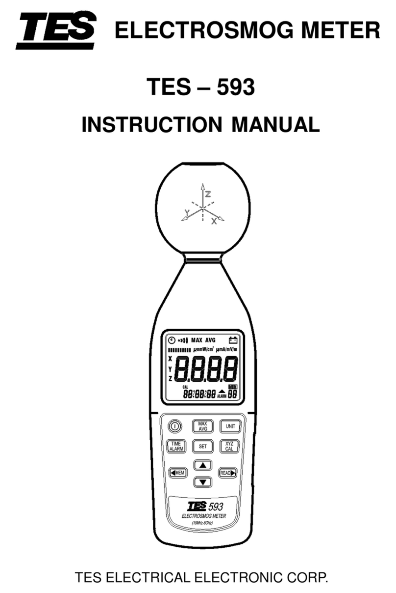
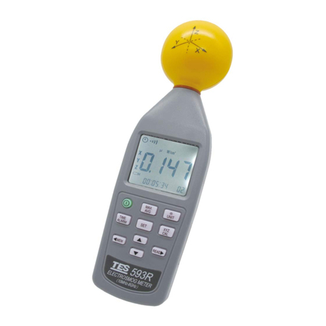
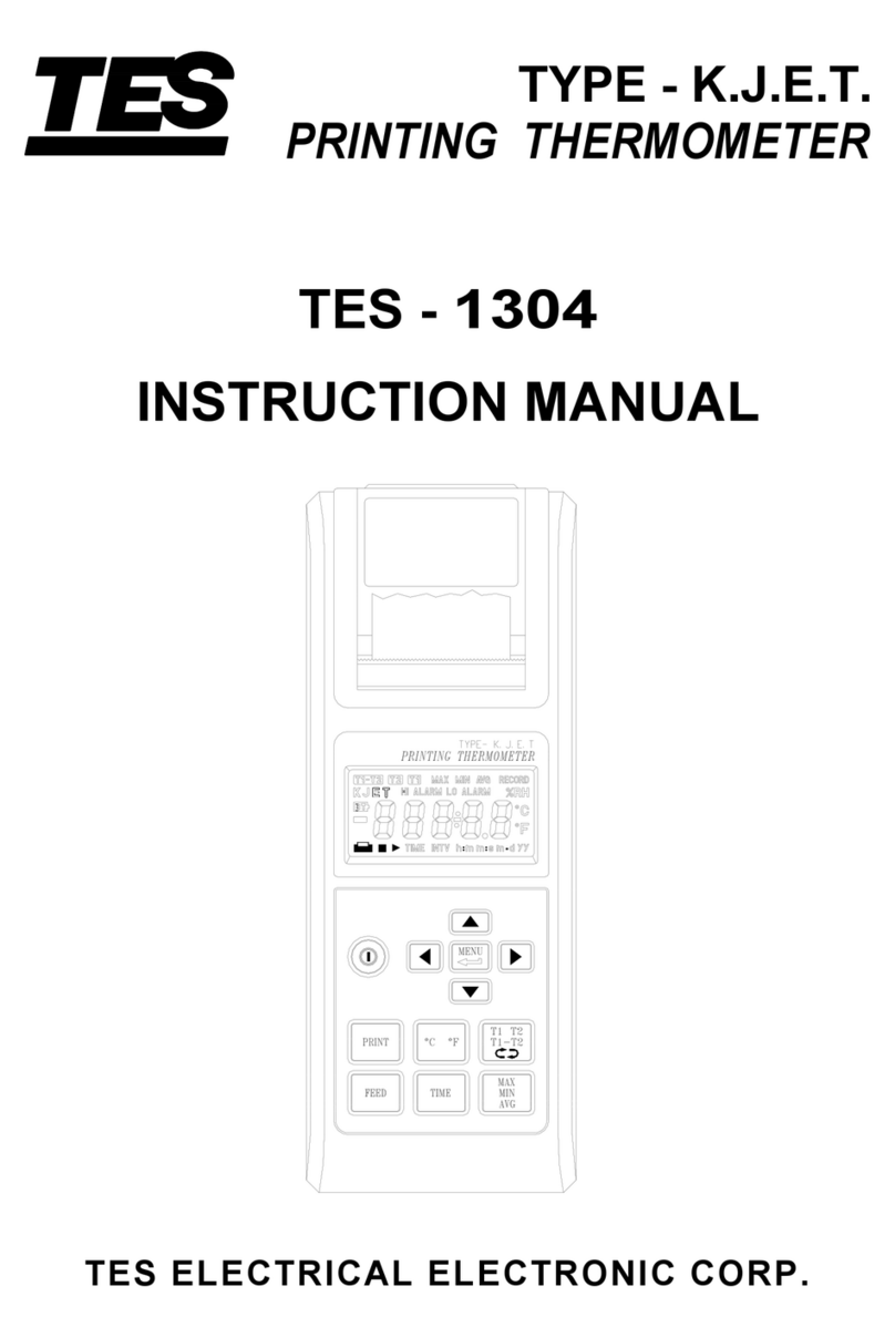
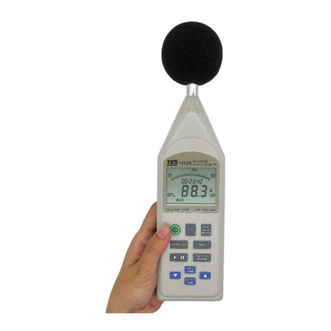
TES TES-133 User manual

Luminous Flux Meter
TES-133
INSTRUCTION
MANUAL
※
※※
※
Enclosed CD : Software & Protocol Inside.
133
ZERO RATIO
AVG
MAX MIN
ZERO
TES ELECTRICAL ELECTRONIC CORP.

CONTENTS
Title Page
1. INTRODUCTION ..............................................................................1
2. FEATURES.......................................................................................2
3. SPECIFICATIONS............................................................................2
4. PARTS & CONTROLS.....................................................................4
4-1 Description of Parts & Control keys............................................4
4-2 Description of Display.................................................................8
5. OPERATING INSTRUCTIONS.......................................................10
5-1 Setting the Calibration Factor...................................................10
5-2 luminous Flux Measurement ....................................................11
5-3 Maximum & Minimum Recording Measurement ......................12
5-4 Hold Function Operation...........................................................12
5-5 Zero Iunction Operation............................................................13
5-6 Ratio Function Operation..........................................................13
5-7 ZERO-Ratio Function Operation ..............................................15
5-8 Ratio – ZERO Function Operation............................................15
5-9 Sort Function Operation............................................................16
5-10 Comparator Setting and Operation.........................................17
5-11 Manual Data Memory and Read Mode...................................18
5-12 Auto Datalogging Function......................................................19
5-13 RS232 Communication...........................................................20
5-14 To Disable Auto Power off Function.......................................21
6. BATTERY CHECK-UP &
&&
&REPLACEMENT..................................21
7. SPECTRAL SENSITIVITY CHARACTERISTIC.............................21
8. MAINTENANCE..............................................................................22
9. RS-232 INTERFACE, SOFTWARE INSTALLATION AND
OPERATION...................................................................................22
※
※※
※
Copyright ©
2009 TES Electrical Electronic Corp. All rights reserved.

1
1. INTRODUCTION
The meter is an easy-to-use, precision photometric meter
designed for use in the field, laboratory, or production floor. The
meter measures luminous flux from source such as LED’s, small
lamps, and fibre-illuminators. The meter features a 75mm
diameter integrating shpere that collects the total light entering
the sphere measurement port.
The integrating is the ideal optical device for measuring luminous
flux from a source placed inside the sphere or just outside the
sphere sample port.
It meets CIE photopic spectral response, f ’
1
≦6%.
The meter is compact, tough and easy to handle owing to its
construction.
The light sensitive component used in the meter is a very
stable, long-life silicone photo diode and spectral response filter.
Measure LED’s, small lamps, and fibre-illuminators.
Measure narrowband and broadband sources.
Measure highly divergent sources.
Reduced sensitivity to light source alignment.
Reduced sensitivity to polarization.
Omits error introduced from detector area non-uniformities.
U.S. Pat. No. Des. 446,135
Taiwan Pat. No. M 342502

2
2. FEATURES
Easy-to-read 4 digit LCD display.
Spectral Sensitivity close to CIE photopic Curve.
Measuring Level Range: 0.05 to 7000 lumens, Autoranging 4 steps.
Accurate and Instant response.
Data Hold function.
Auto Data Hold function.
Data memory and read function.
Maximum / Minimum function.
Zero function.
Ratio function.
Sort function.
Comparator function.
Auto power off function.
Auto datalogging & RS-232 interface.
3. SPECIFICATIONS
•Display :4 digit LCD reading.
•Measuring Range : 9.999, 99.99, 999.9, 7000 lumens
(Autoranging 4 steps)
•Resolution : 0.05 – 9.999 0.001 lumen
10.00 – 99.99 0.01 lumen
100.0 – 999.9 0.1 lumen
1000 – 7000 1.0 lumen
•Accuracy:0.05 to 0.1 ±7%, 0.1 to 1000 ±2%, 1000 to 7000 ±3%
•Overange Display : LCD will show “OL” symbol.
•Spectral Response : CIE Photopic.
(CIE human eye response curve).

3
•Spectral Accuracy : CIE Vλfunction f ’
1
≦6%
•Integrating Sphere : Diameter : 75 mm
Material : BaSO
4
Sample Port : 25 mm dia.
•Photo Detector : One silicone photo diode and spectral response
filter.
•Temperature Characteristics :±0.1% / ºC.
•Sampling Rate : 5 times/sec.
•Manual Data Memory Capacity :999 sets.
•Auto Datalogging Capacity : 38000 sets.
•Operating Temperature & Humidity:
0ºC to 50ºC(32ºF to 122ºF)& 0% to 80% RH.
•Storage Temperature and Humidity:
-10ºC to 60ºC(14ºF to 140ºF)& 0% to 70% RH.
•Power Source :6 pcs size AAA battery.
•Battery life ( typical ) : 100 hours ( carbon zinc ).
•Integrating Shpere Lead Length : 80 cm ( approx. ).
•Integrating Shpere Dimensions : 94(D) ×108(H) mm
•Meter Dimensions : 150L×72W×35H (mm);
•Weight :470g .
•Accessories :Carrying case, instruction manual, batteries,
software CD rom & RS232 cable, Port Adaptor kit.

4
4. PARTS & CONTROLS
4-1 Description of Parts & Control keys
17
13
133
15
1
2
3
5
6
14
8
11
10
12
9
7
4
ZERO RATIO
18
16
AVGMAX MIN
ZERO
1. LCD Display :4 digit display with a maximum of 9999 readings
and the indicating signs of measured values, unit function symbols
and decimal points etc. are displayed.
2. Power Control key:The power switch key turns the meter
ON or OFF.
3. key :
1Press key to display the Maximum (MAX), Minmum
(MIN) and Current (MAX MIN) measured values, press this key
for 3 seconds to exit this mode.
2In the READ mode, press key to display the manual
memorized data value of Maximum (MAX), Minimum (MIN),
and Average (AVG), if the manual memorized data all are
measured in the same mode.

5
4. Data-Hold key :
1Press key to hold data, the D-H annunciator is displayed,
press this key again to exit this mode.
2Press key for 3 seconds to enter the auto hold mode, the
A-H annunciator is displayed, press key for 3 seconds to
exit this mode.
3Press and hold down key, then press key to turn on
the meter, the auto power off function will be disabled, and the
auto power off symbol “ ” will be disappear.
5. key : Press key to enter the zero mode, the
“ZERO” annunciator is displayed, press this key again to exit
this mode.
6. key : Press key to enter the setting mode, press
key to exit this mode.
1Press key to setting the sort tolerance limits.
2Press key to setting the comparator High / Low values.
3Press key to setting the auto datalogging interval time.
4Press key to setting the calibration factor value.
5Press key to setting the reference value.
7. key : Press key to enter the ratio mode, the “RATIO”
annunciator is displayed, press this key again to exit this mode.
8. key :
1Press key to enter the sort mode, the “SORT”
annunciator is displayed, press this key again to exit this mode.

6
2Press key first then press key to enter the sort
tolerance limits setting mode.
9. key :
1Exit a setting mode or store the displayed setting.
2Exit the READ and Auto datalogging mode.
10. key :
1Press key to enter the comparator mode, the COMP
annunciator is displayed, press this key again to exit this mode.
2Press key first then press key to enter the
comparator value setting mode.
11. key :
1Press key one time to store one set LCD reading to
memory.
2Press key for 3 seconds to enter or exit auto
datalogging mode.
3In the reference value setting mode and the comprator value
setting mode, press ⊳key to move the decimal point left to the
desired position.
4Press and hold down key then press key to turn on
the meter to enter the clear manual and auto memorized data
mode.
5Press key first then press key to enter auto
datalogging interval time setting mode.
12. key :
1Press key to enter the read mode, the R annunciator is
displayed, press key to exit this mode.

7
2Press key for 3 seconds to turn on the RS232 interface.
3In the reference value setting mode and the comprator value
setting mode, press key to move the decimal point right to
the desired position.
13. key :
1In the setting mode press key to increase the setting value.
2In the READ mode press key to increase the memory
location.
3Press key first then press key to enter the
calibration factor setting mode.
14. key :
1In the setting mode pess keyto decrease the setting value.
2In the READ mode press keyto decrease the memory
location.
3Press key first then press key to enter the SORT
and RATIO reference value setting mode.
4Press key to display the reference value, press this key
again the reference value is disappeared.
15. Integrating sphere.
16. Port Adaptor kit :
2mm Adaptor size.
3mm Adaptor size – (T1)
4mm Adaptor size
5mm Adaptor size – (T1-3/4)
8mm Adaptor size
10mm Adaptor size – (T3-1/4, T3-3/4)
24mm Adaptor size
17.AC adaptor socket (9V, 100mA).
18.RS232.

8
4-2 Description of Display
RATIO
ZERO
AVG
ZERO
MINMAX
: Auto power off indication.
ZERO : Zero mode indication (φ= φ
in
–φ
d
)
ZERO RATIO : Zero – Ratio mode indication
[RATIO = (φ
in
– φ
d
)/ (φ
R
– φ
d
)]
RATIO : Ratio mode indication (RATIO = φ
in
/ φ
R
)
RATIO ZERO : Ratio – Zero mode indication
[RATIO = (φ
in
– φ
d
)/ φ
R
]
D-H : Display data hold mode indication.
A-H : Display Auto data hold mode indication.
SET : Setting mode indication.
SET SORT 10% : Sort tolerance limits setting mode indication
(10% to 100%).
SET 1.100 lumen : Comparator High limit value setting
indication.
SET 0.900 lumen : Comparator LOW limit value setting
indication.
SET INTV
.
1 A-M : Auto datalogging interval time selection
mode indication (1, 2, 3, 4, 5, 6, 7, 8, 9, 10,
20, 30, 40, 50 seconds or 1, 2, 3, 4, 5, 6, 7,
8, 9, 10, 20, 30, 40, 50, 60 minutes).

9
SET CAL 1.
: Calibration factor setting mode indication (0.01 to
9.99).
SET REF 1.
lumen : Reference value setting mode indication.
MAX : Maximum reading display.
MIN : Minimum reading display.
MAX MIN : Current reading display.
AVG : Manual data memory average value display.
COMP : Comparator function on indication.
: Over comparator high limit indication.
: Below comparator low limit indication.
lumen : luminous flux unit.
SORT 1
% : Sort tolerance limit percentage display.
CAL 1.
: Calibration factor value display (φ= φ
in
x CAL)
SORT ±
±±
±: Sort class display (-10 to +10 classes).
Each class is a tenth part of the tolerance limit.
SORT + OL : Over sort tolerance limit.
SORT – OL : Below sort tolerance limit.
: Low battery indication.
: Last manual data memory address.
M : Manual data memory indication, M appears one time store one
set data into memory.
R: Recall manual data memory address number indication, the
memory data display for read.
REF : Reference value display.
A-M : Auto datalogging indication, A-M disappears one time store
one sets data into the memory.

10
5. OPERATING INSTRUCTIONS
When press key to trun on the meter, the various settings
depend on the condition the meter was in before it was last
turned off.
5-1 Setting the Calibration Factor
Because the meter of the photopic filter is not perfect and small
adjustments to the collected radiation profile are needed to
improve the meter accuracy when measuring LED’s. These
adjustments are dependent on the peak wavelength and spectral
bandwidth of the test LED emission. The meter frimware makes
corrections to the photometric data through a user entered
calibration factors. If the test source is not an LED, the calibration
factor entry should be “1.00”.
1. Press keyto turn on the meter.
2. Press key first then press key to enter the
calibration factor setting mode.
3.Press key to set to the desired calibration factor value.
4. Press key to store the value and exit this mode.

11
5-2 luminous Flux Measurement
1. Determine an appropriate entry sample port from the port adaptor
kit.
2. Press keyto turn on the meter.
3. Position the light source at the sample port. If you are measuring
LEDs and the meter includes a port adaptor, insert the lens into
the aperture as far as it will go. If no adaptor is available, position
the LED at the sample port so the tip of the lens protudes a few
millimeters beyond the outer enclosure of the sphere.
4. Press key to store the dark current flux.
5. Energize the light source and allow ample time for warm-up.
6. Read the luminous flux value from the LCD display.
7. To freeze a measured value, press key.
8. Press key each time will store one measured value into
memory.
9. Press key first then press key to display the
manual memorized data value of Maximum (MAX), Minimum
(MIN) and Average (AVG), if the manual memorized data all are
measured in the same mode.
10. Press key to exit the READ mode.
ZERO

12
5-3 Maximum & Minimum Recording Measurement
1. Press key to enter the recording mode, the auto power off
function will be auto cancelled.
2. Press key to display the Maximum (MAX), Minimum
(MIN) and Current (MAX MIN) measured values.
3. Press this key for 3 seconds exit this mode.
MINMAX
5-4 Hold Function Operation
A. Data Hold
1. Press key to freeze an instantaneous measurement enter
to the data hold mode, the “ D-H ” annunciator is displayed.
2. Press key again to exit this mode.
B. Auto Data Hold
1. Press key for 3 seconds to enter auto data hold mode, the
A-H annunciator is blink.
2. When the measured reading is stable (±
±±
±3 digits), the meter will
auto hold the data, the “ A-H ” annunciator is fixed.
3. Press key again will repeat itself.
4. Press keyfor3seconds toexitthis mode.

13
5-5 Zero Function Operation
Used to offset a dark current reading.
1. Press key to store the dark current reading and enter the
ZERO mode, the “ZERO” annunciator is displayed.
2. All subsequent reading on the LCD are relative to the previous
reading, the LCD will read : φ= φ
in
- φ
d
Where φ
in
is the total luminous flux into the sphere at time of
measurement and φ
d
represents the dark current reading.
3. Press key again to exit this mode.
5-6 Ratio Function Operation
Used to display a ratio of flux measurement.
A. Use the current measured value as the reference value.
1. Press key to store the reference value and enter the
RATIO mode, the “RATIO” annunciator and the stored reference
value are displayed. If the user press key when the LCD
reading is 0.000 lumen, a “RATIO Err” error message will display
division by ZERO is not allowed.
2. All subsequent measurements are now displayed as the ratio of
the current measurement to the stored reference value, the LCD
will read : RATIO =
φ
φ
in
RATIO
(0<φ
in
<OL, 0<φ
RATIO
<OL)
Where φ
RATIO
is the total luminous flux into the sphere when
key is pressed.
3. Press key again to exit this mode.
ZERO
RATIO

14
B. Use the setting value as the reference value.
1.Setting the reference value.
a.Press key first then press key to enter the
reference value setting mode, the “ SET REF ” annunciator and
the previous reference value are displayed.
b.Press ⊳ keys to select the desired decimal point position.
c. Press keys to set the desired reference value.
d.Press key stored the value and exit this mode.
2. Press key to display the reference value.
3.Press keyto enter the RATIO mode, the “RATIO”
annunciator is displayed. All measurements are now displayed as
the ratio of the current measurement to the reference value, the
LCD will read : RATIO =
φ
φ
in
REF
(0<φ
in
<OL, 0<φ
REF
<OL)
Where φ
RATIO
is the reference value.
4. Press key again to exit the RATIO mode.
5. Press key again the reference value is disappeared.
RATIO

15
5-7 ZERO-Ratio Function Operation
A. Use the current measured value as the reference value.
1. Press key to store the dark current (φ
d
), and subsequently
takes a measurement (φ
in
), the LCD will read : φ= φ
in
- φ
d
2. Press key, the LCD will read : RATIO =
φ
φ
φ φ
in d
RATIO d
−
−
Where φ
RATIO
is the total luminous flux into the shpere when
key is pressed.
B. Use the current reference value.
1. Press key to display the reference value (φ
REF
).
2. Press key to store the dark current (φ
d
), and subsequently
takes a measurement (φ
in
), the LCD will read : φ= φ
in
- φ
d
3. Press key, the LCD will read : RATIO =
φ
φ
φ φ
in d
REF d
−
−
RATIO
ZERO
5-8 Ratio – ZERO Function Operation
A. Use the current measured value as the reference value.
1. Press key, the LCD will read : RATIO =
φ
φ
in
RATIO
2. Press key for the dark current φ
d
and records a
measurement, the LCD will read : RATIO =
φ
φ
φ
in d
RATIO
−

16
B. Use the current reference value
1. Press key to display the reference value (φ
REF
).
2. Press key, the LCD will read : RATIO =
φ
φ
in
REF
3. Press key, the LCD will read : RATIO =
φ
φ
φ
in d
REF
−
ZERORATIO
5-9 Sort Function Operation
A. Setting the reference value (see 5-6. B.1).
The reference value can not less than 0.100 lumen in the sort mode.
B. Setting the sort tolerance limits.
1. Press key first then press key to enter the sort
tolerance limits setting mode, the “ SET SORT ” annunciator is
displayed.
2. Press keys to set the desired tolerance limits from 10% to
100%.
3. Press key to stored the value and exit this mode.

17
C. Sort Operation
1. Press key to enter the SORT mode, the reference value
and the sort tolerance limits is displayed.
2. The sort tolerance limits is divided into ten classes from -10 to -1
and +1 to +10 classes.
If the measured value over the tolerance limits, the +OL or -OL
will be display.
Example:
If the reference valus is 0.100 lumen, the sort tolerance limits is
50%, and the measured value is 0.073 lumen, then “SORT-6” is
displayed.
3. Press key each time will store one measured value into
memory.
4. Press key first then press key to display the
manual memorized data value of Maximum (MAX), Minimum
(MIN) and Average (AVG), if the manual memorized data all are
measured in the same mode.
5. Press key to exit the READ mode.
6. Press key to exit the SORT mode.
MAX
MIN
AVG
5-10 Comparator Setting and Operation
A. Setting the comparator values
1. Press keyto turn on the meter.
2. Press key first then press key to enter the
comparator High limit value setting mode, the “ SET COMP ”
annunciator is displayed .

18
3. Press ⊳ keys to select the desired decimal point position.
4. Press keys to set the desired High limit value.
5. Press key to enter the comparator Lowlimit value setting mode.
6. Press ⊳ keys to select the desired decimal point position.
7. Press keys to set the desired Low limit value.
8.Press key to exit this mode.
B. Comparatar Operation
1. Press keyto enter the comparator mode, the “ COMP ”
annunciator is displayed.
2. If measurement value exceeds the setting value, the “” or “”
annunciator will be displayed and the beeper will sound.
3. Press keyagain to exit this mode.
5-11 Manual Data Memory and Read Mode
A. To Memorize the reading
Pressing key each time will store one set of reading into
the memory. At this moment, LCD will show the " M " mark one
time and the memory address number. Total memory size is 999
sets.
B. To Recall and Read Manual memorized reading
1. Press keyto enter the READ mode, the LCD will show " R "
mark and the memory address number.
2. Press " " or " " key to select the desired memory address
number data for display.
Table of contents
Other TES Measuring Instrument manuals
Popular Measuring Instrument manuals by other brands

Bosch
Bosch Tronic 3000T Installation manual and operating instructions
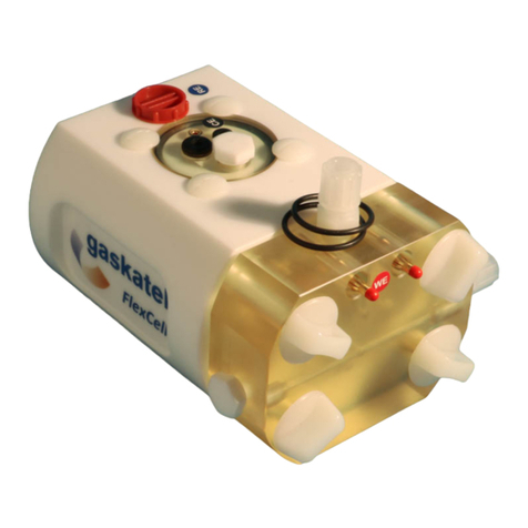
gaskatel
gaskatel FlexCell PTFE user manual
LumaSense technologies
LumaSense technologies IMPAC IGA315-K USB Operation manual
RECO
RECO CRAGG RAILCHARGER 520603-2V150 instruction manual
DH Instruments
DH Instruments PG7000 - V3.0 Operation and maintenance manual
Honeywell
Honeywell Minitrend Installation instruction
