Tescom i-com Series User manual

i-com SERIES EXTERNAL
GSM / GPRS MODEM
& BATTERY MODULE
(Model : GM-2)
(Model : GM-3)
(Model : GMB1)
USER MANUAL

1
We thank you for choosing our product for protection of your electrical device.
GSM modem accesories are designed with care. In order to user the device properly you should read all the pages of this
user’s manual.
Environment
Our products are designed and manufactured according to environmental regulations.
Does not contain CFC or HCFC
Recycling
All packaging material is choosen from recyclable material. Please, be sure to recycle all the packaging material.
• If you need to store the device, store it in a dry place.
• Storage temperature is -10 0C to +70 0C
İÇİNDEKİLER
1. INTRODUCTION…………… ........................................................................................ 2
1.1 Unpackaging ........................................................................................................... 2
1.2 General Overview ................................................................................................... 2
1.3 Functions ................................................................................................................ 3
1.4 Technical Specification ........................................................................................... 3
2. INSTALLATION ........................................................................................................ 4
2.1 MODEM – PC connection (configuration mode) ................................................... 4
2.2 MODEM – KGK connection (operation mode) ...................................................... 4
3. Modem Setup with GSM Configurator Software ................................................... 5
3.1. Setup of software ................................................................................................... 5
3.2. Usage of software .................................................................................................. 10
3.2.1 Pc Adjust tab ..................................................................................................... 10
3.2.2 Sms Adjust tab .................................................................................................. 12
3.2.3 Gprs Adjust tab ................................................................................................. 13
3.2.4 General Adjust tab ............................................................................................ 14
3.2.5 Command tab .................................................................................................... 14
4. GSM Modem Operation ......................................................................................... 15
5. GMB1 external battery unit connection (for GM-2) .............................................. 15
6. Display LEDs ........................................................................................................... 16

2
1. INTRODUCTION
1.1 Unpackaging
External GSM/GPRS Modem (GM-2 or GM-3)
9 Volt DC Power Adapter
RS232 cable for Modem - PC connection (CC01- gray cable) – for configuration
RS232 cable for UPS-Modem connection (CC05-green cable) – for regular opreration
CD containing user’s manual
1.2 General Overview
RS232 connection (for UPS connection)
SIM card socket (push-push type)
DC power adapter connection (9Vdc - 24Vdc 1A)
GM-2 GSM modem external battery unit connection
GSM antenna connection
GM-3 internal battery unit on/off switch
Display LEDs
Battery charge status LED
GM-2 Front panel
GM-2 Back panel
GM-2
GM-3
GM-3 Front panel
GM-3 Back panel
2
3
4
5
1
2
5
3
6
1
2
3
4
5
1
7
7
6
7
8
8

3
1.3 Functions
GSM/GPRS modem, gets information on alarms and warnings of the UPS via RS232 communication and informs user
about these alarms and warnings with SMS. Device, adds ability to connect and communicate with UPS over a GSM
network.
Note:
GSM / GPRS modem can only be used with UPS models supporting TX301, TX300 and TX100 protocols.
Local GSM network is used for operation. There is no GSM operator limitation.
1.4 Technical Specification
RS232
Baud Rate 2400
Parity None
Stop bit 1
UPS connection RX, TX, Gnd
Protocol Automatic(depends on UPS model)
MODEM
Specification
Dualband EGSM900 / GSM1800
Controlled with AT commands
SMS support
Output performance:
– Class 4 (2 W) for EGSM900
– Class 1 (1 W) for GSM1800
GPRS data GPRS Class 10
SMS
Point-to-point MT and MO
SMS cell broadcast
Text and PDU mode
Data mode Non-transparent mode
Certification R&TTE approved
GCF approved
GENERAL
Operation voltage 9Vdc ~ 24Vdc 1A
Operation temperature -10
0
C-+70
0
C
Supported UPS protocols TX100, TX300, TX301

4
2. INSTALLATION
In order to use GSM modem functionality, user phone numbers should be saved modem. “GSM Configurator”
software is used for this operation. For configuration with software, user should user CC01 RS232 cable(gray cable)
for modem – PC communication. During configuration, SIM card should not be inserted into modem.
GSM modem which is connected to UPS with CC04 RS232 cable(green cable), communicates with UPS and starts
regular operation after configuration process.
MODEM – PC Connection (Configuration Mode)
CC01 cable pin structure
PC Side Modem Side
3
2
5
2
3
5
9 pin D-SUB
connector (male)
RECEIVE
TRANSMIT
GND
RECEIVE
TRANSMIT
GND
9 pin D-SUB
connector (female)

5
2.1 MODEM – UPS connection (Operation mode)
CC05 cable pin structure
3.Modem setup with GSM Configurator software
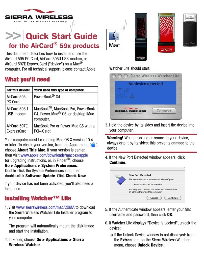
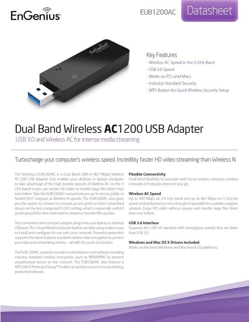
This program used for configuring and testing GM2 and GM3 GSM modems from the RS232 port or
USB port of PC. ( with RS232 – USB converter ).
What you can configure :
1. You can set 8 telephone numbers to send sms when any alarm is occured on UPS.
2. You can set sms language when any alarm is occured on UPS.(Turkish and English)
3. You can set alarm report type. (Only SMS, Only GPRS, SMS & GPRS)
4. You can set Server IP and PORT numbers for GPRS reporting when any alarm is occured on UPS.
5. You can choose any alarm which starts the alarm process by setting alarm maskes.
SETUP
You should click the Tescom’s setup icon double time for installing program.
UPS Side
Modem Side
3
2
5
6
9
7
9 pin D-SUB
connector (male)
RECEIVE
TRANSMIT
GND
RECEIVE
TRANSMIT
GND
9 pin D-SUB
connector (female)

6
Microsoft Framework 4.0 installation is required to run the program.
English language is selected in the window above and the "OK" button is clicked. If the Microsoft
Framework 4.0 is not installed on your PC, the following window appears on your screen.
When the button of "Yes" is clicked in the above window, it connects to Microsoft's link by
using your active explorer program and the following window is opens.
You should click the Download button and after making necessary steps would be installed

7
Microsoft .NET Framework 4 on your PC. You can reach the next step if you repeat the above steps for
installing.
If Microsoft Framework 4.0 installed on your PC, the following window appears in front of you.
Following window appears when clicking the next button.

8
Following window appears when clicking the next button.
Following window appears when clicking the next button.
Following window appears when clicking the next button.

9
If "Install" button is clicked, the program would be installed on your PC.
"Done" button is clicked, the program will be established if the PC.

10
Between the device and your computer, connect your RS232 cable in the box. If you do not have any
COMM-PORT input on your computer, you should provide USB - RS232 converter to connect your
device to your computer.
When you plug the USB – RS232 converter,it may take a different COMM-PORT name on your PC. You
should save this COMM port settings in the Comm Settings of the GSM CONFIGURATOR program.
USAGE
PC Adjust Tab
Run the GSM CONFIGURATOR program. The following window will appear when the program is
executed.
From Com-setup section, click “Search” button, and then following window will appear when you click

11
on the COM PORT list.
After selecting the required COM port, you should click "Open" button.
Thus, you have made the connection between your computer and the modem hardware. You

12
should click red “CONNECT” button in the above window. If there would be no problem the connection
between your PC and your device is provided, the following window appear.
This connection remains active as long as data communication.. If there is no communication between
PC program and GSM modem during 20 seconds, the connection will be lost. You should click
“CONNECT” button to link back.
After this process, if you click “READ FROM MODEM” button, a window will appear as follows and the
modem information (phone numbers, server ip and port 's, etc.) will transfer to the computer.

13
Sms Adjust Tab
If you click the Sms Setting Tab, the following window will appear.
In this tab;
1. In “Telephone Numbers” section, you can set 8 phone numbers and you can choose SMS
language. The places of phone numbers left blank will not be saved.
2. In the “Alarm Select” section, you can choose alarms which trigger the sending sms process.
3. “SAVE” button, you can record the settings to the modem.
4. “TEST SMS” button sends test sms to the mobile numbers that is saved.
GPRS Adjust Tab
If you click “Gprs Adjust” tab, the following window appear.

14
You can set the IP and PORT numbers of the server for GPRS reporting. When entering the IP and PORT
numbers, the gap should be written to 0.
For example : 89-250-192-38 should be written 089-250-192-038.
After sending report , for taking report confirmation from the server, there are two options that are
"Request" and "Not Request". If the response is not necessary, "Not Request" is recommended.
When the “READ FROM MODEM” button is clicked, it will read server IP and PORT which is registered
from modem.When the “TEST GPRS” button is clicked, it will send test gprs report to the server.
General Adjust Tab
General Settings tab, as shown in the following window “ALARM REPORT TYPE” and “USER
PASSWORD” setting can be made.

15
In the ALARM REPORT TYPE section the alarm reporting type is selected to determine how modem
conveys the alarms to the users.
“Only SMS” option sends an SMS to the phone number that was set when the alarm occurred.
“Only GPRS” option sends an alarm report to the servers, which they have IP and PORT values when
the alarm occurs.
"Both SMS and GPRS" also performs with the option of either reporting process when alarms occur.
Command Tab
Sms and gprs settings on the other tabs can be tested in this tab
4.GSM Modem Operation
GSM Modem starts regular operation by connecting modem to UPS with CC05 RS232 cable(green cable) after
configuration process. SIM card should be inserted before powering GSM modem.
GSM modem automatically choses proper communication protocol for respetive UPS model. GSM modem supports
TX100, TX300 and TX301 UPS communication protocols.
GM-3 models have internal battery unit. If GSM modem has external power, batteries will charge(if needed). If
external power is cut off, device will operate on battery energy. This feature allows modem to send SMS to user even
if batteries are empty. After powering GM-3 modem, switch the ON/OFF switch to “ON” position.
Connect power adapter to GM-2 modem during stand alone operation.

16
5.GMB1 external battery unit connection (for GM-2 modem)
There is no internal battery unit in GM-2 modems. Therefore, GM-2 modem is powered from UPS and if UPS output is
closed GM-2 modem will not operate. For operation under such a situation, an external GMB1 battery unit is designed
to work with GM-2 modems. Connection of GMB1 battery unit to GM-2 modem is shown below. When GMB1 battery
unit is connected to GM-2 modem, DC power adapter should be connected to GMB1 battery unit instead of GM-2
modem. Also, ON/OFF switch of the GMB1 battery unit should be switch ON.
DC power adapter
should be conncted
to this connector
Connection
should be made
as shown, with
0.25mm cables
kablolar ile
ON/OFF switch
should be “ON”
alınmalıdır.
If battery voltage is
sufficient this LED will
light up

17
6.Display LEDs
LEDs placed on the front panel of the Modem displays communication status.
Led durumu Açıklama
Comm (Red) Long blinking interval: UPS RS232 connection error
Short blinking interval: UPS RS232 connection established
GSM (Green) Blinking : Searches for GSM signal
Continuous light : GSM signal OK
SIM fault (Red) No light: SIM card inserted
Continuous light: SIM card not inserted
SMS (Green) Blinks on every SMS send operation
GPRS (Green) No light: GPRS not connected
Continuous light: GPRS connected
Ready (Yellow) Continuous light: battery charge is sufficient(for units with battery,
GM-2 with GMB1 battery unit and GM-3)

18
Other manuals for i-com Series
3
This manual suits for next models
3
Table of contents
