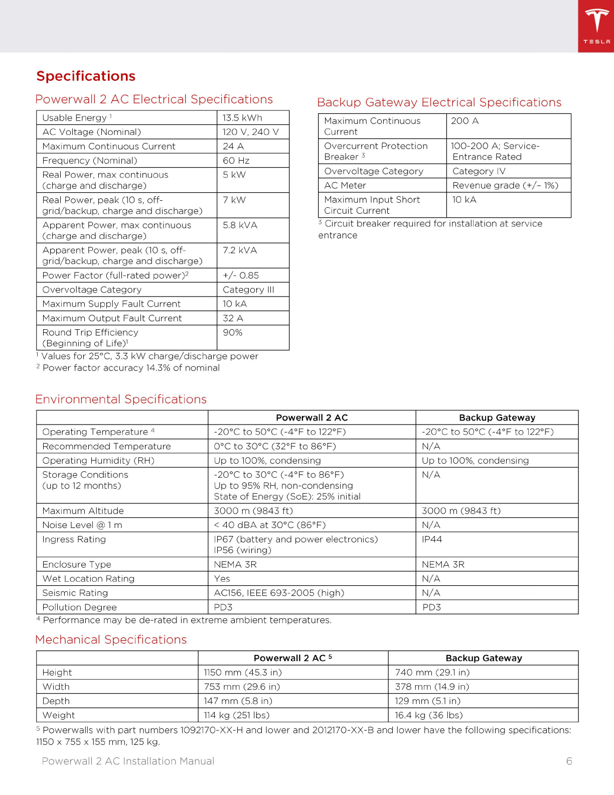
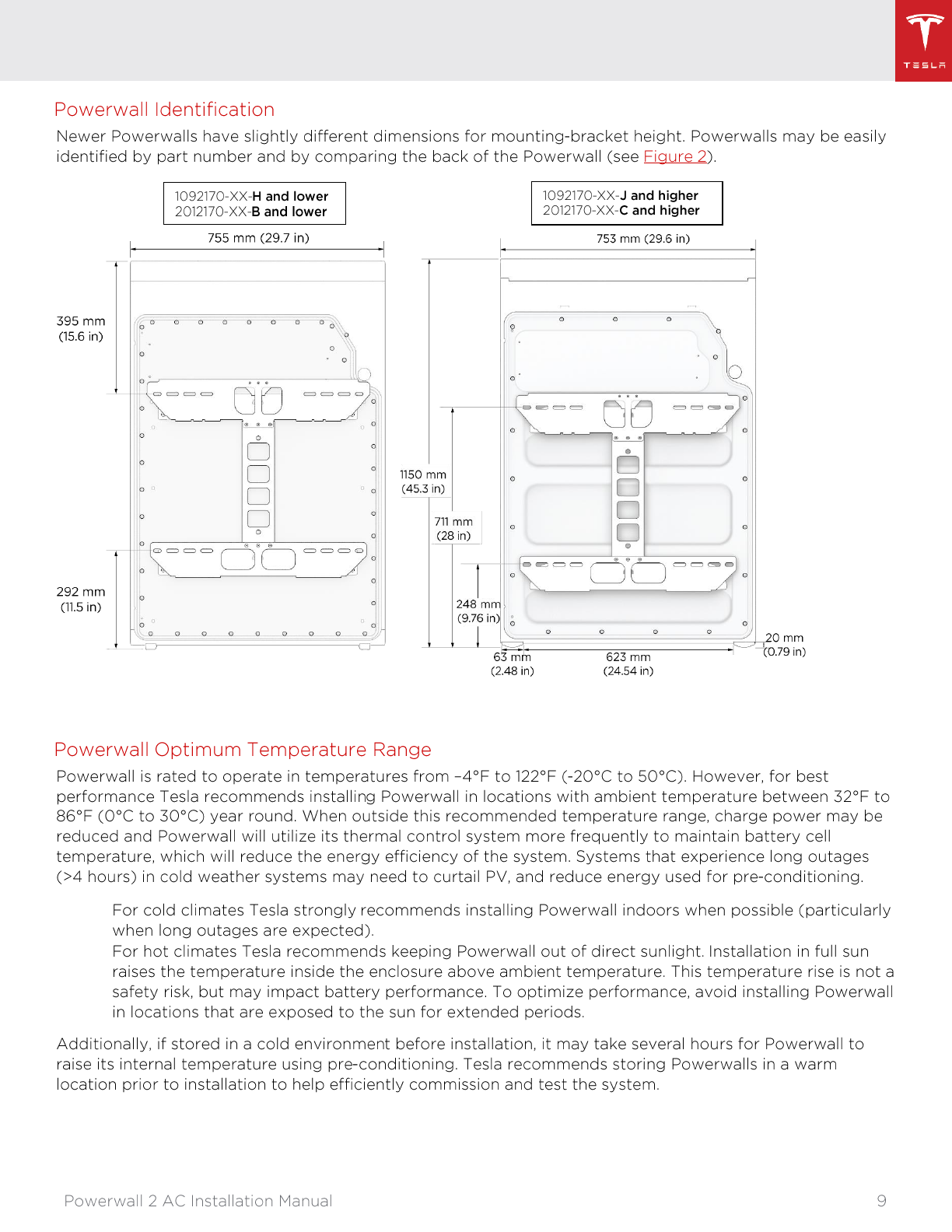
Tesla POWERWALL 2 AC User manual

-
T =5 L M
Powerwall 2 AC Installation Manual
With
Backup
Gateway

PRODUCT SPECIFICATIONS
ERRORS OR OMISSIONS
TESLA
TESLA MOTORS
POWERWALL
FOR PRIVATE HOUSEHOLDS: INFORMATION ON
DISPOSAL FOR USERS OF WEEE
FOR PROFESSIONAL USERS IN THE EUROPEAN
UNION
FOR DISPOSAL IN COUNTRIES OUTSIDE OF THE
EUROPEAN UNION
For
the
latest
Powerwall
installation
documents
in
all
supported
languages,
visit
www.tesla.com/su
pport/powerwa
11
.
To
secure
the
full
10-year
product
warranty,
Powerwall
must
be
registered
by
completing
the
commissioning
process
and
sending
system
information
to
Tesla.
All
specifications
and
descriptions
contained
in
this
document
are
verified
to
be
accurate
at
the
time
of
printing.
However,
because
continuous
improvement
is
a
goal
at
Tesla,
we
reserve
the
right
to
make
product
modifications
at
any
time.
The
images
provided
in
this
document
are
for
demonstration
purposes
only.
Depending
on
product
version
and
market
region
,
details
may
appear
slightly
different.
To
communicate
any
inaccuracies
or
omissions
in
this
manual, send an email to:
enerqy-
.
©2019 TESLA, INC. All
rights
reserved.
All
information
in
this
document
is
subject
to
copyright
and
other
intellectual
property
rights
of
Tesla, Inc.
and
its licensors. This
material
may
not
be
modified,
reproduced
or
copied,
in
whole
or
in
part,
without
the
prior
written
permission
of
Tesla,
Inc.
and
its licensors.
Additional
information
is
available
upon
request. The
following
are
trademarks
or
registered
trademarks
of
Tesla, Inc.
in
the
United
States
and
other
countries:
All
other
trademarks
contained
in
this
document
are
the
property
of
their
respective
owners
and
their
use herein
does
not
imply
sponsorship
or
endorsement
of
their
products
or
services. The
unauthorized
use
of
any
trademark
displayed
in
this
document
or
on
the
product
is
strictly
prohibited.
Powerwall
2
AC
Installation
Manual
ELECTRONIC DEVICE:
DO
NOT
THROW
AWAY
Proper
disposal
of
batteries
is
required.
Refer
to
local
codes
for
disposal
requirements.
This
symbol
on
the
product(s)
and/
or
accompanying
documents
means
that
used
electrical
and
electronic
equipment
(WEEE)
should
not
be
mixed
with
general
household
waste.
For
proper
treatment,
recovery,
and
recycling,
please
take
this
product(s)
to
designated
collection
points
where
it
will
be
accepted
free
of
charge.
Alternatively,
in
some
countries,
you
may
be
able
to
return
your
products
to
your
local
retailer
upon
purchase
of
an
equivalent
new
product.
Disposing
of
this
product
correctly
will
help
save
valuable
resources
and
prevent
any
potential
negative
effects
on
human
health
and
the
environment,
which
could
otherwise
arise
from
inappropriate
waste
handling.
Please
contact
your
local
authority
for
further
details
of
your
nearest
designated
collection
point.
Penalties
may
be
applicable
for
incorrect
disposal
of
this waste, in
accordance
with
your
national
legislation.
If
you
wish
to
discard
electrical
and
electronic
equipment
(EEE), please
contact
your
dealer
or
supplier
for
further
information.
This
symbol
is
only
valid in
the
European
Union
(EU). If
you
wish
to
discard
this
product
please
contact
your
local
authorities
or
dealer
and
ask
for
the
correct
method
of
disposal.
2
II

IMPORTANT SAFETY INSTRUCTIONS
SYMBOLS USED
ATTENTION:
Read
this
entire
document
before
installing
or
using
Powerwall.
Failure
to
do
so
or
to
follow
any
of
the
instructions
or
warnings
in
this
document
can
result
in
electrical
shock, serious injury,
or
death,
or
can
damage
Powerwall,
potentially
rendering
it
inoperable.
This manual
contains
important
instructions
for
the
Tesla
Powerwall
2
AC
and
Backup
Gateway
that
must
be
followed
during
installation
and
maintenance
of
the
system.
A
WARNING
:
indicates
a
hazardous
situation
..
which
,
if
not
avoided
,
could
result in
injury
or
death.
Ii\
CAUTION:
indicates
a
hazardous
situation
lD
which
,
if
not
avoided
,
could
result in
minor
injury
or
damage
to
the
equipment.
NOTE
:
indicates
an
important
step
or
tip
that
leads
to
best
results,
but
is
not
safety
or
damage
related.
REFER
TO
OPERATING
INSTRUCTIONS:
indicates
that
user
should
refer
to
operating
or
installation
instructions
before
proceeding.
Powerwall
2
AC
Installation
Manual
RISK
OF
ELECTRIC
SHOCK:
indicates
components
that
present
risk
of
electrical
shock.
£.
{/'\,
CAUTION,
RISK
OF
ELECTRIC
~
Z.,/
SHOCK,
ENERGY
STORAGE
TIMED
5
minutes
. . .
DISCHARGE
.
Discharge
time
1s
5
minutes
from
de-energization.
~
BIDIRECTIONAL
TERMINAL
:
Indicates
~
location
of
combined
input/output
connector
on
the
equipment.
(T\
PROTECTIVE
CONDUCTOR
TERMINAL
:
'€J
Indicates
location
of
grounding
connection
on
the
equipment.
3
II

GENERAL INFORMATION
II
A
WARNING
:
Read
this
entire
document
before
A
WARNING:
Install
Powerwall
and
Backup
installing
or
using
Powerwall.
Failure
to
do
so
Gateway
in
a
location
that
prevents
damage
or
to
follow
any
of
the
instructions
or
from
flooding
.
warnings
in
this
document
can
result
in A
WARNING:
Operating
or
storing
Powerwall
in
electrical
shock,
serious
injury,
or
death,
or
temperatures
outside
its
specified
range
may
damage
Powerwall,
potentially
rendering
might
cause
damage
to
Powerwall.
it
inoperable
. A
WARNING:
Do
not
expose
Powerwall
to
A
WARNING:
A
battery
can
present
a
risk
of
ambient
temperatures
above
60°C
(140°F)
or
electrical
shock
, fire,
or
explosion
from
vented
below
-30°C
(-22°F)
.
gases
.
Observe
proper
precautions
. &
CAUTION:
Do
not
use
solvents
to
clean
A
WARNING
:
Powerwall
installation
must
be
Powerwall,
or
expose
Powerwall
to
flammable
carried
out
only
by
a
competent
electrician
or
harsh
chemicals
or
vapors.
who
is
certified
by
Tesla
and
who
has
been
&
CAUTION:
Do
not
use
fluids,
parts,
or
trained
in
dealing
with
low
voltage
electricity
.
accessories
other
than
those
specified
in
this
A
WARNING
:
Powerwall
is
heavy
.
Use
of
lift
manual,
including
use
of
non-genuine
Tesla
equipment
is
recommended.
parts
or
accessories,
or
parts
or
accessories
A
WARNING
: Use
Powerwall
only
as
directed
.
not
purchased
directly
from
Tesla
or
a
Tesla-
certified
party.
A
WARNING
:
Do
not
use
Powerwall
if
it
is &
CAUTION:
Do
not
place
Powerwall
in
a
defective,
appears
cracked,
broken,
or
storage
condition
for
more
than
one
(1)
otherwise
damaged,
or
fails
to
operate.
month,
or
permit
the
electrical
feed
on
the
A
WARNING
:
Before
beginning
the
wiring
Powerwall
to
be
severed
for
more
than
one
(1)
portion
of
the
installation,
ensure
that
month,
without
placing
Powerwall
into
a
Powerwall
is
switched
off,
and
lock
out
any
storage
condition
in
accordance
with
Tesla's
associated
circuit
breakers
and
disconnect
storage
specifications
.
switches
(if
applicable
for
the
installation)
. &
CAUTION:
Do
not
paint
any
part
of
Powerwall,
A
WARNING
:
Do
not
attempt
to
open,
including
any
internal
or
external
components
disassemble,
repair,
tamper
with,
or
modify
such
as
the
exterior
shell
or
casing.
Powerwall.
Powerwall
and
its
components
are
&
CAUTION:
Do
not
connect
Powerwall
directly
not
user
serviceable
.
Batteries
in
Powerwall
to
photovoltaic
(PV)
solar
wiring.
are
not
replaceable
.
Contact
Tesla
Support
for
&
CAUTION:
When
installing
Powerwall
in a
guidance
on
repairs
.
garage
or
near
vehicles
,
keep
it
out
of
the
A
WARNING
:
To
protect
Powerwall
and
its
driving
path.
If
possible,
install
Powerwall
on
a
components
from
damage
when
transporting,
side
wall
and/or
above
the
height
of
vehicle
handle
with
care
.
Do
not
impact.
pull,
drag,
or
bumpers
.
step
on
Powerwall.
Do
not
subject
Powerwall
&
CAUTION:
Avoid
installing
Powerwall
and
to
any
strong
force.
To
help
prevent
damage,
Backup
Gateway
in
direct
sunlight
.
leave
Powerwall
in
its
shipping
packaging
&
until
it
is
ready
to
be
installed.
CAUTION:
Ensure
that
no
water
sources
are
above
or
near
Powerwall
or
Backup
Gateway,
A
WARNING
:
Do
not
insert
foreign
objects
into
including
downspouts,
sprinklers,
or
faucets
.
any
part
of
Powerwall.
A
WARNING
:
Do
not
expose
Powerwall
or
its
&
CAUTION:
Ensure
that
snow
does
not
accumulate
around
Powerwall
or
Backup
components
to
direct
flame
.
Gateway.
A
WARNING
:
Do
not
install
Powerwall
near
&
CAUTION:
Avoid
installing
the
Powerwall
and
heating
equipment
.
Backup
Gateway
where
it
will
be
exposed
to
A
WARNING
:
Do
not
immerse
Powerwall
or
its
direct
sunlight
or
ambient
temperatures
components
in
water
or
other
fluids
greater
than
35
deg
C.
Powerwall
2
AC
Installation
Manual 4

Table
of
Contents
Specifications
Registering
P
owe
rwall
Site
Requirements
and
Pre-Installation
Guidance
Installation
Components
and
To
ols
.......
6
....
7
..
7
.....
10
Installation
Instructi
ons
.................................
.. .. .. .. .. .. .. .. .. .. .. .. .. .. .. .. .. .. .. .. .. .. .. .. .. .. .. .. .. .. .. .. .. .. .. .. .. .. .. .. .. .. .. .. .. .. .. .. .. .. .. .. .. .. .. .. .. .. .. .. .. .. .. .. .. .. .. .. .. .. .. .. .. .. .. .. ..
......
12
Step
1.
Plan
the
Installation
Site...........................................
.. .. .. .. .. .. .. .. .. .. .. .. .. .. .. .. .. .. .. .. .. .. .. .. .. .. .. .. .. .. .. .. .. .. .. .. .. .. .. .. .. .. .. .. .. .. .. .. .. .. .. .. .. .. .. .. .. .. .. .. ..
..12
Step
2.
Anchor
the
Po
we
r
wa
ll
Mounting
Bracket
Step
3.
Mount
Po
we
r
wa
ll
on
the
Bracket
Step
4.
Mount
the
Backup
Gateway
Step
5.
Connect
Pow
er
wa
ll
to
the
Backup
Gateway
Step
6:
Make
AC
Pow
er
Connections
................................
.
Step
7.
Install
Energ
y
Metering
for
the
System
Step
8.
Close
the
W
iring
Compartments
and
Turn
the
System
On
Step
9.
Commission
the
System
......
13
......
14
......
16
......
19
..
....
21
.....
23
......
29
....
30
Step
10.
Finish
and
Demonstrate
the
Installation
...
.. .. .. .. .. .. .. .. .. .. .. .. .. .. .. .. .. .. .. .. .. .. .. .. .. .. .. .. .. .. .. .. .. .. .. .. .. .. .. .. .. .. .. .. .. .. .. .. .. .. .. .. .. .. .. .. .. .. .. .. .. .. ..
......
31
Troubleshooting
...............................................................
.. .. ..
.
.. .. .. .. .. .. .. .. .. .. .. .. .. .. .. .. .. .. .. .. .. .. .. .. .. .. .. .. .. .. .. .. .. .. .. .. .. .. .. .. .. .. .. .. .. .. .. .. .. .. .. .. .. .. .. .. .. .. .. .. .. .. ..
.....
32
Technical
Support
...............................
..
..
..
..
..
..
..
..
..
..
..
..
..
..
..
..
..
..
..
..
..
..
..
..
..
..
..
..
..
..
..
..
..
..
..
..
..
..
..
..
..
..
..
..
..
..
..
..
..
..
..
..
..
..
..
..
..
..
..
..
..
..
..
..
..
..
..
..
..
..
..
..
..
..
..
..
..
..
..
.. ..
.....
32
Maintenance
.......................................................................
..
..
..
..
..
..
..
..
..
..
..
..
..
..
..
..
..
..
..
..
..
..
..
..
..
..
..
..
..
..
..
..
..
..
..
..
..
..
..
..
..
..
..
..
..
..
..
..
..
..
..
..
..
..
..
..
..
..
..
..
..
..
..
..
..
.. ..
.....
32
Appendix
A. P
owe
r
wa
ll
Mo
unting
Details
.......
..
..
..
..
..
..
..
..
..
..
..
..
..
..
..
..
..
..
..
..
..
..
..
..
..
..
..
..
..
..
..
..
..
..
..
..
..
..
..
..
..
..
..
..
..
..
..
..
..
..
..
..
..
..
..
..
..
..
..
..
..
..
..
..
..
.. ..
.....
33
P
owe
r
wa
ll
Space
Requirements
Mo
unting
Bracket
Anchoring
Details
........................................................................................................................................................
..
Appendix
B.
W
iring
Reference
..................................
.. .. .. .. .. .. .. .. .. .. .. .. .. .. .. .. .. .. .. .. .. .. .. .. .. .. .. .. .. .. .. .. .. .. .. .. .. .. .. .. .. .. .. .. .. .. .. .. .. .. .. .. .. .. .. .. .. .. .. .. .. .. .. .. ..
Po
we
r
wa
ll
W
iring
................................................................
.. .. .. .. .. .. .. .. .. .. .. .. .. .. .. .. .. .. .. .. .. .. .. .. .. .. .. .. .. .. .. .. .. .. .. .. .. .. .. .. .. .. .. .. .. .. .. .. .. .. .. .. .. .. .. .. .. .. .. .. .. .. .. .. ..
Backup
Gateway
W
iring
P
owe
r
wa
ll
and
Backup
Gate
w
ay
W
iring
Specifications
.....
..
..
..
..
..
..
..
..
..
..
..
..
..
..
..
..
..
..
..
..
..
..
..
..
..
..
..
..
..
..
..
..
..
..
..
..
..
..
..
..
..
..
..
..
..
..
..
..
..
..
..
..
..
..
.
Appendix
C.
System
W
iring
Diagrams
..............
.
...................................................................................................................................
..
W ho
le-Home
Backup
...................................
..
..
..
..
..
..
..
..
..
..
..
..
..
..
..
..
..
..
..
..
..
..
..
..
..
..
..
..
..
..
..
..
..
..
..
..
..
..
..
..
..
..
..
..
..
..
..
..
..
..
..
..
..
..
..
..
..
..
..
..
..
..
..
..
..
..
..
..
..
..
..
..
..
..
..
Partial-Ho
me
Backup
Partial-Ho
me
Backup
w
ith
Meter
Rel
oc
ated
to
Main Panel
W hole-
or
Partial-Home
Backup
w
ith
Two
Meters
.
Appendix
D.
Installation
Troubleshooting
Accessing
the
Po
we
rwall
User
Interface
Updating
Firm
wa
re
.....
33
....
34
....
36
....
36
.....
37
......
38
....
39
....
39
.....
..41
.....
43
..
45
..
...
47
.....
47
..
47
Configuring
Energ
y
Meters
................................
..
..
..
..
..
..
..
..
..
..
..
..
..
..
..
..
..
..
..
..
..
..
..
..
..
..
..
..
..
..
..
..
..
..
..
..
..
..
..
..
..
..
..
..
..
..
..
..
..
..
..
..
..
..
..
..
..
..
..
..
..
..
..
..
..
..
..
..
..
..
.
.....
47
Po
we
r
Cycle
the
System
..............................................
..
..
..
..
..
..
..
..
..
..
..
..
..
..
..
..
..
..
..
..
..
..
..
..
..
..
..
..
..
..
..
..
..
..
..
..
..
..
..
..
..
..
..
..
..
..
..
..
..
..
..
..
..
..
..
..
..
..
..
..
..
..
..
..
..
..
.
.....
48
Appendix
E.
Multi-Po
we
r
wa
ll
Installations
.....
49
Electrical
Equipment
Sizing
and
Overcurrent
Protection
......
.
.............................................................................................................
49
Multi-Po
we
rwall
Installati
ons w
ith
the
Stack
Kit
.....
.. .. .. .. .. .. .. .. .. .. .. .. .. .. .. .. .. .. .. .. .. .. .. .. .. .. .. .. .. .. .. .. .. .. .. .. .. .. .. .. .. .. .. .. .. .. .. .. .. .. .. .. .. .. .. .. .. .. .. .. .. ..
...
54
Appendix
F.
Re
vision Log........
........................
.. .. .. .. ..
.
.. .. .. .. .. .. .. .. .. .. .. .. .. .. .. .. .. .. .. .. .. .. .. .. .. .. .. .. .. .. .. .. .. .. .. .. .. .. .. .. .. .. .. .. .. .. .. .. .. .. .. .. .. .. .. .. .. .. .. .. .. .. ..
.
....
65
Powerwall
2
AC
Installation
Manual
5
II

Specifications
Powerwall
2
AC
Electrical
Specifications
Backup
Gateway
Electrical
Specifications
Usable
Energy
1
13
.5
kWh
AC
Voltage
(Nominal)
120
V,
240
V
Maximum
Co
ntinuous
Current
24
A
Frequency
(Nominal)
60
Hz
Real Po
we
r,
max
continuous
5kW
(charge
and
discharge)
Real Po
we
r,
peak
(10
s,
off-
7kW
grid/backup,
charge
and
discharge)
Apparent
Po
we
r,
max
continuous
5.8
kVA
(charge
and
discharge)
Apparent
Po
we
r,
peak
(10
s,
off-
7.2
kVA
grid/backup,
charge
and
discharge)
Po
wer
Factor
(full-rated
power)
2 +/ -
0.85
Overvoltage
Category
Category
111
Maximum
Supply
Fault
Current
10
kA
Maximum
Output
Fault
Current
32 A
Round
Trip
Efficiency
90%
(Beginning
of
Life)
1
Maximum
Continuous
200
A
Current
Overcurrent
Protection
100-200
A;
Service-
Breaker
3
Entrance
Rated
Overvoltage
Category Category
IV
AC
Meter
Re
ve
nue
grade(+/-
1%)
Maximum
Input
Short
10
kA
Circuit
Current
3
Circuit
breaker
required
for
installation
at
service
entrance
1 Values
for
25°C, 3.3 kW
charge/discharge
po
we
r
2 Po
wer
factor
accuracy
14
.3%
of
nominal
Environmental
Specifications
Powerwall 2 AC
Operating
Temperature
4
-20°C
to
50°C
(-
4°F
to
122
°F)
Recommended
Temperature
0°c
to
30°c
(32°
F
to
86°F)
Operating
Humidit
y (RH)
Up
to
100
%,
condensing
Storage
Conditions
-20°C
to
30°C
(-4°F
to
86°F)
(up
to
12
month
s)
Up
to
95%
RH,
non-condensing
State
of
Energ
y
(So
E
):
25% initial
Maximum
Altitude
3000
m
(9843
ft)
Noise Le
ve
l @ 1m <
40
dBA
at
30°C
(86°F)
Ingres
s
Rating
IP67
(battery
and
power
electronics)
IP56
(wiring)
Enclo
s
ure
T
ype
NEMA
3R
We
t
Location
Rating
Yes
Seismic
Rating
AC156, IEEE
693-2005
(high)
Pollution
Degree
PD3
4
Performance
may
be
de-rated
in
extreme
ambient
temperatures.
Mechanical
Specifications
Powerwall 2 AC s
Height
1150
mm
(
45
.3
in)
W
idth
753
mm
(29.6
in)
Depth
147
mm
(58
in)
W
eight
114
kg
(251
lb
s)
Backup Gateway
-20
°C
to
50°C
(-4°F
to
122°F)
N
/A
Up
to
100%,
condensing
N
/A
3000
m
(9843
ft)
N
/A
IP44
NEMA
3R
N
/A
N
/A
PD3
Backup Gateway
740
mm
(29.1
in)
378
mm
(
14
.9 in)
129
mm
(51
in)
164
kg
(36
lbs)
5 Po
we
r
wa
ll
s w
ith
part
number
s 1092170-XX-H
and
lo
we
r
and
2012170-XX-B
and
lo
wer
ha
ve
the
following
spec
ification
s:
1150
x 755 x 155
mm,
125
kg
Powerwall
2
AC
Installation
Manual 6
II

Registering Powerwall
Tesla
Powerwall
comes
with
a
warranty
whose
term
depends
on
the
connection
of
Powerwall
to
the
Internet.
To
secure
the
full
10-year
warranty
for
Powerwall,
it
must
be
reliably
connected
to
the
Internet
to
allow
remote
firmware
upgrades
from
Tesla. If an
Internet
connection
is
not
established
or
is
interrupted
for
an
extended
period
,
and
Tesla
is
unable
to
contact
the
owner,
the
warranty
may
be
limited
to
4 years.
To
ensure
that
the
owner
can
receive
the
full
10-year
warranty,
be
sure
to
complete
the
commissioning
process
so
that
registration
information
is
sent
to
Tesla.
For
more
information,
refer
to
the
Powerwall
Warranty
for
your
region
at
www.
te
s
la
.c
om
.
Site Requirements and Pre-Installation Guidance
Pow
er
wall
and
Backup
Gate
way
Installation
Requirements
Powerwall
comes
with
a
separate
Backup
Gateway
and
power
meter
to
enable
integration
with
solar
systems
and
the
electrical
grid.
The
Backup
Gateway
communicates
with
the
system
by
means
of
wireless
and
wired
connections.
Wiring
and
conduit
(where
required)
must
be
provided
by
the
installer.
Where
conduit
is
required,
the
installation
must
comply
with
local
codes
and
UL514B
requirements.
AC
isolation
and
interconnection
requirements
between
the
Powerwall
system
and
the
electrical
panel are
subject
to
local codes. Ensure
that
the
installation
meets
local
isolation
and
interconnection
requirements.
All
U.S.
and
Canada
electrical
installations
must
be
done
in
accordance
with
local
codes
and
the
National
Electric
Code
(NEC)
ANSI/NFPA
70
or
the
Canadian
Electrical
Code
CSA
C22.1.
A
WARNING:
All
Powerwalls
in
the
system
must
be
installed
on
the
'
Backup'
side
of
the
Backup
Gateway's
relay.
A
WARNING:
When
Powerwall
is
installed in a
dwelling
unit, fire
detection
and
protection
equipment
should
be
installed in
accordance
with
local
building
and
fire codes.
A
WARNING:
Do
not
connect
the
Backup
Gateway
in
any
way
that
bypasses
or
short-circuits
its relay.
A
WARNING:
Do
not
connect
the
Backup
Gateway
to
the
source
side
only
or
to
the
load
side only. The
Backup
Gateway
must
have
both
source
and
load
connections,
and
must
be
wired
in
compliance
with
local
codes.
! CAUTION: The Manual
Override
switch
inside
of
the
product
must
not
be
used
to
simulate
a
grid
outage
or
take
home
off-grid.
A
main
isolation
switch
should
be
installed
upstream
of
the
Backup
Gateway
for
testing
the
system
and
for
service
purposes.
NOTE: All
installations
must
conform
to
the
laws,
regulations,
codes,
and
standards
applicable
in
the
jurisdiction
of
installation.
The
Backup
Gateway
must
be
wall-mounted
and
can
be
configured
for
cable
entry
at
the
top,
bottom,
or
sides
of
the
enclosure. It requires
adequate
clearance
for
installation
and
cabling
or
conduit.
Wiring
and
conduit
(where
required)
must
be
provided
by
the
installer.
Where
conduit
is
required,
the
installation
must
comply
with
local
codes
and
UL514B
requirements.
Powerwall
2
AC
Installation
Manual 7
II

Figure 1: Powerwall 2 AC and Backup Gateway Dimensions
1150
mm
(45.3
in)
753
mm
(29.6
in)
Powerwall
Physical
Requirements
147
mm
(5.8
in)
740 mm
(29.1
in)
378mm
(14.9 in)
Po
werwa
ll
can
be
mounted
on
a
floor
or
wa
ll,
and
includes
a
mounting
bracket
to
support
either
configuration.
Mounting
Powerwall
must
follow
the
guidance
outlined
in
this
document.
Mounting
requirements
based
on
wa
ll
type
are
provided
in
Appendix
A:
Powerwall
Mounting
Details
129 mm
(5.1
in)
f---
1
Po
werwa
ll
requires
adequate
clearance
for
installation
,
cabling
,
and
airflow.
Do
not
install
anything
above
Po
werwa
ll
that
limits
access
to
the
unit
or
that
might
fall
and
damage
the
unit.
Do
not
mount
Powerwall
horizontally
or
upside
down
.
NOTE: Po
werwa
ll
has a
pump
and
fan
that
produce
a
gentle
hum
during
operation,
comparable
to
a t
yp
ical
refrigerator.
The
noise
le
ve
l
depends
on
the
ambient
temperature
and
the
power
le
ve
l
of
operation.
Consider
these
noise
le
ve
ls
when
choosing
where
to
install Po
werwa
ll.
Powerwall
2
AC
Installation
Manual 8
II

Figure 2: Powerwall 2 Identification by Mounting Bracket Height
•
•
Powerwall
Identification
Ne
wer
Po
werwa
lls ha
ve
slightly
different
dimensions
for
mounting
-
bra
c
ket
height.
Po
werwa
lls
ma
y
be
easily
identified
by
part
number
and
by
comparing
the
back
of
the
Pow
er
wall
(see
Figure
2
).
395
mm
0
(15.6
in
)
0
0
0
0
0
0
0
0
0
292mm
0
(11.5
in)
0
0
1092170-XX-H and lower
2012170-XX-B and lower
755
mm
(29
.7 in)
0 0 0 0 0 0 0 0
0
0
0 i
Oc:=>c=:><:=>
00
c=><=J<=::iO
.!..........!..I
0
□
□
□
□
0
...
0
0
0
0
0
0
0
C)C:::,C::,C::,
DD
c:::>c:::>c::>CJ
0
0
0
0
0 0 0 0 0 0 0 0 0
..
0
1092170-XX-J and higher
2012170-XX-C and higher
753
mm
(29.6 in)
0 0 0
0
-~~i:=,
uu
0 ...
•
1150mm 0
(
45
.3 in)
7
11
mm 0
(28 in) •
...
l 0 ==
oo
=
==
248 m
(9.76
in
) 0 0 0 0 0
63 mm
623
mm
(2.48
in
) (24.54
in)
0
0
0
a
a
0mm
(0.79
in)
Powerwall
Optimum
Temperature
Range
Po
werwa
ll
is
rated
to
operate
in
temperature
s
from
-4
°F
to
122°F (
-20°
C
to
50°C).
H
owever,
for
best
performance
Tesla
recommends
installing
Po
we
r
wa
ll
in
locations
w
ith
ambient
temperature
bet
wee
n
32°F
to
86°F
(0°C
to
30°C
)
ye
ar
round.
W
hen
outside
this
re
co
mmended
temperature
range
,
charge
po
we
r
ma
y
be
reduced
and
Po
werwa
ll
will
utilize
its
thermal
co
ntrol
system
more
frequentl
y
to
maintain
batter
y cell
temperature
, w
hich
will
reduce
the
energy
efficiency
of
the
system.
Systems
that
experience
long
outages
(>
4
hours
) in
co
ld
wea
ther
systems
ma
y
need
to
curtail
P
V,
and
reduce
energy
used
for
pre-conditioning.
For
cold
climate
s Tesla s
trongl
y
recommend
s ins
talling
Pow
er
wall
indoor
s w
hen
possible
(par
ti
cularly
w
hen
long
outages
are
expected).
For
hot
climates
Tesla re
co
mmends
keeping
Po
werwa
ll
out
of
dire
ct
sunlight.
Installation
in full sun
raises
the
temperature
inside
the
enclosure
abo
ve
ambient
temperature
. This
temperature
rise
is
not
a
safety
risk,
but
ma
y
impact
batter
y
performan
ce.
To
optimize
performance
,
avoid
installing
Po
werwa
ll
in loc
ations
that
are
exposed
to
the
sun
for
extended
periods
.
Additionally
,
if
stored
in a
co
ld
environment
before
installation
,
it
ma
y
take
several
hours
for
Po
werw
all
to
raise
its
internal
temperature
using
pre-conditioning.
Tesla
recommends
storing
Po
we
rwalls in a w
arm
location
prior
to
installation
to
help
efficiently
commission
and
test
the
system.
Powerwall
2
AC
Installation
Manual 9
II

•
•
•
•
•
•
•
•
•
•
•
•
•
•
•
•
•
•
•
•
•
•
•
•
Installation Components and Tools
Powerwall
Box
Contents
Powerwall
2
AC
unit
Mounting
bracket
Accessory
Bag
Contents
(1)
3-pin
AC
power
harness
(600
V,
105
deg
C)
(3)
WAGO
lever
nuts
for
AC
power
connections
(1)
4-pin
terminal
block
connector
(black)
for
connection
to
Gateway
(1)
4-pin
terminal
block
connector
(green)
with
120-Ohm
terminating
resistor
(1)
T20
Torx
driver
bit
(1) 1-inch
insulation
bushing
for
conduit
entry
to
Powerwall
(2)
shims
for
leveling
floor-mounted
units
(1)
Safety
Instructions
document
On
the
outside
of
the
box:
printed
Tesla
Battery
Emergency
Response
Guide
(ERG)
Backup
Gateway
Box
Contents
(1)
Backup
Gateway
enclosure
(1) Powerwa/1 2
AC
Owner's
Manual
Accessory
bag
containing
labels
(to
be
applied
only
if
Gateway
is
installed
at
the
service
entrance
with
a
circuit
breaker):
(1)
Rating
label
for
Backup
Gateway
door
(1)
Warning
label
for
Backup
Gateway
dead
front
panel
(1)
Meter
Kit
containing:
(1)
4-conductor
voltage
line harness
(1)
Meter
antenna
extension
cable
(2)
3-pin
wiretaps
(2)
Meter
antenna
extension
knockout
plugs
(1/2-inch
and
3/
4-inch)
(2)
4
mm2
(12
AWG)
wire
jumpers
(2)
Self-drilling
screws
for
mounting
the
meter
(1)
Wirenut
Powerwall
2
AC
Installation
Manual
II
10

•
•
•
•
•
•
•
•
•
•
•
•
•
•
•
•
•
•
Required
Tools
Personal
protective
equipment
(safety
glasses,
gloves
,
protective
footwear)
Drill
and
drill
bit
for
drilling
pilot
holes
in
mounting
surface
Torque
screwdriver
w
ith
1/4-inch
bit
holder
(for
the
provided
T20
Torx
bit)
Large
(5
mm)
flathead
driver
bit
(for
ground
bar)
Small
(2
mm)
flathead
screwdriver
(for
wiring
connector
spring
terminals)
Torque
wre
nch
with
5/16-inch
Allen
bit
(for
Backup
Gateway
power
connections)
Wire
strippers/cutters
for
0.2
mm2
to
120
mm2
(24
AWG
to
250
kcmil)
wires
Installation
tools
(level,
stud
sensor
,
tape
measure,
pencil,
painter
's
tape
,
flashlight)
Lift
equipment
capable
of
lifting
and
supporting
125
kg
(276
lbs)
Ratcheting
strap
to
secure
Po
we
r
wa
ll
to
lift
equipment
Digital
camera
or
smartphone
for
documenting
the
installation
A
WARNING:
Po
we
r
wa
ll
is
heavy.
Wear
appropriate
personal
protective
equipment
(such
as
gloves
and
protective
footwear)
w
hen
handling
the
unit.
Only
a
sufficient
number
of
trained
mo
vers
should
lift
Po
werwa
ll.
Use
of
lift
equipment
is
recommended.
Required
Supplies
Po
werwa
ll
mounting
bracket
hard
wa
re
(see
Appendix
A)
Conduit
fitting
or
cable
gland
(depending
on
local
electrical
requirements)
Conduit
or
race
way
(depending
on
local
electrical
requirements)
Minimum
300
V
rated
4-conductor
(with
one
tw
isted
pair)
shielded
copper
(Cu)
cable
(for
communication
connection
between
Po
we
r
wa
ll
and
the
Backup
Gateway)
Minimum
600
V,
90
deg
Crated
copper
(Cu)
cable
(for
po
we
r
connections
to
Po
we
rwall
and
the
Backup
Gateway)
Conduit
adapter
(if
necessar
y
for
cable
entry
into
Po
werwa
ll
w
iring
compartment)
Siemens
HS-style
conduit
hub
(for
entry
into
the
top
of
the
Backup
Gateway
enclosure)
Powerwall
2
AC
Installation
Manual
II
11

•
•
•
•
•
•
Installation Instructions
Step
1.
Plan
the
Installation
Site
0
I
I
I
0
[]
I
[]
I
0
I
D
Choose a Location
Choose
a
wall
capable
of
supporting
the
full
weight
of
Powerwall
,
with
one
of
the
following
characteristics:
Wood
studs
at
regular
intervals
Plywood
sheeting
of
sufficient
thickness
Solid
concrete
or
masonry
Metal
studs
of
sufficient
gauge
If
floor-mounting
Powerwall
,
choose
a level
surface
adjacent
to
a
wall
space
that
meets
the
above
requirements.
Make
sure
the
area
is
isolated
from
hazards
that
could
damage
Po
werwa
ll,
such
as
vehicle
traffic
or
flooding.
Consider
the
spacing
requirements
for
Powerwall
(see
Appendix
A:
Pow
er
wall
Mounting
Detail
s).
Choose Side or Rear Cable Entry for Powerwall
Determine
w
hether
cables
wi
ll
be
routed
into
Po
werwa
ll
from
the
side
or
the
back
of
the
unit.
For
side
cable
entry,
a
conduit
fitting
or
cable
gland
must
be
used
to
seal
the
entry
into
the
w
iring
compartment.
For
back
cable
entry,
a
rubber
grommet
or
cable
gland
is
used
to
seal
the
entry
into
the
wiring
compartment.
NOTE:
If
Power
wa
ll
is
mounted
on
a
wa
ll
w
ith
studs
spaced
24
in (610
mm)
apart,
cable
entry
from
the
back
of
Powerwall
may
be
blocked.
Choose Top, Bottom, or Side Cable Entry for Backup
Gateway
Determine
w
hether
cables
wi
ll
be
routed
into
the
Backup
Gateway
from
the
top,
bottom,
or
side
of
the
enclosure.
When
cable
entry
is
from
the
bottom
half
of
the
enclosure,
the
back
panel
of
the
unit
may
be
rotated
180
degrees
to
simplify
cable
runs.
NOTE:
For
cable
entry
at
the
top
of
the
Backup
Gateway
enclosure,
an
HS-style
hub
should
be
used
in
order
to
maintain
enclosure
ingress
protection.
Plan the Electrical Service Connection
to
Backup Gateway
The
Backup
Gateway
is
service
entrance
rated,
and
can
be
located
between
the
service
entrance
and
the
main
electrical
panel.
When
installed
at
the
service
entrance,
appropriate
overcurrent
protection
must
be
installed
in
the
Backup
Gateway.
The
Backup
Gateway
can
accommodate
t
wo
different
circuit
breaker
sizes:
100/125
A
or
150/200
A
Conduit or raceway:
Calculate
the
amount
and
size
of
conduit
or
raceway
needed
for
the
installation,
based
on
fill
limits
and
local
code
requirements.
With
conduit,
an
adapter
may
be
required
between
the
entry
into
the
Po
werwa
ll
wi
ring
compartment
and
the
conduit.
Plan Distance Between Components
Follo
w
the
table
below
for
maximum
distances
between
system
components.
Wire
gauge
must
meet
local
codes
and
in
some
circumstances
wire
gauge
requirements
change
based
on
distance.
Refer
to
Appendix
B
for
wire
gauge
requirements.
Maximum
Cable
Length
Backup
Gateway
to
Po
werwa
ll(s)
* 150
ft
(45
m)
Neurio
Energy
Meter
to
Backup
Gateway
(RS485
w
ired
connection)
164
ft
(50
m)
Backup
Gateway
to
Internet
router
(wired
Ethernet
connection)
328
ft
(100
m)
*Total length
of
communications cable, including daisy-chained connections, through last
Po
werwa
ll
in
chain
CAUTION
:
Failure
to
follow
minimum
cable
size
and
length
requirements
may
result
in
intermittent
or
unreliable
operation
of
the
Po
werwa
ll
system.
In
systems
that
do
not
meet
these
minimum
requirements
,
performance
issues
may
arise
even
after
successful
commissioning.
Powerwall
2
AC
Installation
Manual
12
II

Figure 3: Mounting Bracket Dimensions
Figure 4: Location of Back Cable Entry Port in Relation to Bracket
Step
2.
Anchor
the
Powerwall
Mounting
Bracket
NOTE:
For
detailed
instructions
on
mounting
Po
werw
all,
including
minimum
spacing
requirements,
refer
to
Appendix
A
1.
Us
ing
a
drill
and
le
ve
l,
mount
the
bracket
to
the
se
lected
wall. See Pow
er
wall
Mounting
Detail
s
for
additional
details
on
the
t
ype
and
number
of
fas
tener
s
to
u
se.
582
mm
(23
in)
659
mm
(26 i
n)
61
omm
(2
4
in)
508 mm
(20
i
n)
406 mm 16
in)
305 mm
(12
in)
0
D
D
D
D
0
640 mm (25.2
in)
463
mm
(18.2
in}
2.
For
back
cable
entry
ins
tallation
s,
drill
a
hole
in
the
wa
ll
corresponding
to
the
back
cable
entry
port.
¢35mm
(1.375
in)
14 mm
(0.55
in)
,------ -
--------------------------------
1 ·
...............................
.
-----------------
rt~·
"
::
:::
;::
::
1092170-XX-H and lower
2012170-XX-B and lower
Powerwall
2
AC
Installation
Manual
035mm
14
mm
(0.55
in)
_____.
..,__
(1.375
in)
1092170-XX-J and higher
2012170-XX-C and higher
13
II

Step
3.
Mount
Powerwall
on
the
Bracket
1.
Switch
off
Po
we
r
wa
ll
.
A
WARNING:
Switching
off
will
ensure
Powerwall
does
not
grid
form.
However,
AC
voltage
may
still
be
present
from
the
grid
Ensure
all
equipment
is
safely
de-energized
before
work
ing.
2.
Remo
ve
the
left
side
cover
from
Po
werwa
ll.
3.
For
side
cable
entry
installations
,
remove
the
side
cable
entry
door
from
the
left
side
cover.
4.
For
back
cable
entry
installations,
remove
the
plug
from
the
back
cable
entry
port
and
place
it in
the
s
ide
cable
entry
port.
NOTE:
The
plug
must
always
be
placed
in
either
the
back
or
side
cable
entry
port
Powerwall
2
AC
Installation
Manual
I
14

:
Figure 5: Mounting Powerwall on the Bracket
5.
Using
lift
equipment,
position
Powerwall
close
to
the
wa
ll
and
adjust
the
height
of
Powerwall
until
it
s
mounting
cleats
are
just
above
the
flange
s
on
the
bracket.
6.
Lo
wer
Powerwall
until
the
top
cleat
engages
the
top
flange
on
the
bracket
and
the
bottom
cleat
aligns
with
the
bottom
flange.
7.
W
ith
both
cleats
engaged,
lo
wer
Powerwall
onto
the
bracket.
An
audible
click
will
be
heard
when
the
cleats
are
seated
in
the
bracket
and
the
locking
mechanism
at
the
center
of
the
top
flange
clicks
into
place.
NOTE
To
remove
Powerwall
from
the
mounting
bracket,
place
a
thin
piece
of
sheet
metal
between
the
Powerwall
unit
and
the
bracket
to
compress
the
lo
cking
mechanism,
and
lift
the
Powerwall
straight
up.
8.
If
floor-mounting
Powerwall,
use
the
provided
sh
im
s
to
ensure
that
Powerwall
is le
ve
l.
The
unit
shou
ld
be
le
ve
l w
ithin
+/ - 2
degrees
s
ide-to-
s
ide
and
w
ithin+
/ - 5
degrees
front-to-back.
9.
If
wa
ll-mounting
Powerwall,
remove
the
feet
from
the
unit
(app
li
cab
le
only
to
updated
versions
of
Powerwall,
see
Figure
2).
Powerwall
2
AC
Installation
Manual
15
II

•
•
Step
4.
Mount
the
Backup
Gate
way
1.
Open
the
Backup
Gate
way
enclosure
and
remo
ve
the
enclosure
door.
2.
Remo
ve
the
screw
at
the
bottom
of
the
dead
front
panel
and
remo
ve
it
from
the
enclosure.
3. If
configuring
the
Bac
kup
Gate
way
for
cable
entr
y
from
the
bottom
or
side
s,
do
the
follo
wing:
Remo
ve
the
four
fas
tener
s
holding
the
back
panel a
ss
embl
y in
place
and
remo
ve
it
from
the
enclo
sure.
Rotate
the
back panel assembly 180
degrees
and
reinstall
it
in
the
enclosure.
Powerwall
2
AC
Installation
Manual
--------
~~
.~
""""""'-=
--
-..
-
§
□
e
~
... ,© ©
o·o·
roo
·oo
c:=,~
~
..
16
II

•
•
•
Remove
and
rotate
the
dead
front
panel
insert
(and
its
insulation)
180
degrees,
and
reattach
it
to
compensate
for
the
inverted
back
panel.
---
-
--
- -
,()
[DJ
- - - - - - - - - - -
""O
4.
If
the
Backup
Gateway
is
to
be
located
between
the
electrical
service
entrance
and
the
main
electrical
panel, install a
circuit
breaker
as
follo
ws.
A
WARNING:
If a
circuit
breaker
is
not
added
to
the
Backup
Gateway,
ensure
that
appropriate
overcurrent
protection
is
provided
for
the
installation.
!
CAUTION
: To
reduce
the
risk
of
fire
,
connect
only
to
a
circuit
provided
w
ith
200
A
maximum
branch-
circuit
overcurrent
protection,
in
accordance
w
ith
the
National
Electrical
Code,
ANSI/NFPA
70.
The
following
circuit
breaker
models
(purchased
separately)
are
supported:
Circuit Breaker Model UL
Type
Siemens
MBK
100A
EQ8681
Siemens
MBK
125A
EQ8682
Siemens
MBK
150A
EQ8693
Siemens
MBK
200A
EQ8695
Determine
the
level
of
overcurrent
protection
required,
based
on
local
code
requirements.
Remo
ve
the
service
inlet
terminal
lugs
from
the
Backup
Gateway.
(It
may
be
Rating
100
A
125
A
150 A
200
A
necessary
to
remo
ve
the
meter
current
l@fl
l@ll
~il~~~~;;~u~s
~~cp~!~!~e MlO
nuts
@>
•
~-
_
-j::
:"fil:
Powerwall
2
AC
Installation
Manual
Current
at
50
°c
87
A
110
A
130A
170 A
---
Current
at
30
°c
100
A
125
A
150 A
200
A
II
17

•
•
Install
the
corresponding
size
circuit
breaker
at
the
service
inlet
terminals
in
the
Backup
Gateway,
and
replace
the
Ml0
nuts
to
secure
the
breaker.
Tighten
the
nuts
to
5.6
Nm
(50
lb-in).
Remove
the
appropriate
punch-outs
in
the
dead
front
panel
insert
for
the
circuit
breaker
as
shown
below.
For
smaller
(100
A
or
125
A)
circuit
breakers,
remo
ve
punchouts
Band
C;
for
larger
(150 A
or
200
A)
circuit
breakers,
remove
punchouts
A
and
B.
5.
Using
a
drill
and
le
ve
l,
mount
the
Backup
Gateway
enclosure.
NOTE:
Mount
the
Backup
Gateway
ve
rticall
y,
in
the
orientation
shown
below.
Do
not
mount
the
Backup
Gateway
horizontall
y
or
upside
down.
6.
Locate
the
Backup
Gateway
serial
number
on
the
label
on
the
ins
ide
of
the
enclosure
door.
Record
the
serial
number
for
reference.
41
mm
(1.6
in)
528mm
(20.8
in)
_l_
'
267mm
(10.5
in)
(fob
~ ~
133 mm
(5.2
in)
~
~
@
Powerwall
2
AC
Installation
Manual
695mm
(27.3
in)
II
18

Figure 6: Communication Connector Wiring
Step
5.
Connect
Powerwall
to
the
Backup
Gateway
NOTE: Refer
to
Appendix
B for wiring specifications.
Depending
on
local
requirements,
Powerwall
wiring
can
be
installed
through
conduit
or
through
a
cable
gland.
Refer
to
local
codes
to
determine
wiring
requirements.
1.
(Conduit
installations
only)
Run
conduit
as
needed
and
attach
the
conduit
fitting
to
the
inlet
of
the
wiring
compartment.
The
wiring
compartment
inlet
accepts
a
standard
1-inch
conduit
fitting.
2.
(Conduit
installations
only)
If
the
conduit
connector
does
not
have
an
integrated
bushing,
affix
the
provided
insulation
bushing
to
the
conduit
opening
on
the
inside
of
the
wiring
compartment.
NOTE:
Ensure
that
all
conduit
joints
and
outlets
have
smooth
edges
so
that
wiring
is
not
damaged
as
it
is
run
through
the
conduit.
3.
Run
the
4-conductor
communication
cable,
the
AC
power
conductors,
and
equipment
grounding
conductor
from
the
Backup
Gateway
through
the
conduit
or
cable
gland
and
pull
them
into
the
Powerwall
wiring
compartment.
4.
On
each
end
of
the
4-conductor
communication
cable,
strip
and
insert
the
wires
into
the
provided
4-pin
connectors
(
Figure
6).
On
the
Powerwall
side
, use
the
black
connector
provided
in
the
accessory
bag.
On
the
Backup
Gateway
side
, use
the
connector
that
came
plugged
into
the
corresponding
connector
socket
in
the
Backup
Gateway.
5.
On
the
Backup
Gateway
side
of
the
4-conductor
communication
cable,
cut
the
cable
shield. The shield
should
be
terminated
at
the Powerwa/1 chassis Earth terminal only.
6.
On
the
Backup
Gateway
side,
strip
the
end
of
the
equipment
grounding
conductor
and
insert
it
in
the
ground
bar
in
the
Backup
Gateway
enclosure
(
Figure
7
).
The
ground
bar
is
identified
with
the
following
symbol:@.
Tighten
the
screw
in
the
Backup
Gateway
ground
bar
to
5.5
Nm
(50
lb-in).
Powerwall
2
AC
Installation
Manual 19
II

Figure 7: Backup Gateway Ground and Communication Connections
Figure 8: Powerwall Earth/Ground and Communication Connections with Terminating Resistor
-
Ground
---
• •
SHIELD
•• • • • • •
-
12v+
-----
l'I
GND
-
CN+
- ~ ~ ~ ,
._.
-
CN-
7.
On
the
Backup
Gateway
side,
plug
the
4-pin
connector
into
the
4-pin
socket
labeled "Po
werwa
ll
".
Tighten
screws
on
the
connector
(see
Backup
Gate
w
ay
Wiring
in
Appendix
B
).
8.
On
the
Powerwall
side,
plug
the
4-pin
connector
into
the
bottom
4-pin
socket
(labeled
"
IN
")
in
the
Po
werwa
ll
w
iring
compartment.
9.
Plug
the
provided
4-pin
connector
with
the
terminating
120-Ohm
resistor
into
the
top
4-pin
socket
(labeled
"OUT")
in
the
Po
we
r
wa
ll
w
iring
compartment.
(In
multi-Powerwall
installations, use
this
connector
only
in
the
la
st Po
werwa
ll
in
the
chain.)
10
.
On
the
Po
we
r
wa
ll
side,
strip
the
end
of
the
equipment
grounding
conductor
and
w
rap
the
communication
cable
drain
wire
around
the
grounding
conductor
lead.
11.
Insert
the
grounding
conductor
and
drain
wire in
the
Po
werwa
ll
chassis
Earth
terminal
(
Figure
8). The
Earth
terminal
is
identified
w
ith
the
following
symbol:
@.
Tighten
the
screw
in
the
Earth
terminal
to
4.5 Nm. =
-----
..
~
..
-
12v+
____
_.
GND
-CN+
CN
-
10®01
~
00
[L~
0
&
·-----
--
·SHIELD ,
______________________
,.
=Ground
------------------
Powerwall
2
AC
Installation
Manual
20
II
Other manuals for POWERWALL 2 AC
6
Table of contents
Other Tesla Camera Accessories manuals