Tesla SOLARGLASS User manual

1
1551592-00-B
SOLARGLASS
INSTALLATION MANUAL
S20-0049

2
1551592-00-B
NOTICES
The information in this manual is believed to be reliable, but does not constitute an express or
implied warranty. Tesla reserves the right to make changes to its PV Modules and other products,
DISCLAIMER OF LIABILITY
to follow the instructions and guidelines found in this manual, or from inappropriate use or
maintenance of PV Modules. This includes, without limitation, any damages, losses, and expenses
caused by non-observance of the instructions of this manual, as well as damages, losses, and
expenses caused by, or in connection with, products of other manufacturers.
CONTACT INFORMATION
SOLAR SYSTEMS TECHNICAL PUBLICATIONS
TESLA, INC
3500 Deer Creek Road
Palo Alto, CA 94304 U.S.A.

3
1551592-00-B
All instructions must be read and understood before attempting to install, wire, operate, or maintain
a PV system. Failure to read and comply with any of the limitations noted herein can result in
property damage, serious bodily injury, or death.
The installer assumes the risk of all injury that might occur during installation, including, without
limitation, the risk of electric shock.
Tesla Solarglass is engineered to safely withstand applicable live loads required by building code for
steep slope applications. However, to ensure safety and maintain maximum roof life, walking on a
Solarglass roof should be avoided except by trained Tesla Solarglass installation professionals and
clay, concrete, and composite tile products.
IMPORTANT SAFETY INSTRUCTIONS
NOTE TO TRAINED PROFESSIONALS
DANGER: Tesla Solarglass is slippery and is a fall hazard. Only access a Solarglass roof with appropriate
safety equipment and while wearing personal fall protection. An approved and safe walking platform
should be used when accessing the roof to prevent falls, and damage to the roof. In addition,
skylights, roof openings and light transfer panels must be covered with approved covering to
prevent falls.
they have been disconnected from the inverter, partly or entirely destroyed, or the system wiring
hazards from the PV system, and stay away from all elements of the PV system during and after a
DANGER:
SAVE THESE IMPORTANT SAFETY INSTRUCTIONS
•
and knowledge.
• Abide by local, regional, and national statutory regulations when installing the system, and
obtain a building permit if necessary.
• Use equipment, connectors, and wiring suitable for solar electric systems.
• Work under dry conditions and use dry tools.
•
• Use insulated tools that are approved for working on electrical installations.
•
as fall hazards or electrical hazards.
•

4
1551592-00-B
SOLARGLASS MODULE INFORMATION
Dimensions
Appx. 5 mm module thickness with 35.3 mm maximum height from deck
Principal Materials Glass, Polymers, Fiberglass and Silicon
Installed System Weight
Installed weights include all components of system above roof sheathing
These electrical characteristics are within ± 5% of the indicated values of Isc, Voc, and Pmax under standard test conditions
2
MODEL #SR60T1 14-CELL MODULE
CERTIFICATIONS
UL Listed ETL Listed
Maximum system voltage: 600 V
ELECTRICAL CHARACTERISTICS
Irradiance
2
Temp.
Voc
Vmp
Isc
Imp
Pmax
25 5.65 5.32

5
1551592-00-B
TRADITIONAL PV TESLA SOLARGLASS
DC modules DC modules
Tempered glass Tempered glass
Silicon cells Silicon cells
Backsheet & encapsulant Backsheet & encapsulant
Module J-boxes, PV wire and Listed connectors Module J-boxes, pv wire and Listed connectors
Series strings below 600 V Series strings below 600 V
DC - AC inverters DC - AC inverters
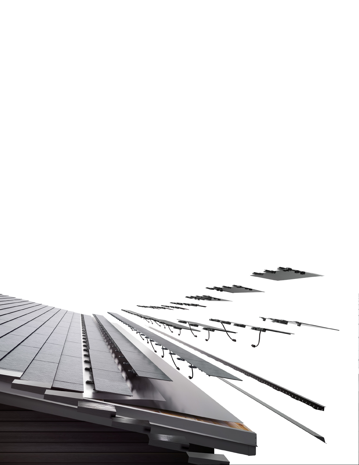
SOLARGLASS SYSTEM OVERVIEW
A Solarglass roof functions in fundamentally the same way as traditional roof-mounted PV systems.
Sunlight is converted to DC electricity at each individual module. Each module is individually connected
energy to a typical string inverter.
PV Modules
TILE TYPES

6
1551592-00-B
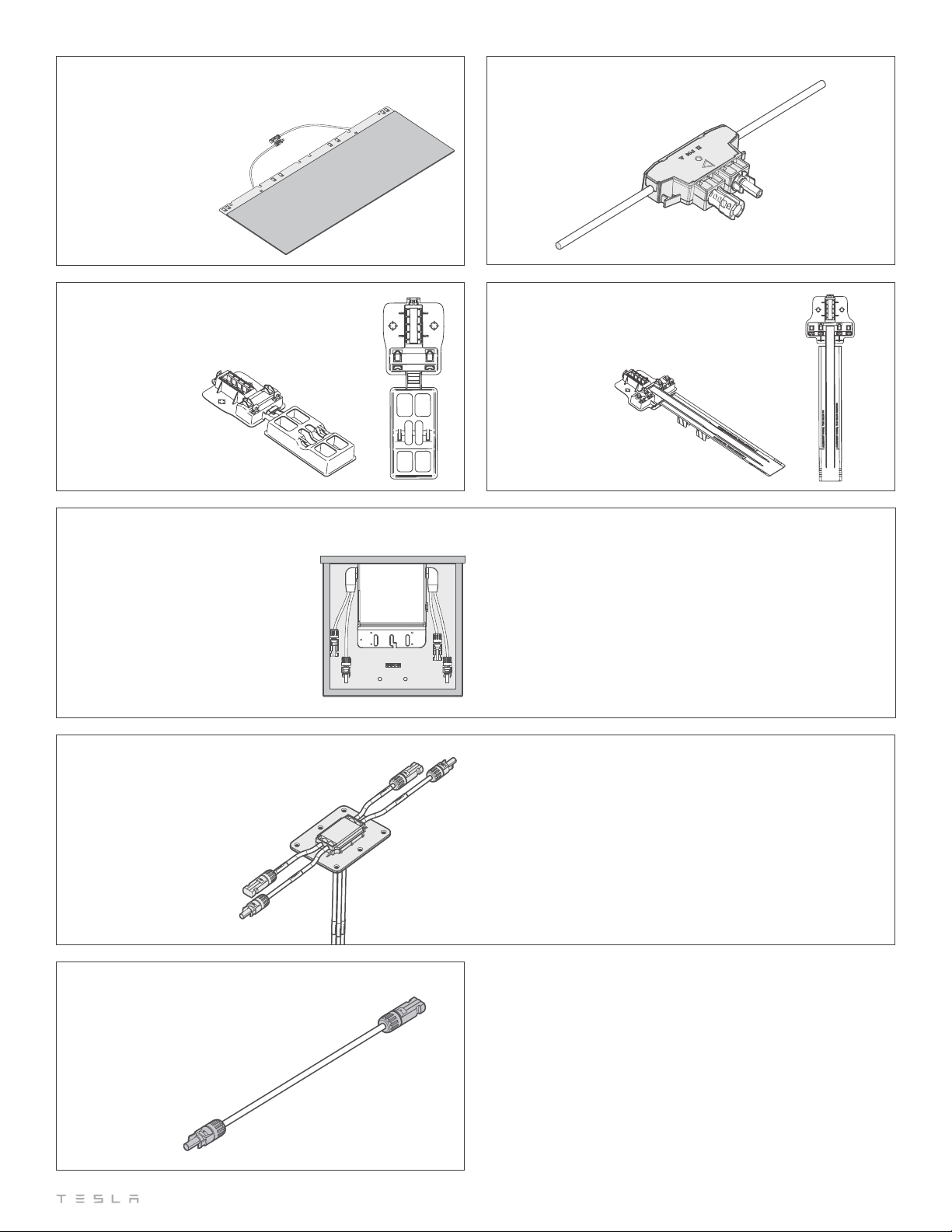
ELECTRICAL SYSTEM COMPONENTS
Diode Trunk Harness
2. PV Module
3. Module lead with connector
4. Foot with Support
5. Footlap
6. Branch Jumper
Pass Through Box
1
2
3
4
5
7
1
2
3
45
6
7
1551592-00-B
BRANCH JUMPER
Model #SR-BJ2X, #SR-BJ3X
#SR-BJ4X, and #SR-BJMini
PASS THROUGH BOX
Model #SRPTB-4
Provides a method of transferring up to 2 PV source circuits through
additional PV arrays.
RAPID SHUTDOWN DEVICE
NEMA 3R Enclosure
Disrupts the PV circuit, disconnecting PV from inverter and removing
residual voltage and current on conductors. This is designed to
leaving the roof. Conductors on roof remain energized.
NEC 2014:
NEC 2017:
DIODE TRUNK HARNESS
Model #SRDTH
Center foot for PV module
FOOT WITH SUPPORT
Model #SR-FOOTSUP
Edge foot for PV module
FOOTLAP
Model #SR-FOOTLAP
PV MODULE
8
1551592-00-B
SHEATHING REQUIREMENTS
the capacity of the existing structure to carry this additional load. As this procedure is beyond the
ROOF PITCH RANGE
UNDERLAYMENT
Firestone Clad-Gard SA FR
Meets or exceeds requirements of ASTM D226 Type I & II
ROOFING SPECIFICATIONS
9
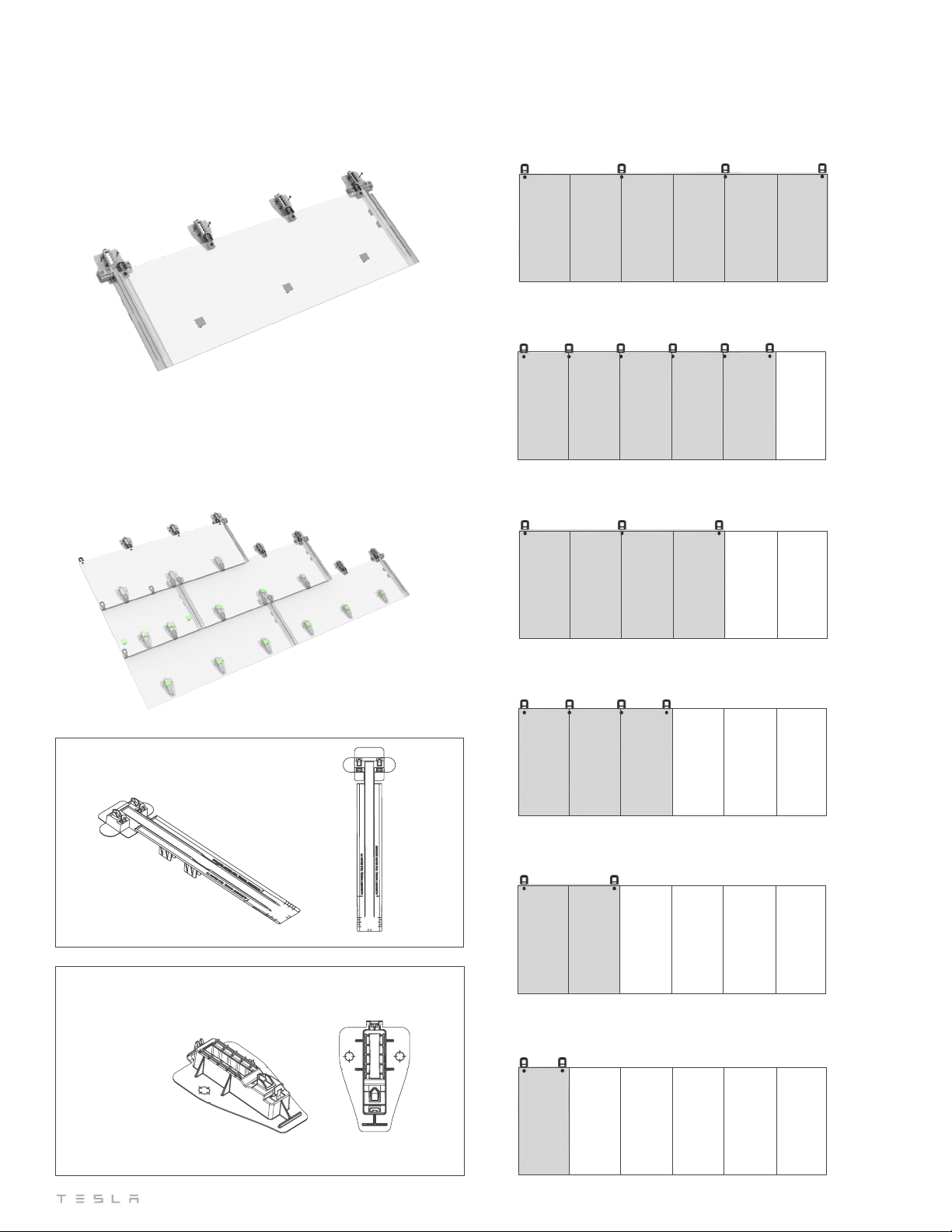
1551592-00-B
1/2 PARTIAL TILE
1/3 PARTIAL TILE
1/6 PARTIAL TILE
2/3 PARTIAL TILE
5/6 PARTIAL TILE
FULL TILE
ROOFING TILES, FULL AND PARTIALS
REDUCED FOOTLAP
Model # SR-RFOOTLAP
to accomodate all areas of the mounting plane and are cross
compatible with the PV Module hardware. The center foot is
edge foot.
ROOFING TILES AND PARTIALS
ROOFING FOOT
Model #SR-FOOT
10
1551592-00-B
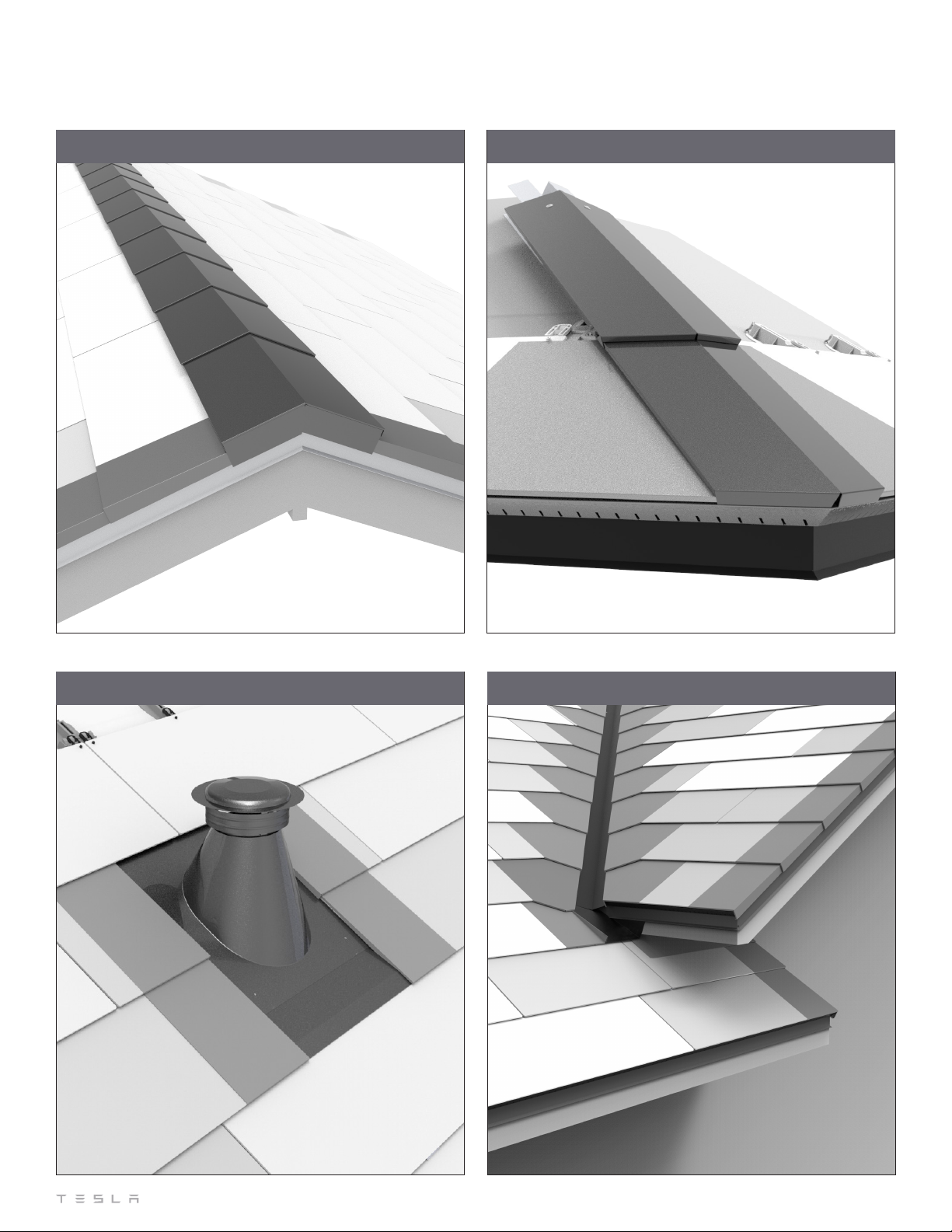
STEPPED HIP DETAILSTEPPED RIDGE DETAIL
OBSTRUCTION DETAIL VALLEY DETAIL
FLASHING COMPONENTS
Table of contents
Other Tesla Solar Panel manuals


