Introduction
www.ti.com
2SBVU026A–January 2015–Revised February 2019
Submit Documentation Feedback
Copyright © 2015–2019, Texas Instruments Incorporated
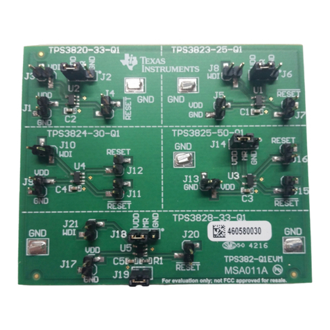
TPS3702CX33EVM-683 High accuracy window voltage detector evaluation
module for OV/UV monitoring
1 Introduction
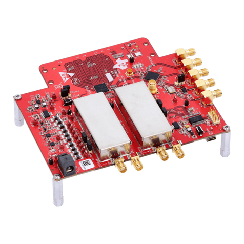
The Texas Instruments' TPS3702CX33EVM-683 EVM helps design engineers to evaluate the operation
and performance of the TPS3702 family of overvoltage and undervoltage monitors for possible use in their
own circuit applications. This particular EVM configuration contains the TPS3702CX33 window voltage
detector for overvoltage and undervoltage monitoring with open-drain output, in a 6-pin, DDC (SOT)
package. The TPS3702 is a high-accuracy window voltage detector with fixed-voltage threshold options
and a wide range of operational supply voltages. The nominal voltage rail that the device monitors is
indicated by the last two digits of the part number. In this case, 33 indicates the fixed threshold version
intended to monitor a nominal rail of 3.3 V. This document describes the configuration and setup of the
TPS3702CX33EVM-683.
2 Hardware
This section describes the connectors on the EVM, as well as how to properly connect, set up, and use
the TPS3702CX33EVM-683.
2.1 Input and Output Connectors
2.1.1 J1 and J2: VCC
The power-supply connectors. Two terminals are provided for multiple connections.
NOTE: The TPS3702 data sheet uses VDD to denote the power supply. In this case, VCC and VDD
are functionally equivalent.
2.1.2 J3 and J4: GND
Return connectors for the input power supply. Two terminals are provided for multiple connections.
2.1.3 J5 and J6: OV
These terminals connect to the overvoltage output. Connect this output to a multimeter, oscilloscope, or
external circuit to verify that OV goes low when SENSE exceeds the overvoltage threshold. Two terminals
are provided for multiple connections.
2.1.4 J7 and J8: UV
These terminals connect to the undervoltage output. Connect this output to a multimeter, oscilloscope, or
external circuit to verify that UV goes low when SENSE drops below the undervoltage threshold. Two
terminals are provided for multiple connections.
2.1.5 JP1: SET
This jumper is used to the connect the SET pin to VCC or GND. To connect the SET pin to a voltage other
than VCC or GND, connect an external source to the center pin. The SET pin has a maximum operational
rating of 6.5 V, but VCC can tolerate 18 V; therefore, a resistor divider is used to help safeguard against
electrically overstressing this pin when shorting SET to VCC using the jumper. See Section 2.2.4 for more
information on the resistor divider.
NOTE: Force the SET pin high or low. Floating the SET pin may require the device to be reset.
