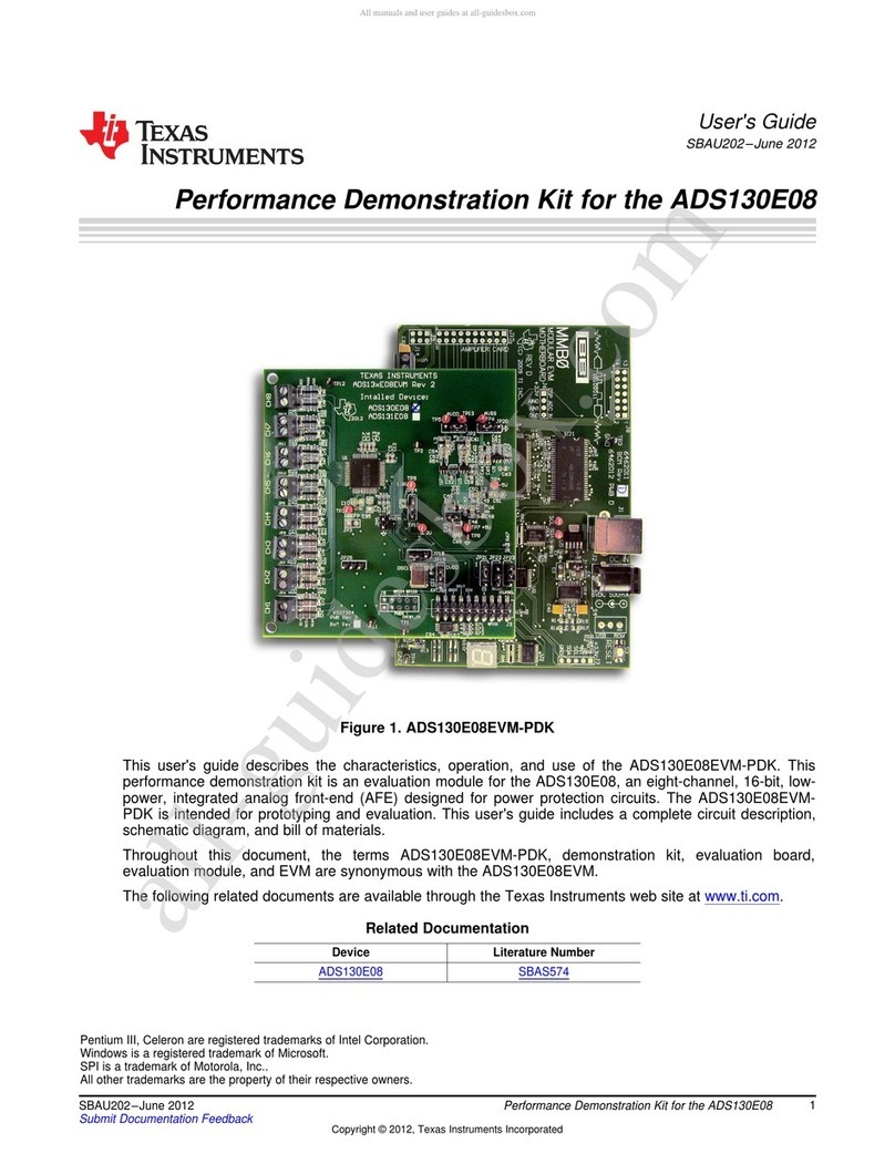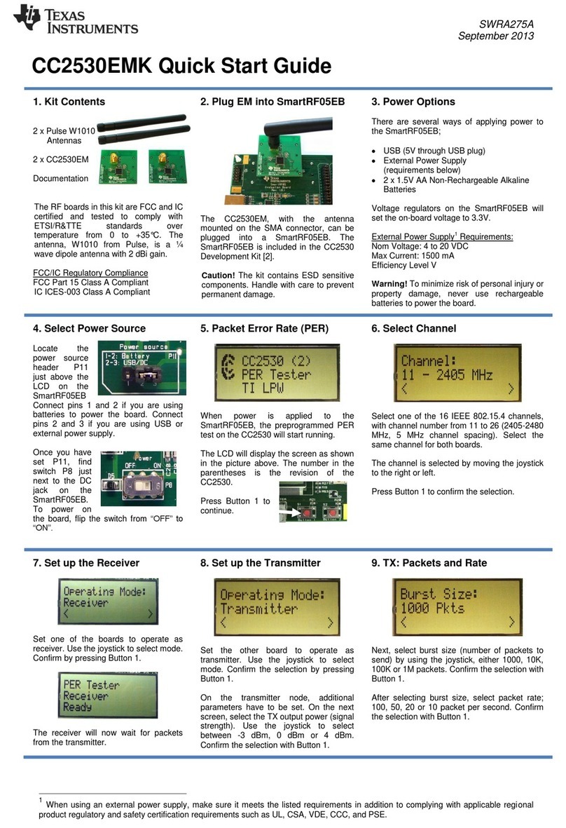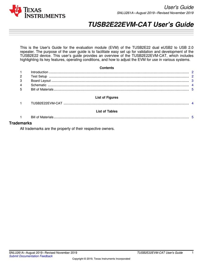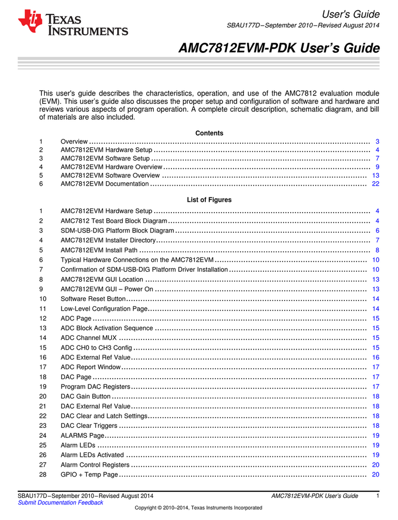
Table 1-3. EVM Shunt and Switch Installation (continued)
Shunt Description BQ25792/6/8 Setting
JP11 USB Micro B input D+ connection to charger D+ pin. Connect this when the input source
detection and handshake features are desired.
Installed
JP12 REGN to TS resistor divider network connection. This must remain connected. Installed
JP13 ILIM_HIZ pin setting for 500 mA. Connect to set the external input current limit setting to
500mA
Not Installed
JP14 ILIM_HIZ pin setting for 1.5 A. Install shunt to set the external input current limit setting to 1.5
A.
Installed
JP15 Thermistor COOL temperature setting. Connect jumper to simulate charger entering TCOOL
(T1-T2) temperature region.
Not Installed
JP16 Thermistor COLD temperature setting. Connect jumper to simulate charger entering TCOLD
(<T1) temperature region.
Not Installed
JP17 CE pin connection to ground to enable charging. When removed, CE pin will pull up to disable
charge
Installed
JP18 Thermistor NORMAL temperature setting. Connect jumper to simulate charger entering
TNORMAL (T2-T3) temperature region. Keep connected when testing other thermistor
temperature settings (JP17 - TCOOL, JP18 - TCOLD, JP21 - TWARM, JP22 - THOT).
Remove this jumper whenever using an externally connected thermistor.
Installed
JP19 Thermistor WARM temperature setting. Connect jumper to simulate charger entering TWARM
(T3-T5) temperature region.
Not Installed
JP20 Thermistor HOT temperature setting. Connect jumper to simulate charger entering THOT
(>T5) temperature region.
Not Installed
JP21 ILIM_HIZ pin setting for HIZ mode. Connect to enter the charger high impedance (HIZ) mode
to disable the converter
Not Installed
JP22 PROG pin setting for 1S, 1.5 MHz. Connect to configure charger default setting to 1S charge
regulation voltage, 2 A charging current, and 1.5 MHz switching frequency
Not Installed
JP23 PROG pin setting for 1S, 750 kHz. Connect to configure charger default setting to 1S charge
regulation voltage, 2 A charging current, and 750 kHz switching frequency
Not Installed
JP24 PROG pin setting for 2S, 1.5 MHz. Connect to configure charger default setting to 2S charge
regulation voltage, 2 A charging current, and 1.5 MHz switching frequency
Installed
JP25 PROG pin setting for 2S, 750 kHz. Connect to configure charger default setting to 2S charge
regulation voltage, 2 A charging current, and 750 kHz switching frequency
Not Installed
JP26 PROG pin setting for 3S, 1.5 MHz. Connect to configure charger default setting to 3S charge
regulation voltage, 1 A charging current, and 1.5 MHz switching frequency
Not Installed
JP27 PROG pin setting for 3S, 750 kHz. Connect to configure charger default setting to 3S charge
regulation voltage, 1 A charging current, and 750 kHz switching frequency
Not Installed
JP28 PROG pin setting for 4S, 1.5 MHz. Connect to configure charger default setting to 4S charge
regulation voltage, 1 A charging current, and 1.5 MHz switching frequency
Not Installed
JP29 PROG pin setting for 4S, 750 kHz. Connect to configure charger default setting to 4S charge
regulation voltage, 1 A charging current, and 750 kHz switching frequency
Not Installed
JP30 Input connection for onboard PULLUP rail LDO. Connect to power onboard 3.3V pullup rail.
LDO input will be connected via diode-OR between VBUS and BAT
Installed
JP31 EV2400 internal pullup to PULLUP connection. Connect to use EV2400 internal 3.3 V pullup to
drive the EVM PULLUP rail.
Not Installed
JP32 STAT pin LED indicator connection. This indicates the current charger Status Installed
JP33 USB2ANY internal pullup to PULLUP connection. Connect to use the USB2ANY internal 3.3 V
pullup to drive the EVM PULLUP rail
Not Installed
S1 QON control switch. Press to either exit Ship Mode or reset the System Power Default Off
www.ti.com Introduction
SLUUCB5E – JUNE 2020 – REVISED JULY 2022
Submit Document Feedback
BQ25792EVM, BQ25798EVM and BQ25798BKUPEVM (BMS034) Evaluation
Module
5
Copyright © 2022 Texas Instruments Incorporated
