User’s Guide
DRV8329AEVM User’s Guide
ABSTRACT
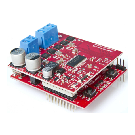
This document is provided with the DRV8329 customer evaluation module (EVM) as a supplement to the
DRV8329 data sheet (DRV8329 4.5-V to 60-V 1000/2000mA 3-phase gate driver). This User's Guide details the
implementation of the EVM and shows how to set up and power the board.
Note
The DRV8329AEVM comes automatically populated with and configured for the DRV8329A. It is also
compatible for the DRV8329B variants (see Section 4.4.1), but the user will need to replace the
DRV8329A with the DRV8329B for compatibility.
Table of Contents
1 Cautions and Warnings..........................................................................................................................................................3
2 Introduction.............................................................................................................................................................................4
3 Quick Start Guide....................................................................................................................................................................6
4 Hardware and Software Overview.........................................................................................................................................7
4.1 Hardware Connections Overview – DRV8329AEVM + LAUNCHXL-F280049C................................................................7
4.2 Connection Details............................................................................................................................................................. 7
4.3 LED Lights........................................................................................................................................................................10
4.4 DRV8329AEVM Configurability Switch Functions............................................................................................................11
4.5 Interfacing DRV8329AEVM and LAUNCHXL-F280049C LaunchPad............................................................................. 12
5 Hardware Setup.................................................................................................................................................................... 15
6 Firmware and GUI Application.............................................................................................................................................16
6.1 Connecting to the DRV8329AEVM-GUI...........................................................................................................................16
6.2 DRV8329x EVM GUI Quick Start Guide.......................................................................................................................... 17
6.3 Using the DRV8329AEVM-GUI........................................................................................................................................17
7 Schematics............................................................................................................................................................................19
7.1 DRV8329A/B....................................................................................................................................................................19
7.2 Status LEDs..................................................................................................................................................................... 19
7.3 LaunchPad Connectors and Connections........................................................................................................................20
7.4 Power Stage and MOSFETs............................................................................................................................................ 20
7.5 Main Supply Input............................................................................................................................................................ 21
7.6 Hall Sensor and Hall Power selection.............................................................................................................................. 21
7.7 Connectors, Selectors, and Analog Control Interface...................................................................................................... 22
7.8 Dead Time and CSA Gain Selection................................................................................................................................22
7.9 Voltage Sense and Protection..........................................................................................................................................23
List of Figures
Figure 2-1. DRV8329AEVM PCB Layout.....................................................................................................................................5
Figure 4-1. Major hardware blocks of the DRV8329AEVM..........................................................................................................7
Figure 4-2. Connections from motor to DRV8329AEVM............................................................................................................. 8
Figure 4-3. DRV8329AEVM on headers J1/J3 and J2/J4 of LaunchPad.................................................................................... 9
Figure 4-4. Micro-USB plugged into LaunchPad......................................................................................................................... 9
Figure 4-5. DRV8329AEVM LEDs.............................................................................................................................................10
Figure 4-6. User-adjustable jumpers, resistors, and switches on DRV8329AEVM................................................................... 12
Figure 6-1. DRV8329A_EVM_GUI and DRV8329B_EVM_GUI on the Gallery.........................................................................16
Figure 6-2. Hardware connected message................................................................................................................................16
Figure 6-3. DRV8329A_EVM_GUI defaults when connected....................................................................................................17
Figure 7-1. DRV8329A/B schematic..........................................................................................................................................19
Figure 7-2. Status LEDs schematic........................................................................................................................................... 19
www.ti.com Table of Contents
SLVUCF5 – MARCH 2022
Submit Document Feedback
DRV8329AEVM User’s Guide 1
Copyright © 2022 Texas Instruments Incorporated
