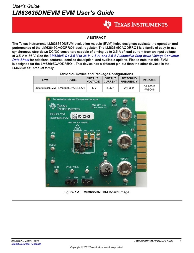
Table of Contents
1 Overview .................................................................................................................................................................................3
1.1 ADS9817EVM-PDK Features............................................................................................................................................ 3
2 Analog Interface......................................................................................................................................................................5
2.1 ADS9817 Device Connections...........................................................................................................................................5
2.2 Input SMA Connections..................................................................................................................................................... 6
3 Digital Interface.......................................................................................................................................................................7
4 Power Supplies....................................................................................................................................................................... 8
5 EVM Operation........................................................................................................................................................................ 9
5.1 ADS9817EVM Software Installation...................................................................................................................................9
5.2 USB Driver Installation..................................................................................................................................................... 10
5.3 Connecting the Hardware and Starting the Software.......................................................................................................12
5.4 Initial Required Setup on the Config Tab..........................................................................................................................13
5.5 Initial Required Setup on the Capture Tab....................................................................................................................... 14
5.6 Using the INL/DNL Tool....................................................................................................................................................15
6 Bill of Materials, Schematics, and Layout.......................................................................................................................... 16
6.1 Bill of Materials (BOM)..................................................................................................................................................... 16
6.2 Schematics.......................................................................................................................................................................18
6.3 Layout.............................................................................................................................................................................. 22
List of Figures
Figure 1-1. System Using FMC to VITA57 and FPGA Kit............................................................................................................3
Figure 1-2. System Using GUI and TSWDC155EVM..................................................................................................................4
Figure 1-3. ADS9817EVM Block Diagram...................................................................................................................................4
Figure 2-1. Connections to ADS9817.......................................................................................................................................... 5
Figure 2-2. Input SMA Connections Digital Interface...................................................................................................................6
Figure 3-1. Digital I/O...................................................................................................................................................................7
Figure 4-1. Power Entry and Regulators..................................................................................................................................... 8
Figure 5-1. Initial Software Installation.........................................................................................................................................9
Figure 5-2. Installation Process................................................................................................................................................. 10
Figure 5-3. Open Device Manager............................................................................................................................................ 10
Figure 5-4. Update Driver With Device Manager....................................................................................................................... 11
Figure 5-5. Connecting the Hardware........................................................................................................................................12
Figure 5-6. Start the Software GUI............................................................................................................................................ 12
Figure 5-7. Initial Required Setup on the Config Tab.................................................................................................................13
Figure 5-8. Initial Required Setup on the Capture Tab.............................................................................................................. 14
Figure 5-9. Using the INL/DNL Tool...........................................................................................................................................15
Figure 6-1. ADS9817 Device Connections................................................................................................................................ 18
Figure 6-2. SMA Input Signal Connections................................................................................................................................19
Figure 6-3. Digital Connector.....................................................................................................................................................20
Figure 6-4. Power Connections and Regulators........................................................................................................................21
Figure 6-5. ADS9817 PCB Layout Top......................................................................................................................................22
Figure 6-6. ADS9817 PCB Layout Bottom................................................................................................................................ 23
List of Tables
Table 1-1. Related Documentation.............................................................................................................................................. 3
Table 6-1. ADS9817EVM-PDK Bill of Materials.........................................................................................................................16
Trademarks
Microsoft® and Windows® are registered trademarks of Microsoft Corporation.
All trademarks are the property of their respective owners.
Table of Contents www.ti.com
2ADS9817EVM-PDK Evaluation Module SBAU416 – NOVEMBER 2022
Submit Document Feedback
Copyright © 2022 Texas Instruments Incorporated
