Figure 3-1. Applications Diagram................................................................................................................................................ 4
Figure 4-1. Interfacing to the EVM...............................................................................................................................................5
Figure 5-1. DS90UB960-Q1EVM Jumper and Switch Configuration...........................................................................................6
Figure 6-1. Power-over-Coax Network Compatible with DS90UB935-Q1 and DS90UB953-Q1.................................................7
Figure 6-2. Power-over-Coax Network Compatible with DS90UB913A-Q1, DS90UB933-Q1, DS90UB935-Q1, and
DS90UB953-Q1....................................................................................................................................................................... 8
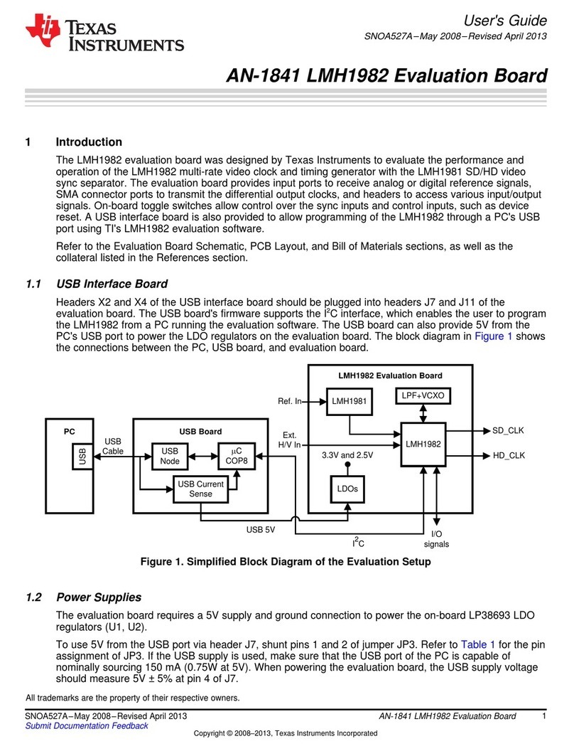
Figure 8-1. Launching ALP........................................................................................................................................................ 16
Figure 8-2. Initial ALP Screen....................................................................................................................................................16
Figure 8-3. Follow-up Screen.................................................................................................................................................... 17
Figure 8-4. ALP Information Tab................................................................................................................................................17
Figure 8-5. ALP Registers Tab...................................................................................................................................................18
Figure 8-6. ALP Device ID Selected.......................................................................................................................................... 18
Figure 8-7. ALP Device ID Expanded........................................................................................................................................19
Figure 8-8. ALP Scripting Tab....................................................................................................................................................20
Figure 9-1. USB2ANY Setup..................................................................................................................................................... 23
Figure 9-2. Remove Incorrect Profile.........................................................................................................................................23
Figure 9-3. Add Correct Profile.................................................................................................................................................. 24
Figure 9-4. Finish Setup............................................................................................................................................................ 24
Figure 9-5. ALP No Devices Error............................................................................................................................................. 25
Figure 9-6. Windows 7, ALP USB2ANY Driver..........................................................................................................................25
Figure 9-7. ALP in Demo Mode................................................................................................................................................. 26
Figure 9-8. ALP Preferences Menu........................................................................................................................................... 26
Figure 12-1. Typical Test Setup for Application......................................................................................................................... 27
Figure 12-2. Typical Test Setup for Evaluation.......................................................................................................................... 27
Figure 17-1. Top View Composite..............................................................................................................................................43
Figure 17-2. Layer 1: Top Signal Layer......................................................................................................................................43
Figure 17-3. Layer 2: GND 1 Layer........................................................................................................................................... 44
Figure 17-4. Layer 3: Inner Signal 1 Layer................................................................................................................................ 44
Figure 17-5. Layer 4: GND 2 Layer........................................................................................................................................... 45
Figure 17-6. Layer 5: GND 3 Layer........................................................................................................................................... 45
Figure 17-7. Layer 6: Inner Signal 2 Layer................................................................................................................................ 46
Figure 17-8. Layer 7: GND 4 Layer........................................................................................................................................... 46
Figure 17-9. Layer 8: Bottom Signal Layer................................................................................................................................ 47
Figure 17-10. Bottom Overlay....................................................................................................................................................47
List of Tables
Table 6-1. Power Supply..............................................................................................................................................................7
Table 6-2. Required PoC Network Updates for Compatibility to DS90UB913A-Q1 and DS90UB933-Q1 Serializers.................9
Table 6-3. Power-Over-Coax Power Supply Feed Configuration................................................................................................ 9
Table 6-4. MIPI CSI-2 (TX Port 0) Output Signals - J1 Pinout................................................................................................... 10
Table 6-5. MIPI CSI-2 (TX Port 1) Output Signals - J3 Pinout................................................................................................... 10
Table 6-6. MIPI CSI-2 Output Signals - J2 Pinout......................................................................................................................11
Table 6-7. FPD-Link III Signals.................................................................................................................................................. 12
Table 6-8. IDx I2C Device Address Select - J34........................................................................................................................ 12
Table 6-9. Primary I2C Interface Header - J4.............................................................................................................................12
Table 6-10. Secondary I2C Interface Header - J5...................................................................................................................... 12
Table 6-11. I2C VDDIO Interface Header - J30.......................................................................................................................... 13
Table 6-12. VDDIO Interface Header - J1..................................................................................................................................13
Table 6-13. GPIO Interface Header - J8.................................................................................................................................... 13
Table 6-14. CMLOUTP Output Signals......................................................................................................................................13
Table 6-15. Mode SW-DIP4 - S1 ...............................................................................................................................................13
Table 6-16. Control SW-DIP2 - SW1..........................................................................................................................................13
Table 6-17. LEDs....................................................................................................................................................................... 13
Table 15-1. BOM for DS90UB960-Q1EVM ...............................................................................................................................29
Table of Contents www.ti.com
2DS90UB960-Q1EVM User's Guide SNLU226B – FEBRUARY 2018 – REVISED APRIL 2021
Submit Document Feedback
Copyright © 2021 Texas Instruments Incorporated
