manuals.online logo
Brands
  1. Home
  2. •
  3. Brands
  4. •
  5. Texas Instruments
  6. •
  7. Motherboard
  8. •
  9. Texas Instruments TAS6422-Q1 User manual

Texas Instruments TAS6422-Q1 User manual

1
SLOU464A–March 2017–Revised October 2017
Submit Documentation Feedback Copyright © 2017, Texas Instruments Incorporated
TAS6422-Q1 Evaluation Module
User's Guide
SLOU464A–March 2017–Revised October 2017
TAS6422-Q1 Evaluation Module
This manual describes the operations of the TAS6422Q1EVM. The TAS6422Q1EVM is a stand-alone
EVM. The PurePath™ Control Console 3 GUI (PPC3) is used to initialize and operate the EVM. The main
topics of this document are:
• Hardware implementation and descriptions
• Software implementation and descriptions
• TAS6422 EVM operations (hardware and software)
Required equipment and accessories:
1. TAS6422 EVM
2. USB A male to micro B male cable
3. Power Supply Unit (PSU) up to 26.4 V, > 6 A capable, if J12 is removed and 12 V is provided.
If J12 is in, limit the input voltage to 18 V.
4. 1-4 resistive loads or speaker loads
5. 2-6 pair of wires stripped both ends
6. 2-mm slotted screwdriver
7. Optical audio source (optional)
8. Optical SPDIF cable (optional)
9. Desktop or laptop PC with Microsoft®Windows®7 operating system
Contents
1 Hardware Overview.......................................................................................................... 2
2 Hardware Overview.......................................................................................................... 3
3 Software Overview........................................................................................................... 4
4 Board Layouts, Bill of Materials, and Schematic....................................................................... 20
List of Tables
1 TAS6422Q1EVM Bill of Materials........................................................................................ 24
Trademarks
PurePath is a trademark of Texas Instruments.
Microsoft, Windows are registered trademarks of Microsoft Corporation.
All other trademarks are the property of their respective owners.
Hardware Overview
www.ti.com
2SLOU464A–March 2017–Revised October 2017
Submit Documentation Feedback
Copyright © 2017, Texas Instruments Incorporated
TAS6422-Q1 Evaluation Module
1 Hardware Overview
1.1 TAS6422 Evaluation Module Description
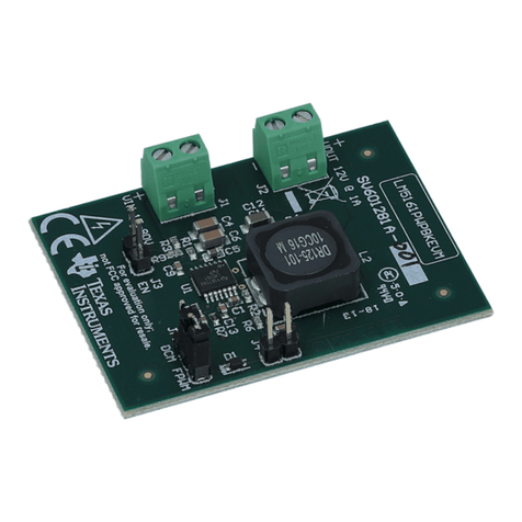
The TAS6422-Q1 EVM is a stand-alone EVM. It has single power supply input, USB control via PurePath
Control Console 3 (PPC3) and two digital (I2S) audio input options. See the EVM block diagram in
Figure 1.
Figure 1. TAS6422-Q1 EVM
www.ti.com
Hardware Overview
3
SLOU464A–March 2017–Revised October 2017
Submit Documentation Feedback Copyright © 2017, Texas Instruments Incorporated
TAS6422-Q1 Evaluation Module
The block diagram shows the TAS6422 EVM signal flow.
Figure 2. EVM Block Diagram
2 Hardware Overview
2.1 TAS6422 Evaluation Module Functions
• The EVM only needs single supply to operate
• The VBAT can be separated for PVDD operation higher than 18 V
• Two audio sources can be selected readily
1. If USB is selected, Windows Media Player can be used to stream audio.
2. If optical is selected, an optical source such as DVD player can be used to stream audio.
3. If external digital audio source such as Programmable Serial Interface Adapter (PSIA) from Audio
Precision, series resistors on I2S signals can be removed and jumpers can be used to insert
external I2S signals.
• There are three switches
1. SPDIF power switch turns on and off optical to I2S converter.
2. Standby switch puts the device on or out of standby.
3. Mute switch stops or starts PWM modulation.
• USB connection also uses as a controller via I2C. The Pure Path Console 3 is the User Interface
sending I2C commands to the device. PPC3 will be discussed in a later section.
Software Overview
www.ti.com
4SLOU464A–March 2017–Revised October 2017
Submit Documentation Feedback
Copyright © 2017, Texas Instruments Incorporated
TAS6422-Q1 Evaluation Module
3 Software Overview
3.1 PurePath™ Console 3 (PPC3) Access and Description
The PPC3 is a server-based tool. Access can be requested on
http://www.ti.com/tool/PUREPATHCONSOLE.
Once approval is given, go to www.ti.com/mysecuresoftware to download the software. After login, the
user will see this web page with a similar list of software products available for download.
Figure 3. PPC3 Download Window
www.ti.com
Software Overview
5
SLOU464A–March 2017–Revised October 2017
Submit Documentation Feedback Copyright © 2017, Texas Instruments Incorporated
TAS6422-Q1 Evaluation Module
Run the installation program. Also download the PPC3 User Manual (SLOU408) for further instructions.
The following window is displayed when first running PPC3.
Figure 4. PPC3 Window
When the window in Figure 4 is displayed, click on “sign in” to see TAS6422 EVM application. All of the
apps shown below may not be displayed for the user.
Software Overview
www.ti.com
6SLOU464A–March 2017–Revised October 2017
Submit Documentation Feedback
Copyright © 2017, Texas Instruments Incorporated
TAS6422-Q1 Evaluation Module
Click on TAS6422 App box to download TAS6422 application. Installation window will pop up, then click
“Install”.
TAS6422 EVM box will appear in “Installed EVM Apps” section, see Figure 5. Click on TAS6422 box to
launch TAS6422 App.
Figure 5. Available Apps Window
www.ti.com
Software Overview
7
SLOU464A–March 2017–Revised October 2017
Submit Documentation Feedback Copyright © 2017, Texas Instruments Incorporated
TAS6422-Q1 Evaluation Module
3.2 PurePath™ Console 3 – TAS6422 EVM Home Window
When the TAS6422 EVM PPC3 is launched, the Home Window is shown. If the EVM is powered on and
the USB is connected to the PC, the Home Window will display “Connect” box in the bottom right hand
corner. If the EVM is not powered on or the USB is not connected, only “TAS6422 EVM – Offline” is
displayed.
Figure 6 shows the TAS6422 installed application.
Figure 6. PPC3 Window
Software Overview
www.ti.com
8SLOU464A–March 2017–Revised October 2017
Submit Documentation Feedback
Copyright © 2017, Texas Instruments Incorporated
TAS6422-Q1 Evaluation Module
There are three windows available with the TAS6422 EVM PPC3: Home Window, Register Map Window
and Device Monitor and Control Window.
Figure 7. TAS6422 EVM Home Window
www.ti.com
Software Overview
9
SLOU464A–March 2017–Revised October 2017
Submit Documentation Feedback Copyright © 2017, Texas Instruments Incorporated
TAS6422-Q1 Evaluation Module
3.3 PurePath™ Console 3 – TAS6422 EVM Register Map Window
When click on Register Map Box on the Home Window, the Register Map Window is displayed. The
Register Map indicates the current setting of all the registers in TAS6422.
Figure 8. TAS6422 EVM Register Map Window
Software Overview
www.ti.com
10 SLOU464A–March 2017–Revised October 2017
Submit Documentation Feedback
Copyright © 2017, Texas Instruments Incorporated
TAS6422-Q1 Evaluation Module
3.4 PurePath™ Console 3 – TAS6422 EVM Monitor and Control Window
When click on Device Monitor and Control Box on the Home Window, the Device Monitor and Control
Window is displayed. The Register Map indicates the current setting of all the registers in TAS6422.
Figure 9. TAS6422 EVM Device Monitor and Control Window
www.ti.com
Software Overview
11
SLOU464A–March 2017–Revised October 2017
Submit Documentation Feedback Copyright © 2017, Texas Instruments Incorporated
TAS6422-Q1 Evaluation Module
3.5 TAS6422 EVM Start Up
This section describes the TAS6422 start-up procedure. Have the equipment and accessories listed on
the first page of this document available.
3.5.1 TAS6422 EVM Setup
Hardware and software connections:
• Desk top or laptop PC running Windows 7. Open PPC3 GUI.
• Connect 14.4 VDC PSU to TAS6422 EVM
• Connect speakers or resistive loads to TAS6422 EVM
• Connect USB micro cable from PC to the EVM
• Set the switches (SPDIF, STANDBY, MUTE) to up positions
• Turn on the PSU
• Audio source: This can be a DVD player with optical SPDIF cable or Windows Media Player from PC
• At this point, 3.3 V LED, USB-LOCK LED and SPDIF-LOCK LED (if optical SPDIF is used) are on.
• If the SPDIF LED is not on, the default I2S input is the USB audio source.
• On the PPC3 window, launch TAS6422 EVM application
• The audio can be streamed now to the speakers. Go to the GUI and click on “Device Monitor &
Control” box. Click on play button located on the top right of the window.
• The following sections describe in detail the register settings of TAS6422.
Figure 10. TAS6422 EVM Connection
Software Overview
www.ti.com
12 SLOU464A–March 2017–Revised October 2017
Submit Documentation Feedback
Copyright © 2017, Texas Instruments Incorporated
TAS6422-Q1 Evaluation Module
3.5.2 TAS6422 Settings on Device Monitor and Control Window
The TAS6422 Register Map window is for reference. Most of the register settings are done on the Device
Monitor and Control window
Click on “CONNECT” button on the bottom left corner of the TAS6422 EVM application window, see
Figure 11. The LED next to the TAS6422 EVM changes from gray to green and the “CONNECT” button
changes to “DISCONNECT” button.
Click on the TAS6422 Device Monitor and Control box. The following window is displayed.
Figure 11. Device Monitor and Control Window
This window has 6 major sections: global control section, channel control section, other control section,
faults and warnings section, AC load diagnostics section and DC load diagnostics section.
3.5.2.1 Global Control Section
The Hi-z, Mute and Unmute buttons with the gray background controls all 4 channels at the same time.
When Hi-z is selected, all 4 channels are put in Hi-z. The display for each channel in the channel control
section will reflect these buttons selections.
The Mute Pin button is the GPIO pin controlling the mute function of the device.
The Standby button is the GPIO pin controlling the standby function of the device.
The Reset button is software reset. This will put the device back in default settings.
Figure 12. Global Control Section
www.ti.com
Software Overview
13
SLOU464A–March 2017–Revised October 2017
Submit Documentation Feedback Copyright © 2017, Texas Instruments Incorporated
TAS6422-Q1 Evaluation Module
3.5.2.2 Channel Control Section
Each channel has the same setting selections: Hi-z, Mute, Unmute, Volume, Line-out mode and Speaker
mode.
The drop down menu allows user to select either Hi-z, Mute or Unmute state of each channel.
The volume slide controls the digital gain of each channel.
The default setting for each channel is speaker mode. If line-out is used, select Line Output button.
Figure 13. Channel Control Section
3.5.2.3 Miscellaneous Control Section
There are miscellaneous settings that are available on the GUI for easy access.
OSR is oversampling bit. For lower idle noise 64X OSR is set as default. For wider bandwidth, 128X OSR
can be used. 64X OSR is recommended.
TAS6422 supports parallel Bridge-Tied Load. Channels 1 and 2 can be one PBTL channel and channels 3
and 4 can be the other. Before setting a set of channels to PBTL mode, connect the (+) terminals as PBTL
channel (+) and the (-) terminals as PBTL channel (-). Then connect the speaker (+) to the PBTL channel
(+) and connect the speaker (-) to the PBTL channel (-).
The over-current has two levels. The lower level is 1. The default is level 2. When running at lower output
current, OC level can be set to 1. I2S and TDM are automatically detected. Use the pull down menu from
“Input Format” box to manually select the audio format.
If sampling frequency is greater than 48 kHz, select 96 kHz from the “Input FS” pull down.
Over-temperature warning can be programmable, use the pull down menu to choose the OTW
temperature. The default setting is 120°C.
The output switching frequency (FSW) or Pulse Width Modulation frequency (PWM) is set at 2.1 MHz. The
pull-down menu on the PWM FRQ box is used to choose a lower FSW. LC value should be adjusted
when FSW is changed.
The offset phase for each channel is set at 45 degrees. This helps lower the ripple current on the power
supply as not all the channels switch at the same time. To choose a different phase offset, use the pull-
down menu on the “Phase” box.
There are four gain settings in TAS6422: low, normal, high and maximum. The default setting is high.
However, the recommended setting is normal for lower noise performance for driving speakers at
14.4 VDC. The gain setting is selectable via the drop down menu in the ”Gain” box.
The volume slew rate is measured with sampling frequency. The default setting is 1 period of sampling
frequency (FSYNC or FS). This rate is selectable from 1 to 8 sampling periods with the drop down menu
under “Vol Rate” box.
Software Overview
www.ti.com
14 SLOU464A–March 2017–Revised October 2017
Submit Documentation Feedback
Copyright © 2017, Texas Instruments Incorporated
TAS6422-Q1 Evaluation Module
Figure 14. Other Control Section
3.5.2.4 Faults and Warnings Section
The top right buttons on this box serve as controlling and monitoring faults.
Clip enable route the clip detection bit to the warning pin. This is displayed as yellow LED on the EVM.
Thermal enable route the over-temperature warning bit to the warning pin. This is display as the same
yellow LED on the EVM.
Clear button clears all the faults and warnings.
Read button manually read the faults and warnings.
Figure 15. Faults and Warnings Section
www.ti.com
Software Overview
15
SLOU464A–March 2017–Revised October 2017
Submit Documentation Feedback Copyright © 2017, Texas Instruments Incorporated
TAS6422-Q1 Evaluation Module
3.5.2.5 AC Load Diagnostics Section
AC load diagnostics report speaker impedance and phase. The diagnostics can be performed with one or
all four channels.
Select the correct output impedance and click start. Follow the pop up instructions to complete the load
diagnostics run.
NOTE: Make sure to set the digital input to 0 dBFS (100% full-scale). If the sine wave is provided
from the USB audio, turn the audio media volume and PC sound card volume to maximum.
Click on the “flip” icon located on the top right of the AC load diagnostics box to see the results.
Figure 16. AC Load Diagnostics Section
3.5.2.6 DC Load Diagnostics Section
The DC load diagnostics report if a channel is short to power, short to ground, short to load or open.
Select the impedance of the load from 0.5 to 5 Ω. Click start and then click the “flip” on the top right of the
box to view results.
If a channel is selected as a line-out, click on “LO ENA LD” to enable line-out load diagnostics.
“Retry” box is used when DC load diagnostics are run more than one time.
DC load diagnostics can be aborted by click on the “Abort LD” box.
Figure 17. DC Load Diagnostics Section
Software Overview
www.ti.com
16 SLOU464A–March 2017–Revised October 2017
Submit Documentation Feedback
Copyright © 2017, Texas Instruments Incorporated
TAS6422-Q1 Evaluation Module
3.5.3 TAS6422 Settings on Register Map Window
The register map can be sorted either alphabetically or numerically (register number).
Figure 18. Register Map Window
www.ti.com
Software Overview
17
SLOU464A–March 2017–Revised October 2017
Submit Documentation Feedback Copyright © 2017, Texas Instruments Incorporated
TAS6422-Q1 Evaluation Module
When a register is selected, the hex value along with the individual bit value is displayed. The name and
description for each bit are shown to the right in the "Fields" box.
Figure 19. Register Map Window - Expanding
Double click on any bit, the bit will change state. This state is executed at the end of the click.
Software Overview
www.ti.com
18 SLOU464A–March 2017–Revised October 2017
Submit Documentation Feedback
Copyright © 2017, Texas Instruments Incorporated
TAS6422-Q1 Evaluation Module
3.5.4 I2C Window
The PPC3 has an I2C monitor and also configuration program options.
When this window is first open, the round button is green. To record I2C commands, click on this button
and it will turn red. The recording can be saved for later used by clicking the save icon.
The I2C commands can also be copied to clip board by clicking the icon next to trash bin icon.
Figure 20. I2C Window – I2C Logging
www.ti.com
Software Overview
19
SLOU464A–March 2017–Revised October 2017
Submit Documentation Feedback Copyright © 2017, Texas Instruments Incorporated
TAS6422-Q1 Evaluation Module
A set of I2C commands can be loaded and executed from this window. On the top right corner, click on
“I/O” button to display the above window. Write I2C commands here or open an existing *.cfg file then
click “Execute” button on the bottom left corner. The I2C commands are sent to the device when the
“Execute” button is pressed.
Figure 21. I2C Window – Sending I2C Commands
Board Layouts, Bill of Materials, and Schematic
www.ti.com
20 SLOU464A–March 2017–Revised October 2017
Submit Documentation Feedback
Copyright © 2017, Texas Instruments Incorporated
TAS6422-Q1 Evaluation Module
4 Board Layouts, Bill of Materials, and Schematic
4.1 TAS6422 EVM Layouts
Figure 22. TAS6422 EVM Top

This manual suits for next models

1

Other Texas Instruments Motherboard manuals
Texas Instruments TPS62110EVM-101 User manual

Texas Instruments

Texas Instruments TPS62110EVM-101 User manual

Texas Instruments TPS65261EVM-650 User manual

Texas Instruments

Texas Instruments TPS65261EVM-650 User manual

Texas Instruments TPS62A0 PEVM-018 Series User manual

Texas Instruments

Texas Instruments TPS62A0 PEVM-018 Series User manual

Texas Instruments DLP3021LEQ1EVM User manual

Texas Instruments

Texas Instruments DLP3021LEQ1EVM User manual

Texas Instruments TPS62065EVM User manual

Texas Instruments

Texas Instruments TPS62065EVM User manual

Texas Instruments TPS65217EVM User manual

Texas Instruments

Texas Instruments TPS65217EVM User manual

Texas Instruments TA 5 42EVM-K Series User manual

Texas Instruments

Texas Instruments TA 5 42EVM-K Series User manual

Texas Instruments INA219EVM User manual

Texas Instruments

Texas Instruments INA219EVM User manual

Texas Instruments TMP104EVM User manual

Texas Instruments

Texas Instruments TMP104EVM User manual

Texas Instruments DAC53701EVM User manual

Texas Instruments

Texas Instruments DAC53701EVM User manual

Texas Instruments CC120 Series User manual

Texas Instruments

Texas Instruments CC120 Series User manual

Texas Instruments TPS652353 User manual

Texas Instruments

Texas Instruments TPS652353 User manual

Texas Instruments SimpleLink CC2650 User manual

Texas Instruments

Texas Instruments SimpleLink CC2650 User manual

Texas Instruments TLC6983 User manual

Texas Instruments

Texas Instruments TLC6983 User manual

Texas Instruments TUSB216IEVM User manual

Texas Instruments

Texas Instruments TUSB216IEVM User manual

Texas Instruments DRV8329AEVM User manual

Texas Instruments

Texas Instruments DRV8329AEVM User manual

Texas Instruments TPS26600-02EVM User manual

Texas Instruments

Texas Instruments TPS26600-02EVM User manual

Texas Instruments TPA3132D2EVM User manual

Texas Instruments

Texas Instruments TPA3132D2EVM User manual

Texas Instruments EK-LM4F232 User manual

Texas Instruments

Texas Instruments EK-LM4F232 User manual

Texas Instruments bq76200 User manual

Texas Instruments

Texas Instruments bq76200 User manual

Texas Instruments ADS7056EVM User manual

Texas Instruments

Texas Instruments ADS7056EVM User manual

Texas Instruments TAS3208EVM User manual

Texas Instruments

Texas Instruments TAS3208EVM User manual

Texas Instruments BoosterPack BOOST-ADS7042 User manual

Texas Instruments

Texas Instruments BoosterPack BOOST-ADS7042 User manual

Texas Instruments ADCx140EVM-PDK Series User manual

Texas Instruments

Texas Instruments ADCx140EVM-PDK Series User manual

Popular Motherboard manuals by other brands

ASROCK H610TM-ITX manual

ASROCK

ASROCK H610TM-ITX manual

Joy-it RS232-Shield quick start guide

Joy-it

Joy-it RS232-Shield quick start guide

COBHAM GR716-BOARD user manual

COBHAM

COBHAM GR716-BOARD user manual

Maxim MAX2741 General description

Maxim

Maxim MAX2741 General description

VIA Technologies VAB-820 quick start guide

VIA Technologies

VIA Technologies VAB-820 quick start guide

IEI Technology WAFER-4823 user manual

IEI Technology

IEI Technology WAFER-4823 user manual

Shuttle FB51 manual

Shuttle

Shuttle FB51 manual

Gigabyte GA-8I915P Dual Graphic manual

Gigabyte

Gigabyte GA-8I915P Dual Graphic manual

Biostar M7 VKD Engineering validation test report

Biostar

Biostar M7 VKD Engineering validation test report

MSI Intel 500 Series user guide

MSI

MSI Intel 500 Series user guide

MSI B450 GAMING PLUS MAX quick start

MSI

MSI B450 GAMING PLUS MAX quick start

TYAN Tiger MP S2460 user manual

TYAN

TYAN Tiger MP S2460 user manual

Avalue Technology ECM-CFS user manual

Avalue Technology

Avalue Technology ECM-CFS user manual

Gigabyte GA-EX58-UD5 user manual

Gigabyte

Gigabyte GA-EX58-UD5 user manual

Analog Devices ADSP-21262 EZ-KIT Lite manual

Analog Devices

Analog Devices ADSP-21262 EZ-KIT Lite manual

EVOC EPE-1814V2NAR user manual

EVOC

EVOC EPE-1814V2NAR user manual

PCchips M757MR manual

PCchips

PCchips M757MR manual

AXIOMTEK PICO300 user manual

AXIOMTEK

AXIOMTEK PICO300 user manual

manuals.online logo
manuals.online logoBrands
  • About & Mission
  • Contact us
  • Privacy Policy
  • Terms and Conditions

Copyright 2025 Manuals.Online. All Rights Reserved.