1
SLOU479A–October 2017–Revised December 2017
Submit Documentation Feedback Copyright © 2017, Texas Instruments Incorporated
TPA6404-Q1 Evaluation Module
User's Guide
SLOU479A–October 2017–Revised December 2017
TPA6404-Q1 Evaluation Module
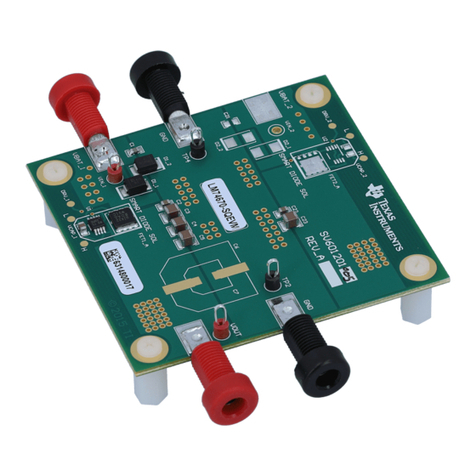
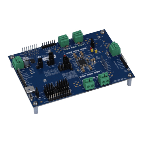
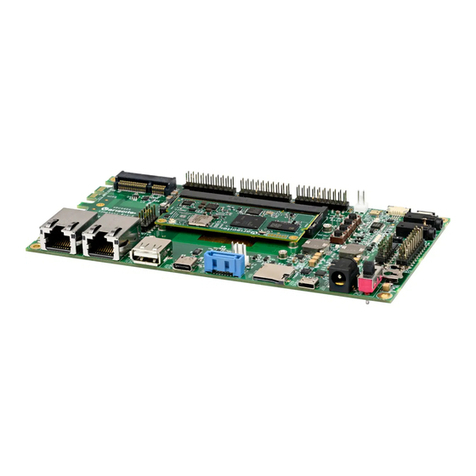
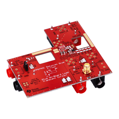
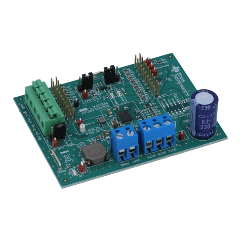
This manual describes the operations of the TPA6404Q1E2EVM. The TPA6404Q1E2EVM is a stand-
alone EVM. The PurePath™ Control Console 3 GUI (PPC3) is used to initialize and operate the EVM. The
main topics of this document are:
• Hardware implementation and descriptions
• Software implementation and descriptions
• TPA6404 EVM operations (hardware and software)
Required equipment and accessories:
1. TPA6404 EVM
2. USB A male to micro B male cable
3. Power Supply Unit (PSU) up to 18 V, 6-A capable
4. 1–4 resistive loads or speaker loads
5. 8 pairs of wires stripped both ends
6. 2-mm slotted screwdriver
7. Desktop or laptop PC with Microsoft®Windows®7 OS
8. Access to the internet for downloading software
Contents
1 Hardware Overview.......................................................................................................... 2
2 Software Overview........................................................................................................... 4
3 TPA6404 EVM Start Up..................................................................................................... 9
4 Board Layouts, Bill of Materials, and Schematic....................................................................... 16
List of Figures
1 TPA6404Q1 EVM............................................................................................................ 2
2 EVM Block Diagram......................................................................................................... 3
3 PPC3 Download Window................................................................................................... 4
4 PPC3 Window................................................................................................................ 5
5 Available Apps Window..................................................................................................... 5
6 TPA6404 EVM Home Window............................................................................................. 6
7 TPA6404 EVM Register Map Window.................................................................................... 7
8 TPA6404 EVM Device Monitor & Control Window...................................................................... 8
9 TPA6404 EVM Connections ............................................................................................... 9
10 Device Monitor & Control Window ....................................................................................... 10
11 Global Control Section..................................................................................................... 10
12 Channel Control Section .................................................................................................. 11
13 Miscellaneous Control Section ........................................................................................... 11
14 Faults / Warnings Section................................................................................................. 12
15 AC Load Diagnostics Section............................................................................................. 12
16 DC Load Diagnostics Section ............................................................................................ 13
17 Register Map Window ..................................................................................................... 13
18 I2C Window – I2C Logging ............................................................................................... 14
