User’s Guide
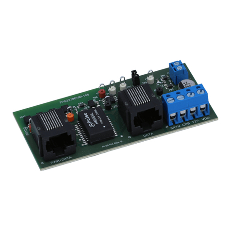
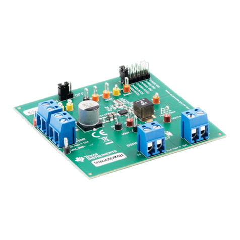
TPS2661EVM: Evaluation Module for TPS2661x
Current-Loop Protector
ABSTRACT
This user’s guide describes the evaluation module (EVM) for the Texas instruments TPS2661x current-loop
protector. The document provides EVM configuration information and test setup details for evaluating the
TPS26610 and TPS26612 devices. The EVM schematic, board layout, and bill of materials (BOM) are also
included.
Note
The TPS26611, TPS26613 and TPS26614 devices can also be evaluated on this EVM by replacing
the TPS26610 (U1) device.
Table of Contents
1 Introduction.............................................................................................................................................................................2
2 Description.............................................................................................................................................................................. 3
3 Schematic................................................................................................................................................................................4
4 General Configurations..........................................................................................................................................................5
5 Test Setup and Procedures....................................................................................................................................................7
6 EVAL Board Assembly Drawings and Layout Guidelines................................................................................................ 22
7 Bill Of Materials (BoM)..........................................................................................................................................................24
8 Revision History................................................................................................................................................................... 26
List of Figures
Figure 3-1. TPS2661EVM eFuse Evaluation Board Schematic.................................................................................................. 4
Figure 5-1. TPS2661EVM Setup With Test Equipment............................................................................................................... 7
Figure 5-2. Current Limit Behavior of TPS26610 for IOUT > 2 × IOLWith MODE = 180 kΩ ......................................................... 8
Figure 5-3. Current Limit Behavior of TPS26610 for IOUT > 2 × IOL With MODE = 180 kΩ (Zoomed).........................................9
Figure 5-4. TPS26610 Response During Recovery From Overload Fault.................................................................................. 9
Figure 5-5. Output Short-Circuit Response of TPS26610 Device............................................................................................. 10
Figure 5-6. Output Short-Circuit Response of TPS26610 Device (Zoomed)............................................................................. 11
Figure 5-7. Input Undervoltage Protection Response of TPS26610 Device..............................................................................12
Figure 5-8. Output Undervoltage Protection Response of TPS26610 Device...........................................................................13
Figure 5-9. Output Overvoltage Protection Response of TPS26610 Device.............................................................................14
Figure 5-10. Current-Limit Behavior of TPS26612.................................................................................................................... 15
Figure 5-11. Current-Limit Behavior of TPS26612 Under Sustained Overload......................................................................... 16
Figure 5-12. Current Limit Behavior of TPS26613 for VIN < –Vs ...............................................................................................17
Figure 5-13. IEC61000-4-5 (+1 kV, 42 Ω) Signal Line Surge Immunity With TVS3301 at Input of CH1....................................18
Figure 5-14. IEC61000-4-5 (–1 kV, 42 Ω) Signal Line Surge Immunity With TVS3301 at Input of CH1....................................19
Figure 5-15. IEC61000-4-5 (+1 kV, 42 Ω) Signal Line Surge Immunity With TVS3301 at Output of CH2.................................20
Figure 5-16. IEC61000-4-5 (–1 kV, 42 Ω) Signal Line Surge Immunity With TVS3301 at Output of CH2.................................21
Figure 6-1. TPS2661EVM Board Assembly.............................................................................................................................. 22
Figure 6-2. TPS2661EVM Board Top Layer.............................................................................................................................. 22
Figure 6-3. TPS2661EVM Board Bottom Layer.........................................................................................................................23
List of Tables
Table 2-1. TPS2661EVM eFuse Evaluation Board Options and Setting..................................................................................... 3
Table 4-1. Input and Output Connector Functionality.................................................................................................................. 5
Table 4-2. Test Points Description............................................................................................................................................... 5
www.ti.com Table of Contents
SLVUBX8B – OCTOBER 2020 – REVISED DECEMBER 2021
Submit Document Feedback
TPS2661EVM: Evaluation Module for TPS2661x
Current-Loop Protector
1
Copyright © 2021 Texas Instruments Incorporated
