User’s Guide
TPSM8D6C24 2-Phase Power Module Evaluation Module
User's Guide
ABSTRACT
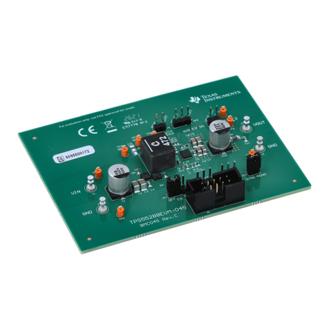
This user's guide describes the characteristics, operation, and use of the TPSM8D6C24EVM-2PH evaluation
module (EVM). In addition, the user's guide includes test information, descriptions, and results. A complete
schematic diagram, printed circuit board layouts, and bill of materials are also included in this document.
Table of Contents
1 Description.............................................................................................................................................................................. 3
1.1 Before You Begin............................................................................................................................................................... 3
1.2 Features............................................................................................................................................................................. 3
2 Electrical Performance Specifications................................................................................................................................. 4
3 Schematic................................................................................................................................................................................5
4 Test Setup................................................................................................................................................................................6
4.1 Test and Configuration Software........................................................................................................................................ 6
4.2 Test Equipment.................................................................................................................................................................. 6
4.3 List of Test Points, Jumpers, and Connectors....................................................................................................................7
4.4 Evaluating Split Rail Input.................................................................................................................................................. 8
5 EVM Configuration Using the Fusion GUI............................................................................................................................8
5.1 Configuration Procedure.................................................................................................................................................... 8
6 Test Procedure........................................................................................................................................................................ 8
6.1 Line and Load Regulation and Efficiency Measurement Procedure.................................................................................. 8
6.2 Efficiency Measurement Test Points.................................................................................................................................. 9
6.3 Control Loop Gain and Phase Measurement Procedure................................................................................................... 9
7 Performance Data and Typical Characteristic Curves...................................................................................................... 10
7.1 Efficiency..........................................................................................................................................................................10
7.2 Load Regulation............................................................................................................................................................... 10
7.3 Line Regulation.................................................................................................................................................................11
7.4 Transient Response......................................................................................................................................................... 11
7.5 Control Loop Bode Plot.................................................................................................................................................... 12
7.6 Output Ripple................................................................................................................................................................... 12
7.7 Control On........................................................................................................................................................................13
7.8 Control Off........................................................................................................................................................................14
7.9 Thermal Image................................................................................................................................................................. 15
8 EVM Assembly Drawing and PCB Layout.......................................................................................................................... 16
9 Bill of Materials..................................................................................................................................................................... 19
10 Using the Fusion GUI......................................................................................................................................................... 22
10.1 Opening the Fusion GUI................................................................................................................................................ 22
10.2 General Settings............................................................................................................................................................ 23
10.3 Changing ON_OFF_CONFIG........................................................................................................................................ 23
10.4 Pop-Up for Some Commands While Conversion is Enabled......................................................................................... 25
10.5 SMBALERT# Mask........................................................................................................................................................ 26
10.6 Device Info..................................................................................................................................................................... 27
10.7 Phase Commands..........................................................................................................................................................28
10.8 All Config........................................................................................................................................................................29
10.9 Pin Strapping..................................................................................................................................................................30
10.10 Monitor......................................................................................................................................................................... 31
10.11 Status........................................................................................................................................................................... 32
11 Revision History..................................................................................................................................................................32
www.ti.com Table of Contents
SLUUCL8A – DECEMBER 2021 – REVISED FEBRUARY 2022
Submit Document Feedback
TPSM8D6C24 2-Phase Power Module Evaluation Module User's Guide 1
Copyright © 2022 Texas Instruments Incorporated
