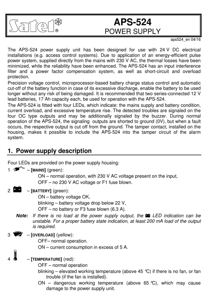
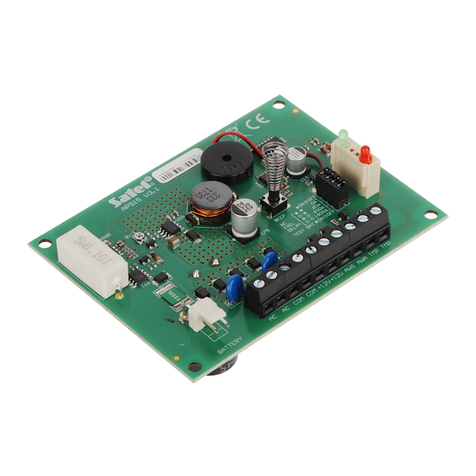
Satel APS-412 User manual

APS-412
Power supply
EN
Firmware version 1.02 aps-412_en 08/22
SATEL sp. z o.o. •ul. Budowlanych 66 • 80-298 Gdańsk • POLAND
tel. +48 58 320 94 00
www.satel.eu

IMPORTANT
The device should be installed by qualified personnel.
Prior to installation, please read carefully this manual in order to avoid mistakes that can lead
to malfunction or even damage to the equipment.
Changes, modifications or repairs not authorized by the manufacturer shall void your rights
under the warranty.
SATEL aims to continually improve the quality of its products, which may result in changes in
their technical specifications and software. Current information about the changes being
introduced is available on our website.
Please visit us:
https://support.satel.pl
The declaration of conformity may be consulted at www.satel.eu/ce
The following symbols may be used in this manual:
- note,
- caution.

CONTENTS
1. Features............................................................................................................................2
2. Description of the power supply........................................................................................3
2.1 Electronics board ......................................................................................................3
3. Configuration.....................................................................................................................4
4. Installation.........................................................................................................................5
5. Standard requirements for battery.....................................................................................8
6. Battery testing by the power supply...................................................................................8
7. Specifications....................................................................................................................8

2 APS-412 SATEL
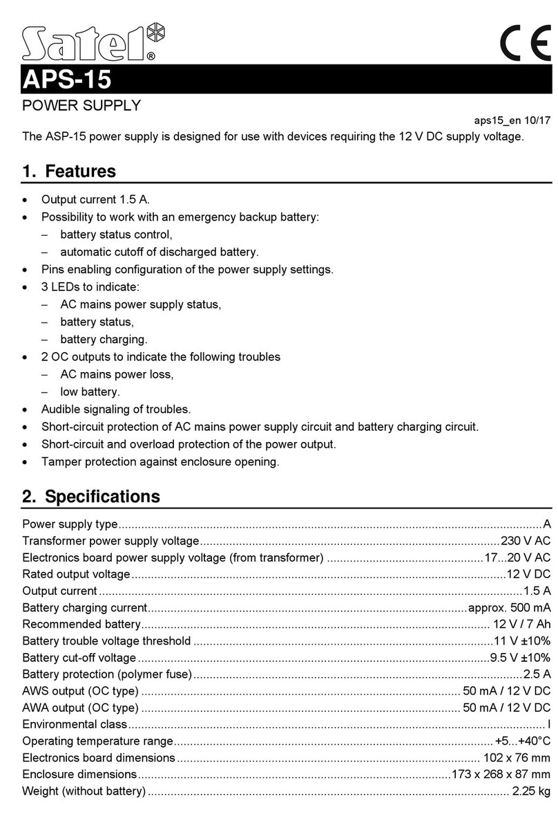
The APS-412 switching power supply is designed for powering 12 VDC devices. It is
provided with a connector for integration with SATEL devices.
If the power supply is to be used in conjunction with the devices specified below, make
sure their firmware version is at least:
INT-ADR –v. 2.02,
INT-E –v. 5.01,
INT-IORS –v. 2.01,
INT-O –v. 2.01,
INT-ORS –v. 2.01,
INT-PP –v. 2.01.
The APS-412 power supply meets the requirements of EN50131 Grade 2.
1. Features
Nominal output voltage (according to IEC 38): 12 VDC.
Output voltage stabilization.
Battery status supervision and low battery disconnect system.
Ability to work without a battery connected.
Output current:
–operation with battery: 3.5 A / 3 A,
–operation without battery: 4 A.
Battery charging current: 0.5 A / 1 A (selectable).
Connector for integration with SATEL devices.
Set of DIP-switches for configuration of the power supply settings.
3 LEDs to indicate:
–power output status,
–battery status,
–AC power status.
3 OC outputs to indicate the following troubles:
AC power loss,
low battery,
power supply overload.
Audible signaling of troubles.
Short-circuit protection of AC mains power supply circuit and battery charging circuit.
Short-circuit and overload protection of the power output.
Input interference filter.
Suitable for mounting in OPU-3 P and OPU-4 P / PW enclosures, as well as in distribution
switchboards on 35 mm DIN rail.

SATEL APS-412 3
2. Description of the power supply
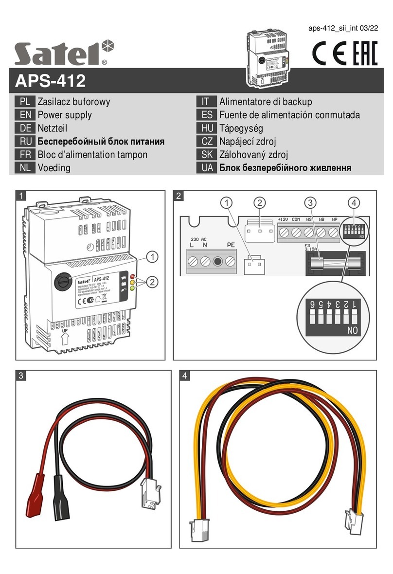
Explanations for Fig. 1:
F1 fuse (T 3.15 A) –AC circuit protection.
LEDs indicating status of the power supply:
–red LED –power output status:
OFF –OK (current consumption below 4 A),
flashing –overload (current consumption above 4 A).
–yellow LED –battery status:
ON –battery OK (or the battery testing mode disabled),
flashing –low battery (battery voltage below 11.5 V),
OFF –no battery or blown F3 fuse.
–green LED –AC power status:
ON –AC power OK,
flashing –no AC power or blown F1 fuse.
2.1 Electronics board
Description of terminals:
L –terminal for connecting phase conductor.
N –terminal for connecting neutral conductor.
PE –terminal for connecting protective conductor.
+12V –+12 VDC power output.
COM –common ground.
WS –OC type output signaling 230 VAC power loss.

4 APS-412 SATEL
WB –OC type output signaling low battery voltage (below 11.5 V).
WP –OC type output signaling power output overload (current consumption above 4 A).
In normal status, the OC type outputs are shorted to common ground (0 V). When trouble is
detected, the output is disconnected from common ground.
Figure 2 shows the part of the electronics board visible after the cover is removed.
battery connector. The wires are included in the set (Fig. 3).
connector for integration with SATEL devices. It is used to power SATEL devices and
transmit information on the power supply status. The SATEL device must have the same
connector. The connecting cable is included in the set (Fig. 4).
F3 fuse (T 3.15 A) –protection of battery charging circuit.
DIP-switches. Used for configuring the power supply (see: “Configuration”).
3. Configuration
The switch 6 must be set in OFF position.
Use the switches 1-5 to configure the power supply settings:
Switch 1 –audible trouble signaling: ON=enabled / OFF=disabled.
Switch 2 –battery test: ON=enabled / OFF=disabled.
Switch 3 –battery charging current: ON=1 A / OFF=0.5 A.
The battery charging current must not exceed 10% of the battery capacity.

SATEL APS-412 5
Switches 4 and 5 –AC power failure reporting delay: see table 1.
AC power failure reporting delay
Switch
3 s
60 s
600 s
1800 s
4
OFF
ON
OFF
ON
5
OFF
OFF
ON
ON
Table 1.
If the power supply is connected to the dedicated expander connector and the
expander has been identified as an expander with power supply, the AC power failure
reporting delay set by means of the switches will be disregarded. The delay shall be
programmed for the expander.
4. Installation
Disconnect power before making any electrical connections.
The power supply should be permanently connected to the 230 VAC mains supply. Before
you make the cabling, familiarize yourself with the electrical installation of the facility. Select
a circuit which is always alive to supply the unit. The power circuit should be protected with
a proper safety device. Instruct the owner / user of the power supply how to disconnect the
unit from the mains (e.g. indicate the fuse protecting the power circuit).
For a backup power supply, use a 12 V sealed lead-acid battery or other 12 V battery with
similar charging characteristics. The battery capacity must be selected to match the current
consumption in the system. If the power supply is to meet the requirements of the EN 50131
standard for Grade 2, refer to the “Standard requirements for battery” section.
Do not use batteries other than the recommended ones.
Do not connect deeply discharged battery to the power supply (with voltage
across unloaded terminals below 11.5 V). The battery should be precharged with
a proper charger.
The used batteries must not be discarded, but should be disposed of in
accordance with the existing rules for environment protection.
Before proceeding to installation, estimate the current consumption by all devices which are
to be supplied from the APS-412 power supply unit. The sum of currents consumed by these
devices must not exceed:
operation with battery: 3,5 A (battery charging current: 0.5 A) / 3 A (battery charging
current: 1 A),
operation without battery: 4 A.
1. Remove the cover of power supply terminals (Fig. 5).
2. Configure the power supply using the DIP switches (see: “Configuration”).

6 APS-412 SATEL
3. If the connector for supplying power to SATEL devices is to be used, connect to it the
cable shown in Fig. 4 (Fig. 6).
4. If screw terminals are to be used for supplying power to devices, screw the wires to +12V
and COM terminals.
5. Connect the battery wires (Fig. 3) to the connector on the electronics board (Fig. 7).
6. You can connect the trouble signaling outputs with control panel zones, or you can
connect e.g. LEDs to these outputs.
7. Run the 230 VAC power cable through the cable gland (Fig. 8).
8. Screw the 230 VAC power wires to terminals: phase conductor to L terminal, neutral
conductor to N terminal, and protective conductor to PE terminal (Fig. 9).
9. Screw the element fastening the 230 VAC power cable (Fig. 10).
10.Replace the cover of power supply terminals (Fig. 11) and fasten it with a screw (Fig.12).
11.Connect the battery to the dedicated wires (battery positive to red wire, negative –
to black).
12.Turn on 230 VAC power. When the AC power is present, the power supply will signal it
with a single beep sound and the LED turning ON.
If the power output is shorted to common ground or the F3 fuse is defective, the power
supply will turn off.

SATEL APS-412 7

8 APS-412 SATEL
5. Standard requirements for battery
If the power supply is to be used in an alarm system which is to meet requirements of the
EN 50131 standard for Grade 2, the battery should provide 12 hours of system operation in
the event of mains power loss. Table 2 contains information on what current must be used for
charging batteries of different capacities so as to meet the requirements of EN 50131 for
Grade 2.
Battery capacity
Charging current
Power supply output current
Alarm system with remote notification
18 Ah
1 A or 0.5 A
3 A
12 Ah
1 A or 0.5 A
2 A
7 Ah
1 A or 0.5 A
1 A
Alarm system without remote notification
36 Ah
1 A or 0.5 A
3 A
24 Ah
1 A or 0.5 A
2 A
12 Ah
1 A or 0.5 A
1 A
Table 2.
6. Battery testing by the power supply
After starting the power supply, provided that the battery testing mode is enabled and
a sufficiently charged battery is connected, the LED should go on after about 10
seconds. The battery is checked every 4 minutes for ten to twenty seconds. Duration of a full
test of the battery charge status is up to 12 minutes. If the battery voltage drops below
11.5 V, the power supply will report a trouble on the WB output, and the LED will start
blinking (optionally, the trouble may be audibly signaled). When the voltage goes down to
10.5 V, the power supply will disconnect the battery to protect it against full discharge and
damage. The LED will go off.
7. Specifications
Power supply type (according to EN 50131)........................................................................... A
Supply voltage .............................................................................................................230 VAC

SATEL APS-412 9
Efficiency ...................................................................................................................up to 88%
Nominal output voltage (according to IEC 38) ...............................................................12 VDC
Actual output voltage ..................................................................................................13.8 VDC
Output current
operation with battery connected..................................................................................4 A
operation without battery connected................................................................. 3.5 A / 3 A
Battery charging current (selectable)........................................................................ 0.5 A / 1 A
Current consumption of power supply circuits .................................................................57 mA
Battery failure voltage threshold ............................................................................11.5 V ±10%
Battery cut-off voltage............................................................................................10.5 V ±10%
OC type outputs (WS, WB, WP) ......................................................................50 mA / 12 VDC
Security grade according to EN 50131 .........................................................................Grade 2
Environmental class.................................................................................................................II
Operating temperature range...................................................................................-10...+55°C
Enclosure dimensions....................................................................................77 x 122 x 59 mm
Weight...............................................................................................................................306 g
Other manuals for APS-412
2
Table of contents
Other Satel Power Supply manuals

Satel
Satel APS-30 User manual

Satel
Satel APS-1412 User manual

Satel
Satel APS-612 User manual

Satel
Satel APS-612 User manual

Satel
Satel APS-30 User manual

Satel
Satel APS-1012 User manual

Satel
Satel APS-524 User manual

Satel
Satel APS-612 User manual

Satel
Satel APS-412 User manual

Satel
Satel APS30BO User manual
Popular Power Supply manuals by other brands

Delta Elektronika
Delta Elektronika SM15K Series product manual

Rohde & Schwarz
Rohde & Schwarz R&S NGP822 user manual

Whelen Engineering Company
Whelen Engineering Company ISP4HS installation guide

BGS technic
BGS technic 3383 Safety and operating instructions

Allied Telesis
Allied Telesis IE048-480 installation guide

SOMFY
SOMFY 9018245 installation guide