TEXIO DCS-7500A Series Owner's manual

PROGRAMMING MANUAL
DIGITAL STORAGE OSCILLOSCOPE
DCS-7500A SERIES
DCS-7507A DCS-7510A DCS-7515A
B71-0048-01

■ About a trademark, a registered trademark
A company name and the brand name mentioned in this instruction
manual are the trademark or the registered trademark of each
company or group in each country and region.
■ About this instruction manual
When copying the part or all of contents of this instruction manual, seek
the copyright holder.
In addition, the specifications of the product and the contents of this
instruction manual are subject to change without notice for
improvement. Please check to our website for the latest version.

CONTENTS
1. INTERFACE OVERVIEW........................ 1
1-1. Rear Panel Overview........................................ 1
1-2. Configuring the USB Interface........................... 1
2. COMMAND OVERVIEW ......................... 3
2-1. Command Syntax ............................................. 3
3. COMMAND DETAILS............................. 4
3-1. System Command ............................................ 5
3-1-1. *IDN..........................................................................................5
3-1-2. *LRN.........................................................................................6
3-1-3. *RST.........................................................................................6
3-1-4. :SYSTem:ERRor.......................................................................7
3-1-5. SYSTem:VERSion....................................................................7
3-2. Acquisition Command ....................................... 8
3-2-1. :ACQuire:AVERage ..................................................................8
3-2-2. :ACQuire:HDELay.....................................................................9
3-2-3. :ACQuire:MODe........................................................................9
3-2-4. :ACQuire<X>:LMEMory ..........................................................10
3-2-5. :ACQuire<X>:MEMory ............................................................12
3-3. Autoset Command.......................................... 13
3-3-1. :AUToset.................................................................................13
3-4. Channel / Math Command .............................. 14
3-4-1. :CHANnel<X>:BWLimit...........................................................14
3-4-2. :CHANnel<X>:COUPling ........................................................15
3-4-3. :CHANnel<X>:DISPlay ...........................................................15
3-4-4. :CHANnel<X>:EXPand ...........................................................16
3-4-5. :CHANnel<X>:INVert..............................................................16
3-4-6. :CHANnel<X>:MATH ..............................................................17
3-4-7. :CHANnel<X>:OFFSet............................................................18
3-4-8. :CHANnel<X>:PROBe:RATio .................................................19
3-4-9. :CHANnel<X>:PROBe:TYPE..................................................19
3-4-10. :CHANnel<X>:SCALe...........................................................20
3-5. Math Command.............................................. 21
3-5-1. :MATH:OPERator ...................................................................21
3-5-2. :MATH:POSition......................................................................22
3-5-3. :MATH:FFT:SOURce..............................................................22
3-5-4. :MATH:FFT:WINDow..............................................................23
3-5-5. :MATH:FFT:SCALe.................................................................23
3-5-6. :MATH:FFT:HORizontal:SCALe..............................................24
3-5-7. :MATH:FFT:HORizontal:POSition...........................................24

3-6. Cursor Command ........................................... 25
3-6-1. :CURSor:X<X>Position...........................................................25
3-6-2. :CURSor:Y<X>Position...........................................................26
3-6-3. :CURSor:<X>DELta................................................................27
3-6-4. :CURSor:<X>DISplay .............................................................28
3-6-5. :CURSor:SOURce ..................................................................28
3-7. Display Command .......................................... 29
3-7-1. :DISPlay:ACCumulate.............................................................29
3-7-2. :DISPlay:CONTrast.................................................................30
3-7-3. :DISPlay:GRATicule................................................................30
3-7-4. :DISPlay:WAVeform................................................................31
3-7-5. :REFResh ...............................................................................31
3-8. Measure Command ........................................ 32
3-8-1. :MEASure:DELAY1.................................................................33
3-8-2. :MEASure:DELAY2.................................................................33
3-8-3. :MEASure:FALL......................................................................34
3-8-4. :MEASure:FFFDelay...............................................................34
3-8-5. :MEASure:FFRDelay ..............................................................35
3-8-6. :MEASure:FOVShoot..............................................................35
3-8-7. :MEASure:FPReshoot.............................................................36
3-8-8. :MEASure:FREQuency...........................................................36
3-8-9. :MEASure:FRFDelay ..............................................................37
3-8-10. :MEASure:FRRDelay............................................................37
3-8-11. :MEASure:LFFDelay.............................................................38
3-8-12. :MEASure:LFRDelay.............................................................38
3-8-13. :MEASure:LRFDelay.............................................................39
3-8-14. :MEASure:LRRDelay ............................................................39
3-8-15. :MEASure:NWIDth................................................................40
3-8-16. :MEASure:PDUTy.................................................................40
3-8-17. :MEASure:PERiod ................................................................41
3-8-18. :MEASure:PWIDth................................................................41
3-8-19. :MEASure:RISe.....................................................................42
3-8-20. :MEASure:ROVShoot ...........................................................42
3-8-21. :MEASure:RPReshoot ..........................................................43
3-8-22. :MEASure:SOURce ..............................................................43
3-8-23. :MEASure:VAMPlitude..........................................................44
3-8-24. :MEASure:VAVerage ............................................................44
3-8-25. :MEASure:VHI.......................................................................45
3-8-26. :MEASure:VLO .....................................................................45
3-8-27. :MEASure:VMAX ..................................................................46
3-8-28. :MEASure:VMIN....................................................................46
3-8-29. :MEASure:VPP .....................................................................47
3-8-30. :MEASure:VRMS..................................................................47
3-9. Go No-Go Command ...................................... 48
3-9-1. :GONogo:CLEar......................................................................48
3-9-2. :GONogo:EXECute.................................................................49
3-9-3. :GONogo:FUNCtion................................................................49

3-9-4. :GONogo:NGCount?...............................................................50
3-9-5. :GONogo:NGDefine................................................................50
3-9-6. :GONogo:SOURce..................................................................51
3-9-7. :GONogo:VIOLation................................................................51
3-9-8. :TEMPlate:MODe....................................................................52
3-9-9. :TEMPlate:MAX ......................................................................53
3-9-10. :TEMPlate:MIN......................................................................54
3-9-11. :TEMPlate:POSition:MAX .....................................................55
3-9-12. :TEMPlate:POSition:MIN ......................................................56
3-9-13. :TEMPlate:SAVe:MAXimum..................................................57
3-9-14. :TEMPlate:SAVe:MINimum...................................................57
3-9-15. :TEMPlate:TOLerance ..........................................................58
3-9-16. :TEMPlate:SAVe:AUTo.........................................................59
3-10. Data Logging Command ............................... 60
3-10-1. :DATALOG:STATE ...............................................................60
3-10-2. :DATALOG:SOURce.............................................................60
3-10-3. :DATALOG:SAVe..................................................................61
3-10-4. :DATALOG:INTerval .............................................................61
3-10-5. :DATALOG:DURation ...........................................................62
3-11. Save/Recall Command.................................. 63
3-11-1. :MEMory<X>:RECall:SETup.................................................63
3-11-2. :MEMory<X>:RECall:WAVeform...........................................64
3-11-3. :MEMory<X>:SAVe:SETup...................................................64
3-11-4. :MEMory<X>:SAVe:WAVeform.............................................65
3-11-5. *RCL.....................................................................................65
3-11-6. :REF<X>:DISPlay.................................................................66
3-11-7. :REF<X>:LOCate..................................................................66
3-11-8. :REF<X>:SAVe.....................................................................67
3-11-9. *SAV.....................................................................................67
3-12. Time (Horizontal) Command.......................... 68
3-12-1. :TIMebase:DELay.................................................................68
3-12-2. :TIMebase:SCALe.................................................................69
3-12-3. :TIMebase:SWEep................................................................70
3-12-4. :TIMebase:WINDow:DELay..................................................70
3-12-5. :TIMebase:WINDow:SCALe..................................................71
3-13. Trigger Command......................................... 72
3-13-1. :FORCe.................................................................................72
3-13-2. :RUN.....................................................................................72
3-13-3. :SINGle .................................................................................73
3-13-4. :STOP...................................................................................73
3-13-5. *TRG.....................................................................................73
3-13-6. :TRIGger:COUPle.................................................................74
3-13-7. :TRIGger:FREQuency...........................................................74
3-13-8. :TRIGger:HOLDoff................................................................75
3-13-9. :TRIGger:LEVel.....................................................................75
3-13-10. :TRIGger:MODe..................................................................76
3-13-11. :TRIGger:NREJ...................................................................76

3-13-12. :TRIGger:PULSe:MODe .....................................................77
3-13-13. :TRIGger:PULSe:TIMe........................................................78
3-13-14. :TRIGger:REJect.................................................................78
3-13-15. :TRIGger:SLOPe.................................................................79
3-13-16. :TRIGger:STATe.................................................................80
3-13-17. :TRIGger:SOURce..............................................................81
3-13-18. :TRIGger:TYPe ...................................................................81
3-13-19. :TRIGger:VIDeo:FIELd........................................................82
3-13-20. :TRIGger:VIDeo:LINe..........................................................83
3-13-21. :TRIGger:VIDeo:POLarity ...................................................84
3-13-22. :TRIGger:VIDeo:TYPe........................................................84
1
1.INTERFACE OVERVIEW
This manual describes how to use the DCS-7500A series’ remote
command functionality and lists the command details. The Overview
chapter describes how to configure the DCS-7500A series USB remote
control interface.
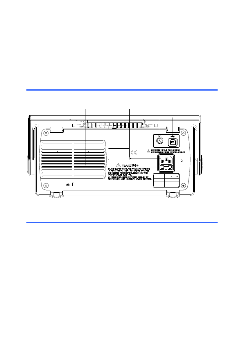
1-1.Rear Panel Overview
LINE VOLTAGE AC 100 240V
FUSE RATING
RANGE
T1A 250V
FREQUENCY 50 60Hz
POWER MAX. 18W 40VA
USB portCAL outputPower cord socketFuse socket
1-2.Configuring the USB Interface
USB connection
PC side
connector
Type A, host
DCS-7500A
side connector
Type B, device
Speed
1.1/2.0 (full speed)

2
USB driver
software
OS
Microsoft Windows 7 or higher
File name
TEXIO_CDC.inf (Attached CD)
DCS-7500A is allocated to the COM port when
installing it. The set is recognized as a serial
communications equipment on PC. You must have
administrator account to install.
Serial port setting:
Speed 12Mbps or less
Data-bits
: 8 bit
Parity
: none
Stop-bit
: 1 bit
Flow-control
: none
Panel operation
1. Connect the USB cable to the
USB device port on the rear.
2. When the PC asks for the USB driver or
‘Unknown device’ listed in Device Manager,
install TEXIO_CDC.inf attached CD.
3. On the PC, activate a terminal application such
as PuTTY. To check the COM port No., see the
Device Manager in the PC.
4. Run this query command via the terminal
application.
*idn?
This command should return the manufacturer,
model number, serial number, and firmware
version in the following format.
TEXIO, DCS-75XXA, XXXXXXX, V1.00
5. Configuring the command interface is completed.
Refer to the other chapters for more details.
CAUTION:
If there is no response, please confirm a device
driver, COM port number or the connection of the
cable and so on.
CAUTION:
If you change the setting of the USB port in the
connection with the PC, May not be able to
communicate. Please restart your PC in this case.
3
2.COMMAND OVERVIEW
The command syntax section shows you the basic syntax rules you have
to apply when using commands.
2-1.Command Syntax
Compatible
standard
USB CDC_ACM compatible
SCPI, 1994 (partially compatible)
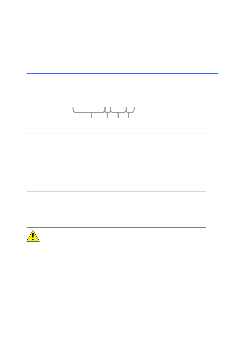
Command
format
trig:del:mod <NR1>LF
1 2 3 4
1: command header
2: single space
3: parameter
4: message terminator
Parameter
Type
Description
Example
<Boolean>
boolean logic
0, 1
<NR1>
Integers
0, 1, 2, 3
<NR2>
decimal numbers
0.1, 3.14, 8.5
<NR3>
floating point
4.5e-1, 8.25e+1
<NRf>
any of NR1, 2, 3
1, 1.5, 4.5e-1
Message
terminator
LF^END
line feed code (hexadecimal 0A)
with END message
LF
line feed code
<dab>^END
last data byte with END message
CAUTION:
Commands are non-case sensitive.
On the real input of the value to the parameter,
please do not use the symbol as “<”, “>”, “|”.
The above symbols are used to facilitate
distinction with this manual.

4
3.COMMAND DETAILS
3-1. System Command ............................................ 5
3-2. Acquisition Command ....................................... 8
3-3. Autoset Command.......................................... 13
3-4. Channel / Math Command .............................. 14
3-5. Math Command.............................................. 21
3-6. Cursor Command ........................................... 25
3-7. Display Command .......................................... 29
3-8. Measure Command ........................................ 32
3-9. Go No-Go Command ...................................... 48
3-10. Data Logging Command ............................... 60
3-11. Save/Recall Command.................................. 63
3-12. Time (Horizontal) Command.......................... 68
3-13. Trigger Command......................................... 72

5
3-1.System Command
3-1-1. *IDN..........................................................................................5
3-1-2. *LRN.........................................................................................6
3-1-3. *RST.........................................................................................6
3-1-4. :SYSTem:ERRor.......................................................................7
3-1-5. :SYSTem:VERSion...................................................................7
3-1-1.*IDN
Query
Description
Returns the oscilloscope ID: manufacturer, model
name, serial number, and firmware version.
Same as: Utility key → F4
Syntax
*idn?
Example
*idn?
TEXIO, DCS-7515A, XXXXXXX, V1.00
Returns
the ID
A kind of Query or Set is
shown.
Query
: Query
Set
: Set

6
3-1-2.*LRN
Query
Description
Returns the oscilloscope settings as a data string.
Syntax
*lrn?
Example
*lrn?
:DISPlay:WAVeform 0;ACCumulate 0;CONTrast 0;GRATicule
0;:CHANnel1:DISPlay 1;BWLimit 0;COUPling 0;INVert
0;OFFSet 2.000e+00;PROBe 3;SCALe
2.000e+00;:CHANnel2:DISPlay 1;BWLimit 0;COUPling 0;INVert
0;OFFSet 2.000e+00;PROBe 3;SCALe
2.000e+00;:CHANnel1:MATH 0;:TIMebase:SWEep 0;SCALe
2.500e-06;DELay 0.000e+00;WINDow:SCALe
2.50000e-07;DELay 0.00000e+00;:ACQuire:MODe 0;AVERage
0;:TRIGger:TYPe 0;SOURce 0;MODe 1;SLOP 0;COUPle
1;REJect 0;NREJ 0;LEVel 0.00000e+00;PULSe:MODe: 0;TIMe
0.00000e+00;:VIDeo:TYPe 1;POLarity 0;FIELd 0;LINe
0;:CURSor:SOURce 1;XDISPlay 0;X1Position 75;X2Position
175;YDISPlay 0;Y1Position 54;Y2Position 154;:REF1:DISPlay
0;LOCate 50;:REF2:DISPlay 0;LOCate -50;:RUN
3-1-3.*RST
Set
Description
Resets the DCS-7500A (recalls the default panel
settings).
Same as: Save/Recall key → F1
Syntax
*rst
CAUTION:
In the help mode (the screen display of the function
explanation), the command is invalid.
CAUTION:
The saved content in the internal memory is not
initialized by the recall function of “Default Setup”.

7
3-1-4.:SYSTem:ERRor
Query
Description
Returns the oscilloscope system error message, if
there is any.
Syntax
< Long >
< Short >
:system:error?
:syst:err?
Parameter
ID
Contents
ID
Contents
-100
command error
-102
syntax error
-220
parameter error
-221
settings conflict
-222
data out of range
-223
too much data
-224
illegal parameter
-232
invalid format
Example
:system:error?
-102
Indicates that the command
syntax is wrong.
:
3-1-5.SYSTem:VERSion
Query
Description
Returns the SCPI version to which the oscilloscope
complies to. This is returned as the SCPI version
year and revision number (YYYY.V).
Syntax
< Long >
< Short >
:system:version?
:syst:vers?
Example
:syst:vers?
1992.0
Returns the SCPI version
as 1992.0
8
3-2.Acquisition Command
3-2-1. :ACQuire:AVERage ..................................................................8
3-2-2. :ACQuire:HDELay.....................................................................9
3-2-3. :ACQuire:MODe........................................................................9
3-2-4. :ACQuire<X>:LMEMory ..........................................................10
3-2-5. :ACQuire<X>:MEMory ............................................................12
3-2-1.:ACQuire:AVERage
Set
Query
Description
Selects or returns the average number of waveform
acquisition in the average acquisition mode.
Same as: Acquire key → F2
Syntax
< Long >
< Short >
:acquire:average <NR1>
:acquire:average?
:acq:aver <NR1>
:acq:aver?
Parameter
<NR1>
Average
No.
<NR1>
Average
No.
1
2
5
32
2
4
6
64
3
8
7
128
4
16
8
256
CAUTION:
Before using this command, select the average
acquisition mode. See the example below.
Example
:acquire:mode 2
:acquire:average 2
Selects the average
acquisition mode,
and select the average
number 4.

9
3-2-2.:ACQuire:HDELay
Set
Query
Description
Set or query Delay On or Delay Off.
Same as: Acquire key → F4
Syntax
< Long >
< Short >
:acquire:hdelay <Boolean>
:acquire:hdelay?
:acq:hdel <Boolean>
:acq:hdel?
Parameter
<NR1>
Delay
0
Off
1
On
Example
:acquire:hdelay 1
:acquire:hdelay?
1
Turns Delay On.
Returns the Delay as On.
3-2-3.:ACQuire:MODe
Set
Query
Description
Selects or returns the acquisition mode.
Same as: Acquire key → F1 ~ F3
Syntax
< Long >
< Short >
:acquire:mode <NR1>
:acquire:mode?
:acq:mod <NR1>
:acq:mod?
Parameter
<NR1>
Mode
<NR1>
Mode
0
Normal
2
Average
1
Peak detect
Example
:acquire:mode 2
:acquire:average 2
Selects the average
acquisition mode,
and select the average
number 4.

10
3-2-4.:ACQuire<X>:LMEMory
Query
Description
Returns the total waveform data in the acquisition
memory for long memory.
Syntax
< Long >
< Short >
:acquire<X>:lmemory?
:acq<X>:lmem?
Parameter
<X>
Channel
1/2
Channel1/2
CAUTION:
Please note that the number of points is limited to
4000 when the scope is running.
You can get the full memory depth when the
“Single” key is pressed with a triggered signal.
You can also get the full memory depth when the
“STOP” key is pressed,
However, the long memory may not fully fill up if a
slow time base is used with a fast sample rate
Also note that there are several time base settings
that don’t result in 100% of available memory, due
to a limited number of available sample rates.
Example
:acquire1:lmemory?
Returns the channel 1
long memory waveform
data
If both channels are
active up to 1M points
are returned. If only CH1
is active then up to 2M
points are returned.
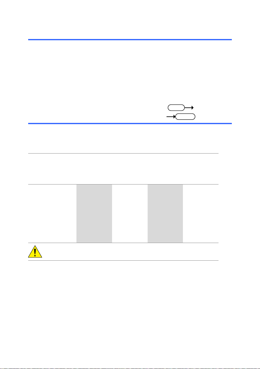
Data format
Six data elements are concatenated to form one
data string.
#
A
B
C
D
E
F
A: Data size digit
B: Data size
C: Time interval
D: Channel indicator
E: Reserved data
F: Waveform data

11
# (1 byte)
The start of data transfer. The value is 0X23
(“#” in ASCII code).
Data size digit (1 byte)
Indicates the number of digits used for the data
string that follows. The data size digit is 4 for 4000
points, 7 for 1M or 2M points.
Data size (4 or 7 bytes)
Indicates the data size. The data size varies from
8008 (4000 points), 2000008 (1M points) or
4000008 (2M points).
8 bytes are total of Time interval, Channel indicator,
and Reserved data.
Time interval (4 bytes)
Indicates the time interval between two adjacent
sampling points in the floating point format,
compatible with IEEE 754 standards.
Note: The data is sorted in the little-endian format.
Channel indicator (1 byte)
Indicates the channel, 1 (0X01) or 2 (0X02).
Reserved data (3 bytes)
An unused data block, 3 bytes.
Waveform data
(8000, 2000000 or 4000000 bytes)
The waveform data comprised of 2M data points.
Each point is made up of 2 bytes (16 bits), two's
complement, high byte (MSB) first.
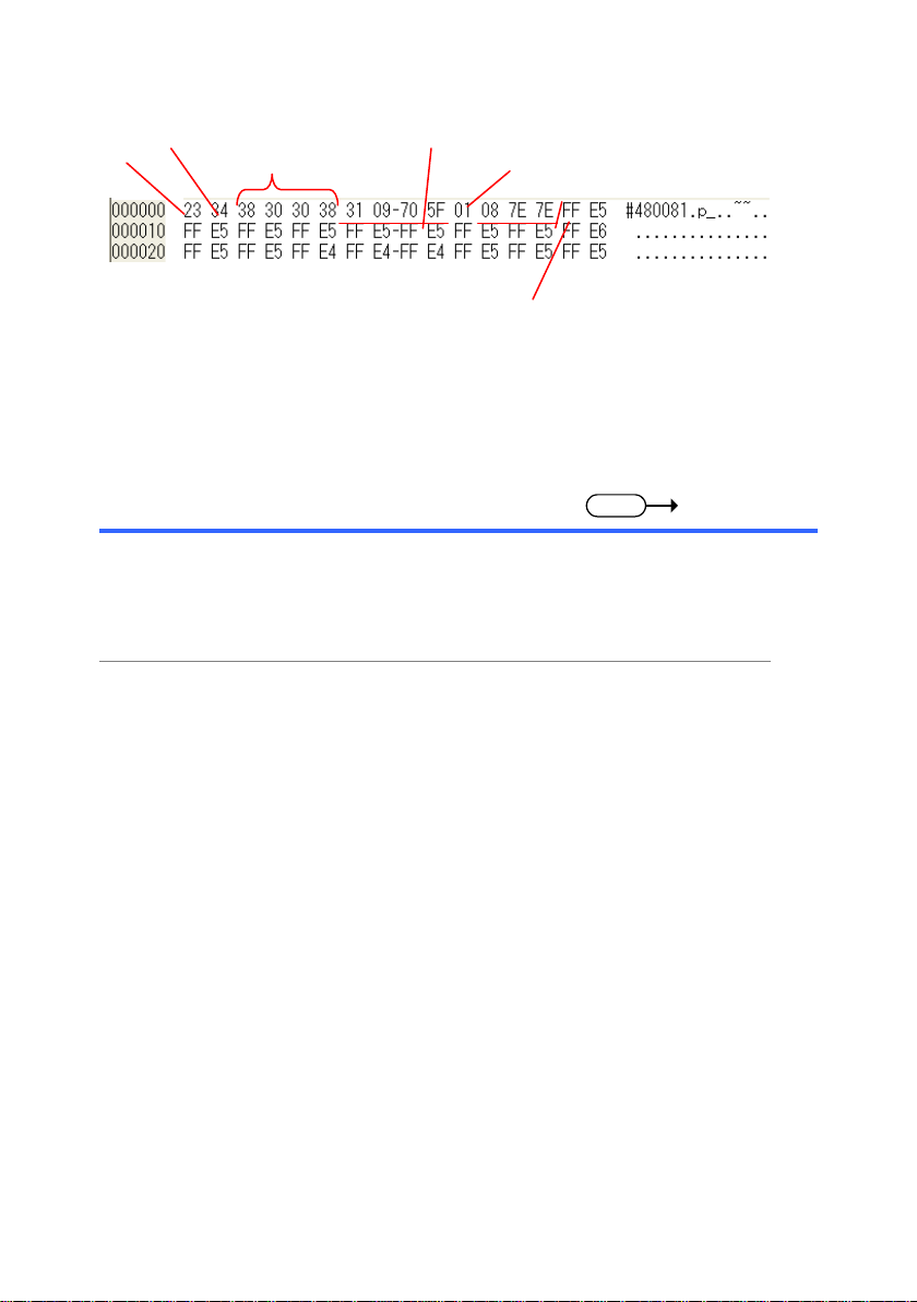
Example 1M points data
Data size digit(7) Time interval(0X31 09 70 5F)
# Data size(2000008) Channel indicator(0X01)
Reserved data
Waveform data after this(FF)
Reserved data

12
3-2-5.:ACQuire<X>:MEMory
Query
Description
Returns the total waveform data in the acquisition
memory.
Syntax
< Long >
< Short >
:acquire<X>:memory?
:acq<X>:mem?
Parameter
<X>
Channel
1/2
Channel1/2
Example
:acquire1:memory?
Returns the channel 1
waveform data.
Data format
Six data elements are concatenated to form one
data string.
#
A
B
C
D
E
F
A: Data size digit
B: Data size
C: Time interval
D: Channel indicator
E: Reserved data
F: Waveform data
# (1 byte)
The start of data transfer. The value is 0X23
(“#” in ASCII code).
Data size digit (1 bytes)
Indicates the number of digits used for the data
string that follows. The data size digit is always 4.
Data size (4 bytes)
Indicates the data size. The data size is always
8008 (4000 points per channel).
8 bytes are total of Time interval, Channel indicator,
and Reserved data.
Time interval (4 bytes)
Indicates the time interval between two adjacent
sampling points in the floating point format,
compatible with IEEE 754 standards.
Note: The data is sorted in the little-endian format.
Channel indicator (1 byte)
Indicates the channel, 1 (0X01) or 2 (0X02).
Reserved data (3 bytes)
An unused data block, 3 bytes.
Waveform data (8000 bytes)
The waveform data comprised of 4000 data points.
Each point is made up of 2 bytes (16 bits), two's
complement, high byte (MSB) first.
13
Example
Data size digit(4) Time interval(0X31 09 70 5F)
# Data size(8008) Channel indicator(0X01)
Reserved data
Waveform data after this(FF)
3-3.Autoset Command
3-3-1.:AUToset
Set
Description
Runs the Autoset function to automatically
configure the horizontal scale, vertical scale, and
trigger according to the input signal.
Same as: Auto Set key
Syntax
< Long >
< Short >
:autoset
:aut

14
3-4.Channel / Math Command
3-4-1. :CHANnel<X>:BWLimit...........................................................14
3-4-2. :CHANnel<X>:COUPling ........................................................15
3-4-3. :CHANnel<X>:DISPlay ...........................................................15
3-4-4. :CHANnel<X>:EXPand ...........................................................16
3-4-5. :CHANnel<X>:INVert..............................................................16
3-4-6. :CHANnel<X>:MATH ..............................................................17
3-4-7. :CHANnel<X>:OFFSet............................................................18
3-4-8. :CHANnel<X>:PROBe:RATio .................................................19
3-4-9. :CHANnel<X>:PROBe:TYPE..................................................19
3-4-10. :CHANnel<X>:SCALe...........................................................20
3-4-1.:CHANnel<X>:BWLimit
Set
Query
Description
Selects or returns the bandwidth limit on/off.
Same as: Channel key → F3
Syntax
< Long >
< Short >
:channel<X>:bwlimit
<Boolean>
:channel<X>:bwlimit?
:chan<X>:bwl
<Boolean>
:chan:bwl?
Parameter
<X>
Channel
<NR1>
Limit
1/2
CH1/2
0
Off
1
On
Example
:channel1:bwlimit 1
Turns on the bandwidth
limit for Channel 1.
This manual suits for next models
3
Table of contents
Other TEXIO Test Equipment manuals


