TEXIO DCS-2000E SERIES Owner's manual

PROGRAMMING MANUAL
DIGITAL STORAGE OSCILLOSCOPE
DCS-2000E SERIES
B71-0461-01

■About a trademark, a registered trademark
A company name and the brand name mentioned in this
instruction manual are the trademark or the registered trademark
of each company or group in each country and region.
■About this instruction manual
When copying the part or all of contents of this instruction manual,
seek the copyright holder.
In addition, the specifications of the product and the contents of
this instruction manual are subject to change without notice for
improvement. Please check to our website for the latest version.

Contents
USING THE PRODUCT SAFELY.............................................................Ⅰ-Ⅴ
1. INTERFACE OVERVIEW ................................................. 1
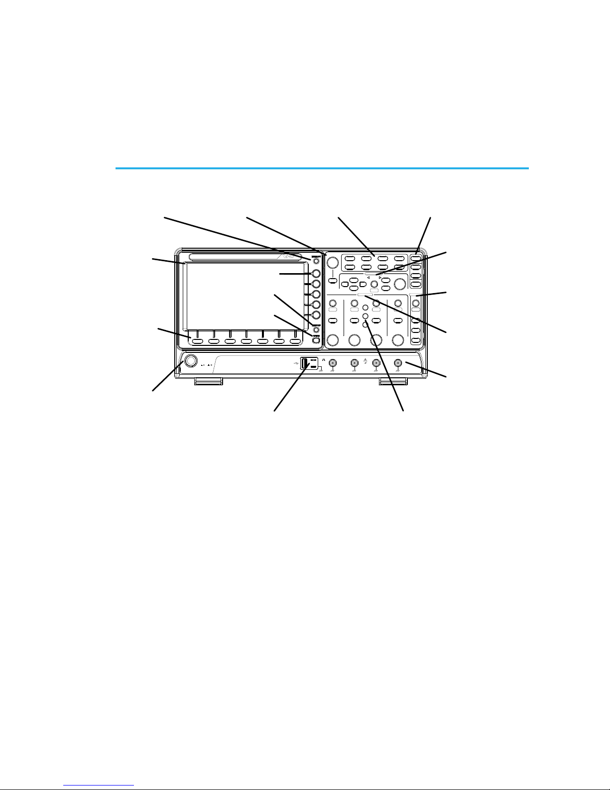
1-1. Front Panel Overview ........................................................ 1
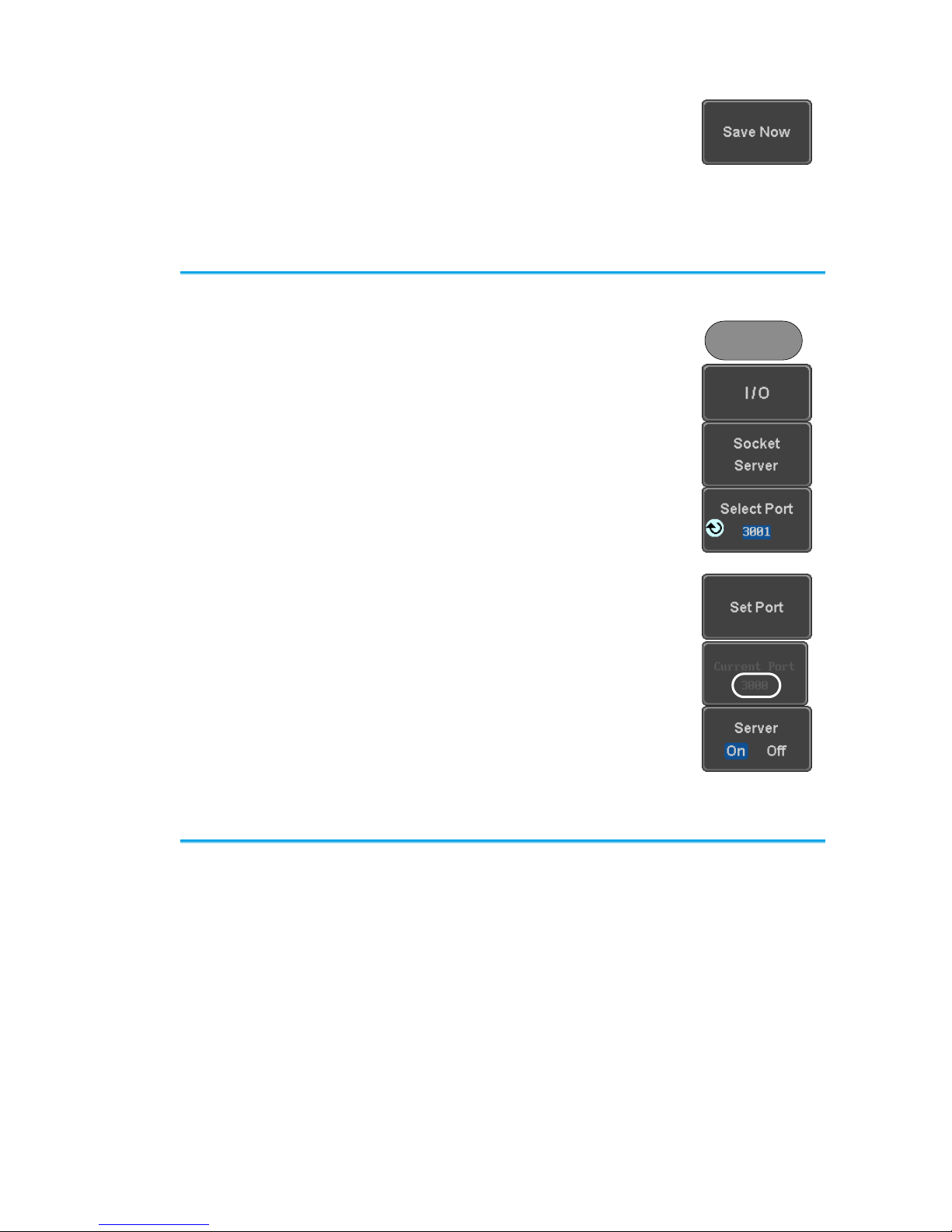
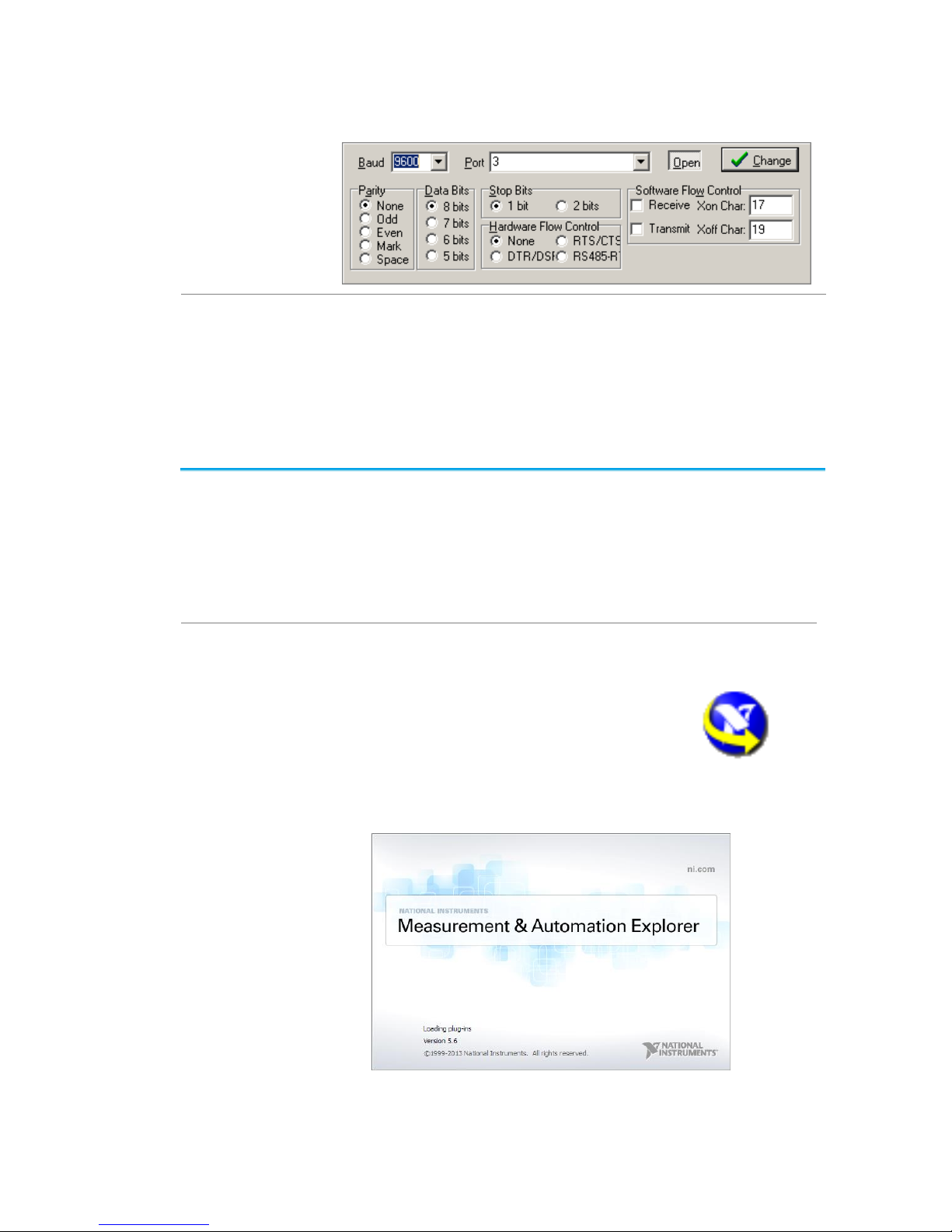
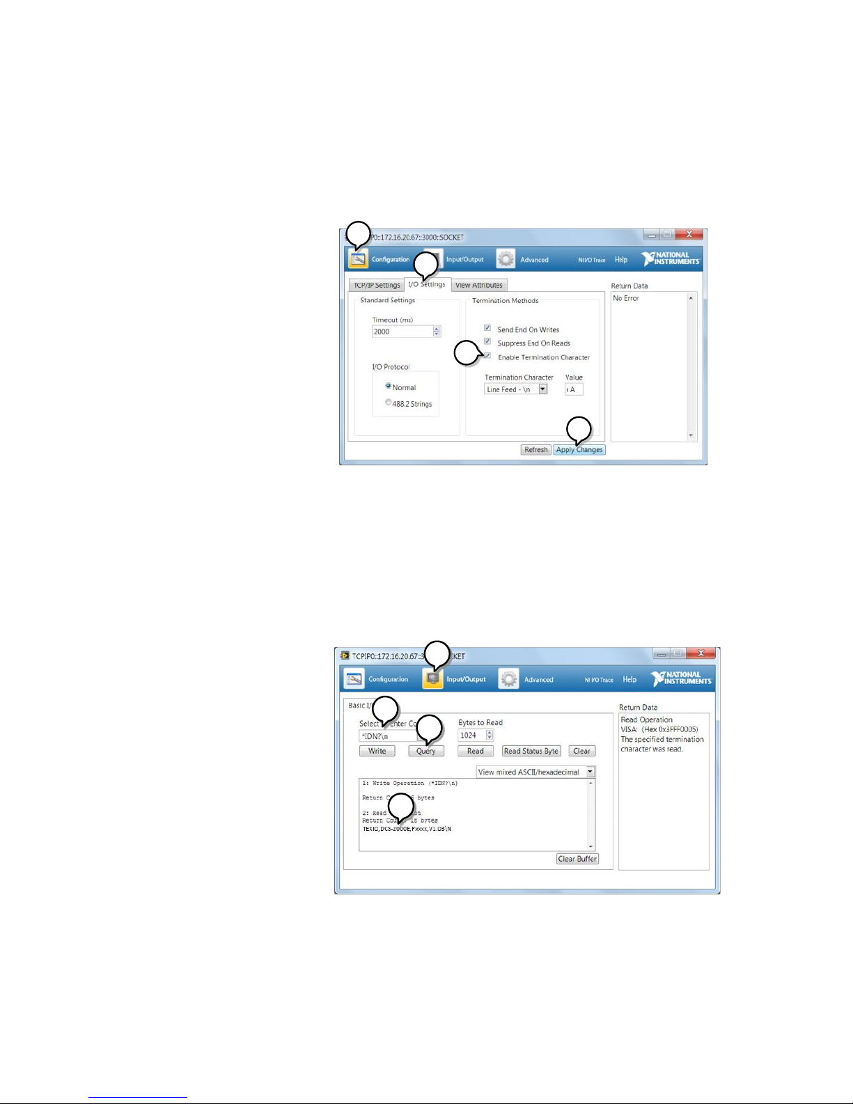
1-2. Interface Configuration ...................................................... 2
2. COMMAND OVERVIEW .................................................. 9
2-1. Command Syntax .............................................................. 9
3. COMMAND DETAILS..................................................... 10
3-1. Common Commands.........................................................11
3-2. Acquisition Commands......................................................16
3-3. Autoscale Commands .......................................................21
3-4. Vertical Commands...........................................................22
3-5. Math Commands...............................................................26
3-6. Cursor Commands ............................................................33
3-7. Display Commands ...........................................................41
3-8. Hardcopy Commands........................................................44
3-9. Measure Commands .........................................................47
3-10. Measurement Commands ................................................68
3-11. Reference Commands.....................................................73
3-12. Run Command................................................................75
3-13. Timebase Commands......................................................76
3-14. Trigger Commands .........................................................78
3-15. System Commands .......................................................109
3-16. Save/Recall Commands ................................................110
3-17. Ethernet Commands .....................................................113
3-18. Time Commands...........................................................113
3-19. Bus Decode Commands ................................................114
3-20. Mark Commands...........................................................126
3-21. Search Commands........................................................127
3-22. Label Commands ..........................................................154
3-23. Segment Commands .....................................................158
3-24. DVM Commands ...........................................................164
3-25. Go_NoGo Commands ...................................................166
3-26. Data Logging Commands ..............................................171
3-27. Remote DiskCommands ................................................173
4. APPENDX ....................................................................175
4-1. Error messages ..............................................................175

1
1. INTERFACE OVERVIEW
This manual describes how to use the remote command functionality and
lists the command details. The Overview chapter describes how to
configure the USB remote control interface and Ethernet interface.
1-1. Front Panel Overview
VARIABLE
POSITION
HORIZONTAL
POSITION
POSITION POSITION POSITION
VERTICAL
MATH
REF
BUS
TRIGGER
LEVEL
PUSH TO
ZERO
PUSH TO
ZERO PUSH TO
ZERO PUSH TO
ZERO PUSH TO
ZERO PUSH TO
ZERO
SCALE
POWER CH1 CH2 CH3 CH4
2V
1MW16pF
Digital Storage Oscilloscope
200 MHz 1 GS/s Visual Persistence Oscilloscope
LCD
Variable knob
and Select key Autoset, Run/Stop, Single
and Default settings
CH1~CH4
Trigger
controls
Function
keys
USB Host port, Probe
Compensation terminals
Power
button
Hardcopy key
Option key
Math, Reference
and Bus keys
Bottom
menu
keys
Horizontal
controls
Menu key
Vertical
controls
Side menu keys

2
1-2. Interface Configuration
1-2-1. Configure USB Interface
USB Configuration
PC side connector
Type A, host
DCS-2000E side
connector
Type B, device
Speed
1.1/2.0 (high speed)
USB Class
USB-CDC
OS
USB Driver
Windows7(32bit/64bit) or higher
TEXIO_CDC*.inf
Panel Operation
1. Press the Utility key.
Utility
2. Press I/O from the bottom menu.
3. Press USB Device Port from the side
menu and select Computer.
4. Connect the USB cable to the rear
panel device port.
5. When the PC asks for the USB driver or ‘Unknown
device’ listed in Device Manager, install TEXIO-
CDC*.inf attached CD.
6. If the computer can not recognize the new hardware
due to the security, please go to update the driver
from the "Other devices" in the Device Manager.
Note
You must have administrator account to install driver.
1-2-2. Configure the Ethernet Interface
Ethernet
Configuration
MAC Address
Domain Name
Instrument Name
DNS IP Address
User Password
Gateway IP Address
Instrument IPAddress
Subnet Mask
Background
The Ethernet interface is used for remote control using a
socket server connection.
Panel Operation
1. Connect the Ethernet cable to the LAN
port on the rear panel.
2. Press the Utility key.
Utility
3. Press I/O from the bottom menu.

3
4. Press Ethernet from the side menu.
5. Set DHCP/BOOTP to On or Off from
the side menu.
Note
IP addresses will automatically be assigned with
DHCP/BOOTP set to on. For Static IP Addresses,
DHCP/BOOTP should be set to off.
6. Use the Up and Down arrows on the
side menu to navigate to each Ethernet
configuration item.
Items
MAC Address, Instrument Name, User
Password, Instrument IPAddress,
Domain Name, DNS IPAddress,
Gateway IP Address, Subnet Mask
7. Use the Variable knob to highlight a
character and use the Select key to
choose a character.
VARIABLE
Select
Press Backspace to delete a
character.

4
Press Save Now to save the
configuration. Complete will be
displayed when successful.
1-2-3. Configure Socket Server
The DCS-2000E supports socket server functionality for direct and full
duplex communication with a client PC or device over LAN. By default, the
Socket Server is off.
Configure Socket
Server
1. Configure the IP address for the DCS-
2000E.
2. Press the Utility key.
Utility
3. Press I/O from the bottom menu.
4. Press Socket Server from the side
menu.
5. Press Select Port and choose the port
number with the Variable knob.
Range
1024~65535
6. Press Set Port to confirm the port
number.
7. The Current Port icon will update to the
new port number.
8. Press Server and turn the socket
server On.
1-2-4. USB Functionality Check
Terminal
Application (USB)
Invoke the terminal application such as PuTTY or
RealTerm. For USB, set the COM port, baud rate, stop
bit, data bit, and parity accordingly.
To check the COM port number and associated port
settings, see the Device Manager in the PC. For
Windows:
Control panel → Hardware and Sound→ Device
Manager

5
Example: Configuring RealTerm for RS-232C
communication.
Functionality
Check
Key in this query command via the terminal application.
*idn?
This should return the Manufacturer, Model number,
Serial number, and Firmware version in the following
format.
TEXIO, DCS-2204E, PXXXXXX, V1.00
1-2-5. Socket Server Functionality Check
NI Measurement
and Automation
Explorer
To test the socket server functionality, National
Instruments MAX (Measurement and Automation
Explorer) can be used. This program is available on the
NI website, www.ni.com.
The following display and operation will differ depending
on the version of MAX, Please use in accordance with
the display for your MAX.
Operation
1. Configure the IP address for the DCS-
2000E.
2. Configure the socket port.
3. Start the NI Measurement and
Automation Explorer (MAX)
program. Using Windows, press:
Start>All Programs>National
Instruments>Measurement & Automation

6
4. From the Configuration panel access;
My System>Devices and Interfaces>Network
Devices
5. Right click Network Devices and select Create
New Visa TCP/IP Resource…
45
6. Select Manual Entry of Raw Socket from the
popup window.
7. Click Next.
6
7
8. Enter the IP address and socket port number of
the DCS-2000E.
9. Click Validate.
10. A popup will appear to tell you if a VISA socket
session was successfully created.
11. Click Next.

7
10
11
89
12. Choose an alias for the socket connection if you
like.
13. Click Finish to finish the configuration.
12
13
14. The DCS-2000E will now appear under
Network Devices in the Configuration Panel.
Functionality
Check
15. Click the Open Visa Test Panel to send a
remote command to the DCS-2000E.
14
15

8
16. Click on the Configuration icon.
17. Select the I/O Settings tab.
18. Mark the Enable Termination Character
checkbox. Make sure the termination character
is a line feed (/n, value: xA).
19. Click Apply Changes.
16 17
18
19
20. Click the Input/Output icon.
21. Make sure *IDN? query is selected in the Select
or Enter Command drop box.
22. Click on Query.
23. The manufacturer, model number, serial
number and firmware version will be displayed
in the buffer. For example:
TEXIO,DCS-2202E,PXXXXXX,V1.00
20
21 22
23

9
2. COMMAND OVERVIEW
The Command overview chapter lists all DCS-2000E commands
in functional order as well as alphabetical order. The command
syntax section shows you the basic syntax rules you have to apply
when using commands.
2-1. Command Syntax
Compatible
standard
USB CDC_ACM compatible
SCPI, 1994 (partially compatible)
Command forms
Commands and queries have two different forms, long
and short. The command syntax is written with the short
form of the command in capitals and the remainder (long
form) in lower case.
:TIMebase:SCALe?
Short
Long
Short
The commands can be written in capitals or lower-case,
just so long as the short or long forms are complete. An
incomplete command will not be recognized. Below are
examples of correctly written commands.
LONG
:TIMebase:SCALe?
:TIMEBASE:SCALE?
:timebase:scale?
SHORT
:TIM:SCAL?
:TIM:SCAL?
Command format
:TIMebase:SCALe <NR3>LF
1 2 3 4
1: command header
2: single space
3: parameter
4: message terminator
Parameter
Type
Description
Example
<Boolean>
boolean logic
0, 1
<NR1>
Integers
0, 1, 2, 3
<NR2>
floating point
0.1, 3.14, 8.5
<NR3>
floating point with
an exponent
4.5e-1, 8.25e+1
<NRf>
any of NR1, 2, 3
1, 1.5, 4.5e-1
Message
terminator
LF
line feed code
Note
Commands are non-case sensitive.

10
3. COMMAND DETAILS
The Command details chapter shows the detailed syntax, equivalent
panel operation, and example for each command.
3-1. Common Commands.........................................................11
3-2. Acquisition Commands......................................................16
3-3. Autoscale Commands .......................................................21
3-4. Vertical Commands...........................................................22
3-5. Math Commands...............................................................26
3-6. Cursor Commands ............................................................33
3-7. Display Commands ...........................................................41
3-8. Hardcopy Commands........................................................44
3-9. Measure Commands .........................................................47
3-10. Measurement Commands ................................................68
3-11. Reference Commands.....................................................73
3-12. Run Command................................................................75
3-13. Timebase Commands......................................................76
3-14. Trigger Commands .........................................................78
3-15. System Commands .......................................................109
3-16. Save/Recall Commands ................................................110
3-17. Ethernet Commands .....................................................113
3-18. Time Commands...........................................................113
3-19. Bus Decode Commands ................................................114
3-20. Mark Commands...........................................................126
3-21. Search Commands........................................................127
3-22. Label Commands ..........................................................154
3-23. Segment Commands .....................................................158
3-24. DVM Commands ...........................................................164
3-25. Go_NoGo Commands ...................................................166
3-26. Data Logging Commands ..............................................171
3-27. Remote DiskCommands ................................................173

11
3-1. Common Commands
3-1-1. *IDN?.......................................................................................................11
3-1-2. *LRN?......................................................................................................11
3-1-3. *SAV........................................................................................................11
3-1-4. *RCL........................................................................................................12
3-1-5. *RST........................................................................................................12
3-1-6. *CLS........................................................................................................12
3-1-7. *ESE........................................................................................................12
3-1-8. *ESR........................................................................................................13
3-1-9. *OPC .......................................................................................................13
3-1-10. *SRE......................................................................................................14
3-1-11. *STB......................................................................................................15
3-1-1. *IDN?
Query
Description
Returns the manufacturer, model, serial number and
version number of the unit.
Syntax
*IDN?
Example
*IDN?
TEXIO, DCS-2204E,P930116,V0.82b
3-1-2. *LRN?
Query
Description
Returns the oscilloscope settings as a data string.
Syntax
*LRN?
Example
*LRN?
:DISPlay:WAVEform VECTOR;PERSistence 2.400E-
01;INTensity:WAVEform 50;INTensity:GRATicule
50;GRATicule FULL;:CHANnel CH1:DISPlay ON;BWLimit
・
・
・
1.000e+00;PROBe:TYPe VOLTAGE;SCALe 5.000E-
02;IMPedance 1E+6;EXPand GROUND;:CHANnel OFF
3-1-3. *SAV
Set
Description
Saves the current panel settings to the selected
memory number.
Syntax
*SAV {1 | 2 | 3 |…. | 20}
Example
*SAV 1
Saves the current panel settings to Set 1

12
3-1-4. *RCL
Set
Description
Recalls a set of panel settings.
Syntax
*RCL {1 | 2 | 3 |…. | 20}
Example
*RCL 1
Recalls the selected setup from Set 1.
3-1-5. *RST
Set
Description
Resets the DCS-2000E (recalls the default panel
settings).
Syntax
*RST
3-1-6. *CLS
Set
Description
Clears the error queue.
Syntax
*CLS
3-1-7. *ESE
Set
Query
Description
Sets or queries the Standard Event Status Enable
register.
Syntax
Query Syntax
*ESE <NR1>
*ESE?
Return parameter
<NR1>
0~255
Bit Weight
Bit#
Weight
Event
Description
0
1
OPC
Operation Complete Bit
1
2
RQC
Not used
2
4
QYE
Query Error
3
8
DDE
Device Error
4
16
EXE
Execution Error
5
32
CME
Command Error
6
64
URQ
User Request
7
128
PON
Power On
Example
*ESE?
>4
Indicates that there is a query error.

13
3-1-8. *ESR
Query
Description
Queries the Standard Event Status (Event) register.
The Event Status register is cleared after it is read.
Query Syntax
*ESR?
Return parameter
<NR1>
0~255
Bit Weight
Bit#
Weight
Event
Description
0
1
OPC
Operation Complete Bit
1
2
RQC
Not used
2
4
QYE
Query Error
3
8
DDE
Device Error
4
16
EXE
Execution Error
5
32
CME
Command Error
6
64
URQ
User Request
7
128
PON
Power On
Example
*ESR?
>4
Indicates that there is a query error.
3-1-9. *OPC
Set
Query
Description
The *OPC command sets the OPC bit (bit0) of the
Standard Event Status Register when all current
commands have been processed.
The *OPC? Query returns 1 when all the outstanding
commands have completed.
Syntax
Query Syntax
*OPC
*OPC?
Return parameter
1
Returns 1 when all the outstanding
commands have completed.

14
3-1-10. *SRE
Set
Query
Description
Sets or queries the Service Request Enable register.
The Service Request Enable register determines which
registers of the Status Byte register are able to
generate service requests.
Syntax
Query Syntax
*SRE <NR1>
*SRE?
Parameter/
Return parameter
<NR1>
0~255
Bit Weight
Bit#
Weight
Event
Description
0
1
Not used
1
2
Not used
2
4
Not used
3
8
Not used
4
16
MAV
Message Available Bit
5
32
ESB
Event Status Bit
6
64
MSS
Master Summary Bit
6
64
RQS
Request Service Bit
7
128
Not used
Example
*SRE?
>48
Indicates that the MAVB and ESB bit are both set.

15
3-1-11. *STB
Query
Description
Queries the bit sum of the Status Byte register with
MSS (Master summary Status) replacing the RQS bit
(bit 6).
Query Syntax
*STB?
Return parameter
<NR1>
0 ~ 255
Bit Weight
Bit#
Weight
Event
Description
0
1
Not used
1
2
Not used
2
4
Not used
3
8
Not used
4
16
MAV
Message Available Bit
5
32
ESB
Event Status Bit
6
64
MSS
Master Summary Bit
6
64
RQS
Request Service Bit
7
128
Not used
Example
*STB?
>16
Indicates that the MAV bit is set.

16
3-2. Acquisition Commands
3-2-1. :ACQuire:AVERage..................................................................................16
3-2-2. :ACQuire:MODe.......................................................................................16
3-2-3. :ACQuire<X>:MEMory? ...........................................................................17
3-2-4. :ACQuire:FILTer:SOURce........................................................................18
3-2-5. :ACQuire:FILTer.......................................................................................19
3-2-6. :ACQuire:FILTer:FREQuency ..................................................................19
3-2-7. :ACQuire:FILTer:TRACking......................................................................19
3-2-8. :ACQuire<X>:STATe?..............................................................................20
3-2-9. :ACQuire:RECOrdlength..........................................................................20
3-2-10. :HEADer.................................................................................................21
3-2-1. :ACQuire:AVERage
Set
Query
Description
Selects or returns the number of waveform acquisitions
that are averaged in the average acquisition mode.
Syntax
:ACQuire:AVERage {<NR1>| ?}
Related Commands
:ACQuire:MODe
Parameter
<NR1>
2, 4, 8 ,16, 32, 64, 128, 256
Note
Before using this command, select the average
acquisition mode. See the example below.
Example
:ACQuire:MODe AVERage
:ACQuire:AVERage 2
Selects the average acquisition mode, and sets the
average number to 2.
3-2-2. :ACQuire:MODe
Set
Query
Description
Selects or returns the acquisition mode.
Syntax
:ACQuire:MODe {SAMPle | PDETect | AVERage | ?}
Related Commands
:ACQuire:AVERage
Parameter
SAMPle
Sample mode sampling
PDETect
Peak detect sampling
AVERage
Average sampling mode
Example
:ACQuire:MODe PDETect
Sets the sampling mode to peak detection.

17
3-2-3. :ACQuire<X>:MEMory?
Query
Description
Returns the data in acquisition memory for the
selected channel as a header + raw data.
Syntax
:ACQuire<X>:MEMory?
Related Commands
ACQuire:RECOrdlength
:HEADer
Parameter
<X>
Channel number (1 to 4)
Return parameter
Returns acquisition settings followed by raw waveform
block data.
<string>
Returns the acquisition settings for the selected
channel.
Format:
parameter(1),setting(1);parameter(2),setting(2)…para
meter(n),setting(n);Waveform Data;
<waveform block data>
Header followed by the raw waveform data.
Format:
Header: The header (in ASCII) encodes the number of
bytes for the header followed by the number of data
points in bytes for the raw data.
#42000
Header identifier
Indicates the number
of characters that will
encode the number of
data points (ie. 2000
= 4 characters) after
which the raw data
will follow.
Indicates the number
of bytes that follow
(for the raw data).
ASCII
Raw Data:
Each two bytes (in hex) encodes the vertical data of a
data point. The data is signed hex data (2’s
complement, -32768 ~ 32767).
Waveform Raw Data Example:
Header raw data……….
Hex:
23 34 32 30 30 30 00 1C 00 1B 00 1A 00 1A 00 1B
This manual suits for next models
2
Table of contents
Other TEXIO Test Equipment manuals