TEXIO STW-9000 Series User manual
B71-0410-11
INSTRUCTION MANUAL
WITHSTANDING VOLTAGE TESTER
STW-9000 SERIES
STW-9901
STW-9902
STW-9903
STW-9904
STW-9801
STW-9802
STW-9803

■ About Brands and Trademarks
“TEXIO” is the product brand name of our industrial electronic devices.
All company names and product names mentioned in this manual are the
trademark or the registered trademark of each company or group in each
country and region.
■ About the Instruction Manual
Permission from the copyright holder is needed to reprint the contents of this
manual, in whole or in part. Be aware that the product specifications and the
contents of this manual are subject to change for the purpose of improvement.
■About firmware version
Firmware version corresponding is this manual will be as follows.
STW-9800 Series: Ver3.00 or higher
STW-9900 Series: Ver2.00 or higher

CONTENTS
USING THE PRODUCT SAFELY ········································Ⅰ-Ⅳ
1. GETING STARTED...............................................................1
1.1 STW-9000 Series Overview......................................................... 1
1.2 Model Overview.......................................................................... 2
1.3 Main Features ............................................................................2
1.4 Accessories................................................................................2
1.5 Package Contents.......................................................................3
1.6 Appearance ................................................................................4
1.6.1 STW-9000 Front Panel...........................................................................4
1.6.2 STW-9904 Front Panel...........................................................................4
1.6.3 STW-9901/9902/9903 Rear Panel..........................................................6
1.6.4 STW-9904 Rear Panel............................................................................6
1.6.5 STW-9801/9802/9803 Rear Panel..........................................................7
1.7 Set Up........................................................................................8
1.7.1 Line Voltage Connection and Power Up.................................................8
1.7.2 Installing the Optional GP-IB Card..........................................................9
1.7.3 Workplace Precautions.........................................................................10
1.7.4 Operating Precautions..........................................................................11
1.7.5 Basic Safety Checks.............................................................................12
2. OPERATION ...................................................................... 13
2.1 Menu Tree ................................................................................ 13
2.1.1 Menu Tree Overview.............................................................................14
2.2 Test Lead Connection ............................................................... 16
2.2.1 ACW, DCW, IR Connection ..................................................................16
2.2.2 GB Connection......................................................................................17
2.3 ACW, DCW and GB Manual Testing ........................................... 17
2.3.1 Choose/Recall a Manual Test Number.................................................18
2.3.2 Edit Manual Test Settings.....................................................................18
2.3.3 Setting the Test Function......................................................................19
2.3.4 Setting the Test Voltage or Test Current...............................................19
2.3.5 Setting the Test Frequency...................................................................20
2.3.6 Setting the Upper and Lower Limits......................................................20
2.3.7 Setting a Reference Value....................................................................22
2.3.8 Setting the Test Time (Timer) ...............................................................22
2.3.9 Setting the Ramp Up Time....................................................................24
2.3.10 Creating a MANU Test File Name.......................................................24
2.3.11 Setting the ARC Mode........................................................................25
2.3.12 Setting PASS HOLD...........................................................................26
2.3.13 Setting FAIL MODE ............................................................................27
2.3.14 Setting MAX HOLD.............................................................................28
2.3.15 Setting the Grounding Mode...............................................................29
2.3.16 Saving and Exiting EDIT Status..........................................................32
2.3.17 Running a MANU Test........................................................................32
2.3.18 PASS / FAIL MANU Test ....................................................................35
2.3.19 Zeroing of the Test Leads (GB only)...................................................39

2.3.20 Special MANU Test Mode (000) .........................................................41
2.4 Automatic Tests ........................................................................ 44
2.4.1 Choose/Recall an Automatic Test.........................................................44
2.4.2 Edit Automatic Test Settings.................................................................45
2.4.3 Adding a Step to the Automatic Test.....................................................45
2.4.4 Creating an AUTO Test File Name.......................................................46
2.4.5 Saving and Exiting EDIT Status............................................................47
2.4.6 Automatic Test Page View....................................................................47
2.4.7 Running an Automatic Test...................................................................49
2.4.8 Automatic Test Results.........................................................................52
2.5 Common Utility Settings ............................................................ 55
2.5.1 LCD Settings.........................................................................................55
2.5.2 Buzzer Settings.....................................................................................56
2.5.3 Interface Settings..................................................................................57
2.5.4 Control Settings ....................................................................................58
3. EXTERNAL CONTROL ....................................................... 60
3.1 External Control Overview......................................................... 60
3.1.1 Remote Terminal Overview...................................................................60
3.1.2 Remote Controller Operation................................................................60
3.2 SIGNAL I/O Overview ............................................................... 61
3.2.1 Using the SIGNAL I/O to Start/Stop Tests ............................................62
3.2.2 Using the Interlock Key.........................................................................62
4. REMOTE CONTROL .......................................................... 64
4.1 Interface Configuration.............................................................. 64
4.1.1 USB Remote Interface..........................................................................64
4.1.2 RS-232C Remote Interface...................................................................64
4.1.3 GP-IB Remote Interface........................................................................65
4.2 USB/RS-232C Remote Control Function Check .......................... 65
4.3 Return to Panel Control............................................................. 66
4.4 Command Syntax...................................................................... 66
4.5 Command List .......................................................................... 68
4.6 System Commands ................................................................... 70
4.6.1 SYSTem:LCD:CONTrast ......................................................................70
4.6.2 SYSTem:LCD:BRIGhtness...................................................................70
4.6.3 SYSTem:BUZZer:PSOUND..................................................................70
4.6.4 SYSTem:BUZZer:FSOUND..................................................................70
4.6.5 SYSTem:BUZZer:PTIMe ......................................................................71
4.6.6 SYSTem:BUZZer:FTIMe.......................................................................71
4.6.7 SYSTem:ERRor....................................................................................71
4.6.8 SYSTem:GPIB:VERSion ......................................................................72
4.7 Function Commands ................................................................. 72
4.7.1 FUNCtion:TEST....................................................................................72
4.7.2 MEASure<x>.........................................................................................72
4.7.3 MAIN:FUNCtion....................................................................................73
4.8 Manual Commands ................................................................... 73
4.8.1 MANU:STEP.........................................................................................73
4.8.2 MANU:NAME........................................................................................74

4.8.3 MANU:RTIMe........................................................................................74
4.8.4 MANU:EDIT:MODE ..............................................................................74
4.8.5 MANU:ACW:VOLTage..........................................................................75
4.8.6 MANU:ACW:CHISet .............................................................................75
4.8.7 MANU:ACW:CLOSet ............................................................................75
4.8.8 MANU:ACW:TTIMe...............................................................................76
4.8.9 MANU:ACW:FREQuency .....................................................................76
4.8.10 MANU:ACW:REF................................................................................76
4.8.11 MANU:ACW:ARCCurrent ...................................................................77
4.8.12 MANU:DCW:VOLTage .......................................................................77
4.8.13 MANU:DCW:CHISet ...........................................................................77
4.8.14 MANU:DCW:CLOSet..........................................................................78
4.8.15 MANU:DCW:TTIMe ............................................................................78
4.8.16 MANU:DCW:REF................................................................................79
4.8.17 MANU:DCW:ARCCurrent ...................................................................79
4.8.18 MANU:IR:VOLTage ............................................................................79
4.8.19 MANU:IR:RHISet................................................................................80
4.8.20 MANU:IR:RLOSet...............................................................................80
4.8.21 MANU:IR:TTIMe .................................................................................80
4.8.22 MANU:IR:REF.....................................................................................80
4.8.23 MANU:GB:CURRent...........................................................................81
4.8.24 MANU:GB:RHISet...............................................................................81
4.8.25 MANU:GB:RLOSet .............................................................................81
4.8.26 MANU:GB:TTIMe................................................................................81
4.8.27 MANU:GB:FREQuency.......................................................................82
4.8.28 MANU:GB:REF...................................................................................82
4.8.29 MANU:GB:ZEROCHECK....................................................................82
4.8.30 MANU:UTILity:ARCMode....................................................................83
4.8.31 MANU:UTILity:PASShold....................................................................83
4.8.32 MANU:UTILity:FAILmode....................................................................83
4.8.33 MANU:UTILity:MAXHold.....................................................................83
4.8.34 MANU:UTILity:GROUNDMODE .........................................................84
4.8.35 MANU<x>:EDIT:SHOW......................................................................84
4.9 Sweep Commands .................................................................... 84
4.9.1 SWEEP:DATA:STATus ........................................................................84
4.9.2 SWEEP<X>:DATA:SHOW....................................................................85
4.9.3 SWEEP:GRAPh:SHOW........................................................................85
4.9.4 SWEEP :GRAPh:LINE..........................................................................86
4.9.5 SWEEP:STARt:TIME............................................................................86
4.10 Auto Commands...................................................................... 86
4.10.1 AUTO:STEP........................................................................................86
4.10.2 AUTO<x>:PAGE:SHOW.....................................................................87
4.10.3 AUTO:PAGE:MOVE ...........................................................................87
4.10.4 AUTO:PAGE:SWAP ...........................................................................87
4.10.5 AUTO:PAGE:SKIP..............................................................................88
4.10.6 AUTO:PAGE:DEL...............................................................................88
4.10.7 AUTO:NAME.......................................................................................88

4.10.8 AUTO:EDIT:ADD................................................................................89
4.10.9 TESTok:RETurn..................................................................................89
4.11 Common Commands ............................................................... 89
4.11.1 *CLS ...................................................................................................89
4.11.2 *IDN....................................................................................................89
4.11.3 *RMTOFF............................................................................................90
4.12 Error Messages ...................................................................... 91
5. FAQ ................................................................................... 92
5.1 The tester will not turn on.......................................................... 92
5.2 The panel keys are not working. ................................................ 92
5.3 When I press the START button the tester will not start testing?.. 92
5.4 The accuracy does not match the specification........................... 92
6. APPENDIX ......................................................................... 93
6.1 Fuse Replacement.................................................................... 93
6.2 Error Messages ........................................................................ 94
6.2.1 System Self-Test...................................................................................94
6.2.2 Test Errors............................................................................................94
6.3 STW-9000 Specifications .......................................................... 95
6.3.1 Specifications........................................................................................95
6.4 Dimensions ............................................................................ 100
6.4.1 STW-9801/9802/9803 Dimensions.....................................................100
6.4.2 STW-9901/9902/9903 Dimensions.....................................................101
6.4.3 STW-9904 Dimensions.......................................................................102

I
USING THE PRODUCT SAFELY
■ Preface
To use the product safely, read instruction manual to the end. Before using
this product, understand how to correctly use it. If you read the manuals but
you do not understand how to use it, ask us or your local dealer. After you
read the manuals, save it so that you can read it anytime as required.
■ Pictorial indication
The manuals and product show the warning and caution items required to
safely use the product. The following pictorial indication is provided.
Pictorial
indication
Some part of this product or the manuals may show this
pictorial indication. In this case, if the product is
incorrectly used in that part, a serious danger may be
brought about on the user's body or the product. To use
the part with this pictorial indication, be sure to refer to the
manuals.
WARNING
!
If you use the product, ignoring this indication, you may get
killed or seriously injured. This indication shows that the
warning item to avoid the danger is provided.
CAUTION
!
If you incorrectly use the product, ignoring this indication,
you may get slightly injured or the product may be
damaged. This indication shows that the caution item to
avoid the danger is provided.
Please be informed that we are not responsible for any damages to the user or
to the third person, arising from malfunctions or other failures due to wrong use
of the product or incorrect operation, except such responsibility for damages as
required by law.

II
USING THE PRODUCT SAFELY
WARNING
!
CAUTION
!
■ Do not remove the product's covers and panels
Never remove the product's covers and panels for any purpose.
Otherwise, the user's electric shock or fire may be incurred.
■ Warning on using the product
Warning items given below are to avoid danger to user's body and life and
avoid the damage or deterioration of the product. Use the product, observing
the following warning and caution items.
■ Warning items on power supply
● Power supply voltage
The rated power supply voltages of the product are 100, 120, 220 and
240VAC. The rated power supply voltage for each product should be
confirmed by reading the label attached on the back of the product or by the
“rated” column shown in the instruction manual. The specification of power
cord attached to the products is rated to 125VAC for all products which are
designed to be used in the areas where commercial power supply voltage is
not higher than 125VAC. Accordingly, you must change the power cord if
you want to use the product at the power supply voltage higher than 125VAC.
If you use the product without changing power cord to 250VAC rated one,
electric shock or fire may be caused. When you used the product equipped
with power supply voltage switching system, please refer to the corresponding
chapter in the instruction manuals of each product.
● Power cord
(IMPORTANT) The attached power cord set can be used for
this device only.
If the attached power cord is damaged, stop using the product and call us or
your local dealer. If the power cord is used without the damage being
removed, an electric shock or fire may be caused.
● Protective fuse
If an input protective fuse is blown, the product does not operate. For a
product with external fuse holder, the fuse may be replaced. As for how to
replace the fuse, refer to the corresponding chapter in the instruction
manual. If no fuse replacement procedures are indicated, the user is not
permitted to replace it. In such case, keep the case closed and consult us
or your local dealer. If the fuse is incorrectly replaced, a fire may occur.

III
USING THE PRODUCT SAFELY
■ Warning item on Grounding
If the product has the GND terminal on the front or rear panel surface, be sure
to ground the product to safely use it.
■ Warnings on Installation environment
● Operating temperature and humidity
Use the product within the operating temperature indicated in the “rating”
temperature column. If the product is used with the vents of the product
blocked or in high ambient temperatures, a fire may occur. Use the product
within the operating humidity indicated in the “rating” humidity column.
Watch out for condensation by a sharp humidity change such as transfer to a
room with a different humidity. Also, do not operate the product with wet
hands. Otherwise, an electric shock or fire may occur.
● Use in gas
Use in and around a place where an inflammable or explosive gas or steam is
generated or stored may result in an explosion and fire. Do not operate the
product in such an environment. Also, use in and around a place where a
corrosive gas is generated or spreading causes a serious damage to the
product. Do not operate the product in such an environment.
● Installation place
Do not insert metal and inflammable materials into the product from its vent
and spill water on it. Otherwise, electric shock or fire may occur.
■ Do not let foreign matter in
Do not insert metal and inflammable materials into the product from its vent
and spill water on it. Otherwise, electric shock or fire may occur.
■ Warning item on abnormality while in use
If smoke or fire is generated from the product while in use, stop using the
product, turn off the switch, and remove the power cord plug from the outlet.
After confirming that no other devices catch fire, ask us or your local dealer.

IV
USING THE PRODUCT SAFELY
■ Input / Output terminals
Maximum input to terminal is specified to prevent the product from being
damaged. Do not supply input, exceeding the specifications that are indicated
in the "Rating" column in the instruction manual of the product. Also, do not
supply power to the output terminals from the outside. Otherwise, a product
failure is caused.
■ Calibration
Although the performance and specifications of the product are checked under
strict quality control during shipment from the factory, they may be deviated
more or less by deterioration of parts due to their aging or others.
It is recommended to periodically calibrate the product so that it is used with its
performance and specifications stable. For consultation about the product
calibration, ask us or your local dealer.
■ Daily Maintenance
When you clean off the dirt of the product covers, panels, and knobs, avoid
solvents such as thinner and benzene. Otherwise, the paint may peel off or
resin surface may be affected. To wipe off the covers, panels, and knobs, use
a soft cloth with neutral detergent in it.
During cleaning, be careful that water, detergents, or other foreign matters do
not get into the product.
If a liquid or metal gets into the product, an electric shock and fire are caused.
During cleaning, remove the power cord plug from the outlet.
Use the product correctly and safely, observing the above warning and caution
items. Because the instruction manual indicates caution items even in individual
items, observe those caution items to correctly use the product.
If you have questions or comments about the manuals, ask us or E-Mail us.
1
1. GETING STARTED
This chapter describes the safety tester in a nutshell, including its main features
and front / rear panel introduction. After going through the overview, please read
the safety considerations in the Set Up chapter.
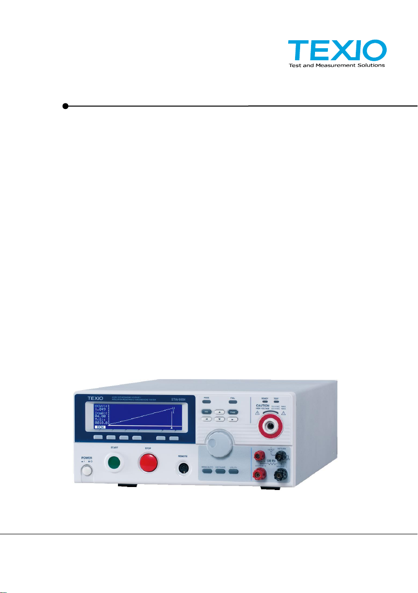
1.1 STW-9000 Series Overview
The STW-9000 Series Safety Testers are AC/DC withstanding voltage, insulation
resistance and ground bond safety testers.
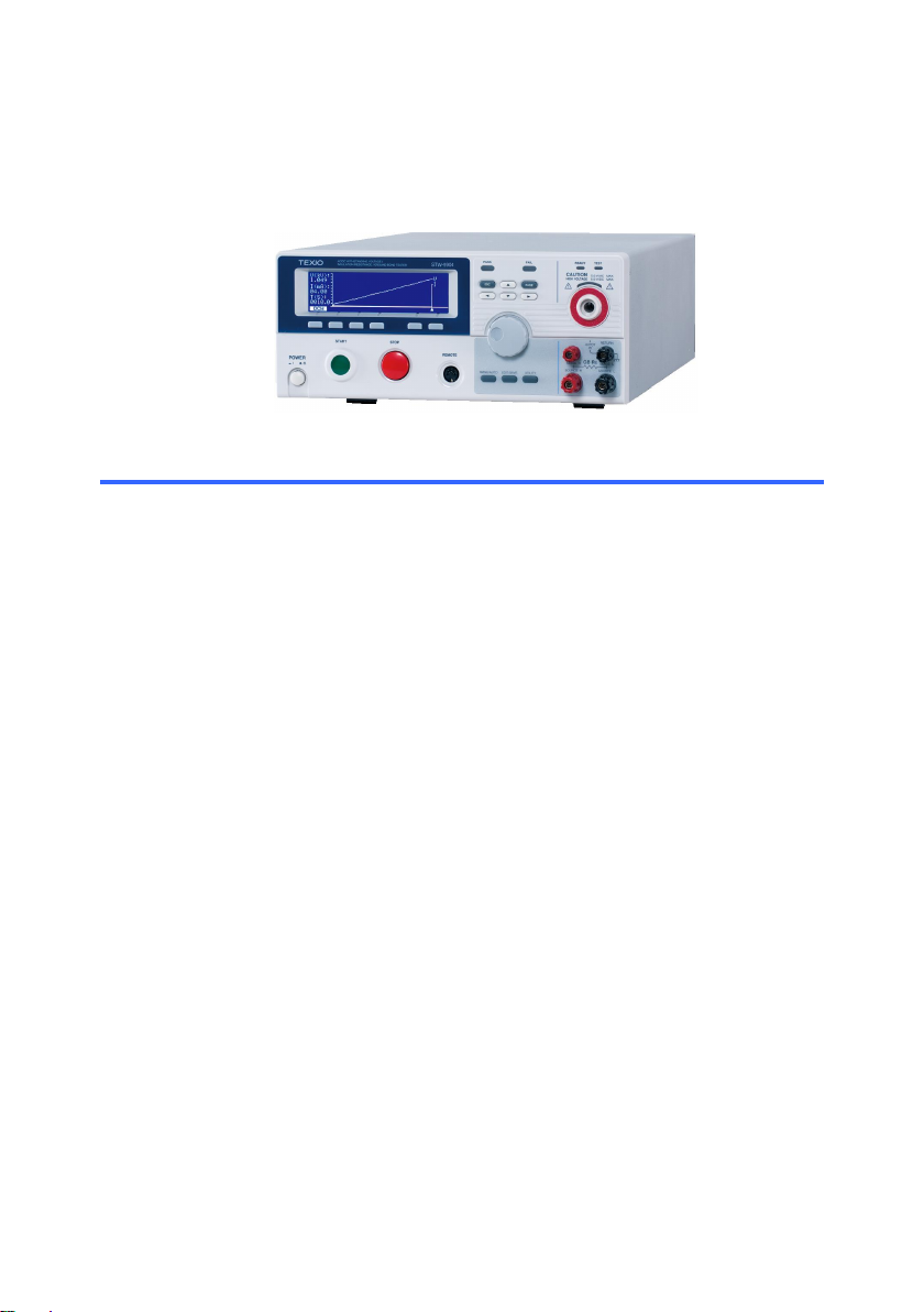
The STW-9901/9801 are AC withstanding voltage testers, the STW-9902/9802 are
AC/DC withstanding voltage testers and the STW-9903/9803 are AC/DC
withstanding voltage and insulation resistance testers. The STW-9904 includes all
the test functions of the other models as well as ground bond testing. All models
can operate at up to 5kVAC for AC withstanding voltage testing and at up to 6kVDC
for DC withstanding voltage testing (excluding the STW-9901/9801).
For the STW-9000 models, the testing terminals are also mirrored on the rear panel
for added safety and for more permanent safety testing environments. They also
include an innovative sweep function to view test results as a graph.
The STW-9000 Series can store up to 100 manual tests, as well as run up to 16
manual tests sequentially as an automatic test, allowing the safety testers to
accommodate any number of safety standards, including IEC, EN, UL, CSA, GB,
JIS and others.
Note: Throughout this user manual, the terms ACW, DCW, IR and GB refer to AC
Withstanding, DC Withstanding, Insulation Resistance and Ground Bond testing,
respectively.

2
1.2 Model Overview
Model name
ACW
DCW
IR
GB
Sweep
Rated Load
STW-9901
500VA/100W
STW-9902
500VA/100W
STW-9903
500VA/100W
STW-9904
500VA/100W
STW-9801
200VA/50W
STW-9802
200VA/50W
STW-9803
200VA/50W
1.3 Main Features
Performance
ACW: 5kVAC
DCW: 6kVDC
IR: 50V~1000V (50V steps)
GB: 3A~32A (STW-9904)
Features
Ramp up time control
Safety discharge
100 test conditions (MANU mode)
100 automatic tests (AUTO mode)
Over temperature, voltage and current protection
Pass, Fail, Test, High Voltage and Ready indicators
PWM output (90% efficiency, increased reliability)
Interlock (configurable).
Sweep Function.
Interface
Remote control start/stop interface terminal
RS-232C/USB interface for programming
Optional GP-IB interface for programming
Signal I/O port for pass/fail/test monitoring and start/stop
control/interlock
1.4 Accessories
Standard
Accessories
Part number
Description
GHT-114
Test lead
Power cord
Region dependent
GTL-115
GB Test leads (STW-9904 only)
N/A
Remote terminal male plug
N/A
N/A
Interlock key
Accessories CD
(Instruction manual, USB Driver)

3
Optional
Accessories
Part number
Description
GHT-205
High Voltage Test Probe
GHT-113
High Voltage Test Pistol
GTL-232
RS-232C cable
GTL-248
GP-IB cable
GTL-247
USB cable(A-A)
GRA-417
Rack Adapter Panel (19”,4U)
(STW-9901/02/03/9801/9802/9803)
Options
Part number
Description
Opt.1 GP-IB Interface
GP-IB module
1.5 Package Contents
Check the contents before using the STW-9000.
Opening the box
Contents
(single unit)
STW-9000 unit
Accessories CD (Instruction manual, USB Driver)
Power cord x1 (region dependent)
GHT-114 test leads x1
GTL-115 test leads x1(STW-9904)
Remote terminal male plug
Interlock key
Note
Keep the packaging, including the box, polystyrene foam
and plastic envelopes should the need arise to return the
unit to TEXIO TECHNOLOGY.
4
1.6 Appearance
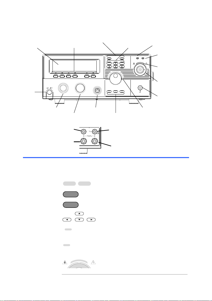
1.6.1 STW-9000 Front Panel
POWER
START STOP
REMOTE
MANU/ AUTO EDIT/SAVE UTILITY
ESC PAGE
Tester
HIGH VOLTAGE
CAUTION 5. 0kVAC MAX.
6. 0kVDC MAX.
AC/ DC Withstanding Voltage/
Insulation Resistance
RETURN
PASS FAIL READY TEST
PASS/FAIL indicators
Directional keysFunction keys
HIGH VOLTAGE
indicator
RETURN
terminal
REMOTE terminal
STOP button
START button
POWER
button
Display
Scroll wheel
Configuration keys
READY indicator
TEST indicator
HIGH VOLTAGE output
terminal
1.6.2 STW-9904 Front Panel
POWER
START STOP
REMOTE
MANU/AUTO EDIT/SAVE UTILITY
ESC PAGE
HIGH VOLTAGE
CAUTION 5.0 kVAC MAX.
6.0 kVDC MAX.
GB Rx
SENSE H
SOURCE H
SENSE L
SOURCE L
RETURN
PASS FAIL READY TEST
HI-POT
IR
G P T - 9 9 0 4 Tester
AC / DC Withstanding Voltage /
Insulation Resistance / Ground Bond
SOURCE L
SENSE L &
RETURN Terminal
SENSE H
SOURCE H
Display
240 X 64 dot matrix display (LCD)
Function keys
The function keys correspond to the soft-keys directly above
on the main display.
Pass/Fail
indicators
PASS
FAIL
The PASS and FAIL indicators light up upon
a PASS or FAIL test result at the end of a
manual test or automatic test.
ESC key
ESC
The ESC key is used to exit out of a menu
or cancel a setting.
PAGE key
PAGE
The PAGE key is used to view automatic
test information and test results.
Directional arrow
keys
The directional arrow keys are used to
navigate menus and parameter settings.
READY indicator
READY
The READY indicator is lit when the tester
is ready to begin testing. The STOP button
is used to put the tester into READY status.
TEST indicator
TEST
The TEST indicator is lit when a test is on.
The START button is used to put the tester
into TEST status.
HIGH VOLTAGE
indicator
HIGH VOLTAGE
CAUTION 5.0 kVAC MAX.
6.0 kVDC MAX.
The HIGH VOLTAGE indicator will light up
when an output terminal is active. Only
after the test has finished or stopped will
the indicator turn off.
5
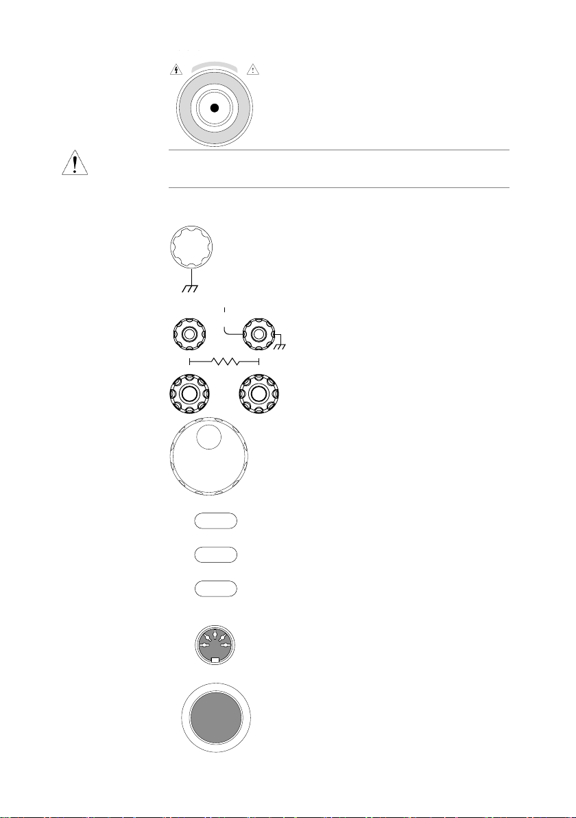
HIGH VOLTAGE
output terminal
HIGH VOLTAGE
CAUTION 5.0 kVAC MAX.
6.0 kVDC MAX.
The HIGH VOLTAGE terminal output is
used for outputting the testing voltage. The
terminal is recessed for safety. This
terminal is used in conjunction with the
RETURN terminal.
WARNING
USE EXTREME CAUTION.
Do not touch the HIGH VOLTAGE terminal during testing.
RETURN terminal
Except STW-9904
RETURN
The RETURN terminal is used for IR,
DCW and ACW tests.
RETURN, SENSE
and SOURCE
terminals
Only STW-9904
SOURCE H
SENSE H
SOURCE L
SENSE L
GB Rx
RETURN
HI-POT
IR
The RETURN terminal is used for IR,
DCW and ACW tests.
The SOURCE H, SOURCE L, SENSE
H and SENSE L terminals are used
for GB tests.
Scroll wheel
The scroll wheel is used to edit parameter
values.
UTILITY key
UTILITY
Used to enter the MANU Utility or Common
Utility menu.
EDIT/SAVE key
EDIT/SAVE
Used to start editing MANU/AUTO tests as
well as save settings and parameters.
MANU/AUTO key
MANU/AUTO
The MANU/AUTO key is used to select
manual tests (MANU) or automatic tests
(AUTO).
REMOTE terminal
REMOTE
The REMOTE terminal is used to connect
to a remote controller.
STOP button
STOP
The STOP button is used to stop/cancel
tests. The STOP button will also put the
safety tester in the READY status to begin
testing.

6
START button
START
The START button is used to start tests.
The START button can be used to start
tests when the tester is in the READY
status. Pressing the START button will put
the tester in the TEST status.
POWER switch
POWER
Turns the power on. The safety tester will
always start up with the last test setting
from when the instrument was last powered
down.
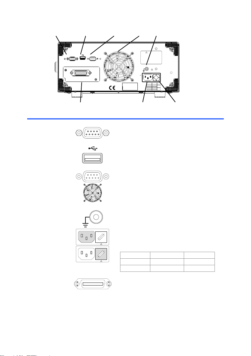
1.6.3 STW-9901/9902/9903 Rear Panel
TO AVOID ELECTRIC SHOCK THE POWER CORD
PROTECTIVE GROUNDING CONDUCTOR MUST BE
ONLY WITHSPECIFIEDTYPE AND RATEDFUSE.
NO OPERATOR SERVICEABLE COMPONENTS INSIDE.
DO NOT REMOVE COVERS. REFER SERVICING TO
FORCONTINUEDFIRE PROTECTION.REPLACE
CONNECTED TO GROUND.
QUALIFIED PERSONNEL.
WARNING
AC
LINE VOLTAGE
100V
230V
220V
120V
SELECTION
207~250V
RANGE
90~110V
198~242V
108~132V
(50/60Hz)
250V
250V
T 10A
FUSE
T 6.3A
MAX.
1000VA
GND
ENSURE THE POWER IS REMOVED FROM
THE INSTRUMENT BEFORE REPLACING THE FUSE
POWER
SIGNAL I / O RS232
GPIB
HIGH VOLTAGE
CAUTION
MAX.
6.0 kVDC
5.0 kVAC
RETURN
SER. NO. LB
Signal I/ O, RS232
& USB port Fan vents
Fuse selectorLine voltage
Optional GPIB port
High voltage terminal
GND
Return
terminal
1.6.4 STW-9904 Rear Panel
TO AVOID ELECTRIC SHOCK THE POWER CORD
PROTECTIVE GROUNDING CONDUCTOR MUSTBE
ONLY WITHSPECIFIEDTYPE AND RATED FUSE.
NO OPERATOR SERVICEABLE COMPONENTS INSIDE.
DO NOT REMOVE COVERS. REFER SERVICING TO
FORCONTINUEDFIRE PROTECTION. REPLACE
CONNECTED TO GROUND.
QUALIFIED PERSONNEL.
WARNING
AC
LINE VOLTAGE
100V
230V
220V
120V
SELECTION
207~250V
RANGE
90~110V
198~242V
108~132V
(50/60Hz)
250V
250V
T 10A
FUSE
T 6.3A
MAX.
1000VA
GND
ENSURE THE POWER IS REMOVED FROM
THE INSTRUMENT BEFORE REPLACING THE FUSE
POWER
SIGNAL I / O RS232
GPIB
GB Rx
SENSE H
SOURCE H
SENSE L
SOURCE L
RETURN
HI-POT
IR
HIGH VOLTAGE
CAUTION
MAX.
6.0 kVDC
5.0 kVAC
SER. NO. LB
High voltage terminal
Signal I/ O, RS232
& USB port Fan vents
Fuse selectorLine voltage
Optional GPIB port
GND
Return, Sense
and Source
terminals
7
1.6.5 STW-9801/9802/9803 Rear Panel
SIGNAL I/O USB A port RS-232Cport Fan
Fuse selector
Line voltage
Optional GP-IB port
GND
TO AVOID ELECTRIC SHOCK THE POWER CORD
PROTECTIVE GROUNDING CONDUCTOR MUST BE
ONLY WITH SPECIFIED TYPE AND RATED FUSE .
NO OPERATOR SERVICEABLE COMPONENTS INSIDE
.
DO NOT REMOVE COVERS REFER SERVICING TO
FOR CONTINUED FIRE PROTECTION .
REPLACE
CONNECTED TO GROUND .
QUALIFIED PERSONNEL.
WARNING
AC
LINEVOLTAGE
100V
230V
220V
120V
SELECTION
207~250V
RANGE
90~110V
198~242V
108~132V
(50/60 Hz)
T5A
250V
FUSE
POWER MAX.
500VA
GND
SIGNAL I/O RS232
SER. NO .LB
ENSURE THEPOWERISREMOVED FROM
THEINSTRUMENTBEFOREREPLACING THEFUSE
GPIB
T2.5A
250V
SIGNAL I/O port
SIGNAL I / O
The SIGNAL I/O port is used to monitor the
tester status (PASS, FAIL, TEST) and input
(START/ STOP signals). It is also used with
the Interlock key.
USB A port
Used for remote control.
RS-232C interface
port
RS232
Used for remote control and firmware
updates.
Fan/Fan Vents
Exhaust fan. Allow enough room for the fan
to vent. Do not block the fan openings.
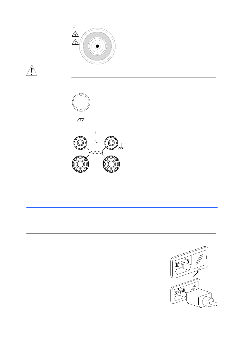
GND
GND
Connect the GND (ground) terminal to the
earth ground.
Line voltage input
220
230
100
120
Line voltage input: 100/120/220/230VAC
±10%
Line voltage fuse
220
230
100
120
Line voltage selector and fuse:
STW-9900
STW-9800
100V/120V
T10A 250V
T5A 250V
220V/230V
T6.3A 250V
T2.5A 250V
Optional GP-IB
port
GPIB
Optional GP-IB interface for remote control.
8
HIGH VOLTAGE
output terminal
CAUTION
HIGH VOLTAGE
MAX.
5.0 kVAC
6.0 kVDC
The HIGH VOLTAGE terminal output
is used for outputting the testing
voltage.
WARNING
USE EXTREME CAUTION.
Do not touch the HIGH VOLTAGE terminal during testing.
RETURN terminal
STW-9901/9902/9903
RETURN
The RETURN terminal is used for IR,
DCW and ACW tests.
RETURN/
SENSE and
SOURCE
terminals
Only STW-9904
GB Rx
SENSE H
SOURCE H
SENSE L
SOURCE L
RETURN
HI-POT
IR
The RETURN terminal is used for IR,
DCW and ACW tests.
The SOURCE L/H AND SENSE L/H
terminals are for GB tests only.
1.7 Set Up
1.7.1 Line Voltage Connection and Power Up
Background
Before powering up the STW-9000 ensure the correct
voltage has been selected on the rear panel. The
STW-9000 supports line voltages of 100V/120V/220V and
230V.
Steps
1. Check the line voltage and the fuse in
the fuse holder.
Page 93
The desired line voltage should line up
with the arrow on the fuse holder.
220
100
120
230
2. Connect the power cord to theAC
voltage input.
22
0
100
120
230

9
3. If the power cord does not have an
earth ground, ensure the ground
terminal is connected to an earth
ground.
GND
Warning
Ensure the power cord is connected to an earth ground.
Failure could be harmful to the operator and instrument.
4. Press the Power button.
POWER
5. When the unit is powering up, all the LED indicators will
light. Check to make sure all 5 LED indicators are working.
6. Check to make sure the System Self-Test passes without
errors.
S y s e mt
H a r w a rd e C
h
C h e c i g . .n .
F i r w a rm e C h
SYS T E
SM E L F T E
S T
k
e c i g . .n .k
e c i g . .n .k
After the System Self-Test completes, the tester will go
into VIEW status and be ready to operate.
I R G BA CW D CW
E
F R E Q = 0 H z6
0
100k V
EIV
MT I E = 0 0 1 . 0 SR
0 0 m AER F =# 0 .0
1 . 0 0 m AIH ES = 0T
0 0 . 1 S0A M P =R
W
VIEW status
MM A UN N A_2M A N U = * * * - 0 0
m A
WARNING
See the Appendix on page 94 for details if a self-test error
is detected.
1.7.2 Installing the Optional GP-IB Card
Background
The optional GP-IB is a user-installable option. Follow the
instructions below to install the GP-IB card.
WARNING
Before installing the optional GP-IB card ensure the
STW-9000 is turned off and disconnected from power.
Steps
1. Remove the screws from the rear panel cover plate.

10
2. Insert the GP-IB card into the two slots on either side of
the opening. Push the card gently until it is fully inserted.
1.7.3 Workplace Precautions
Background
The STW-9000 is a high voltage instrument that outputs
dangerous voltages. The following section describes
precautions and procedures that must be followed to
ensure a safe work environment.
WARNING
The STW-9000 generates voltages in excess of 5kVAC or
6kVDC. Follow all safety precautions, warnings and
directions given in the following section when using the
instrument.
1. Only technically qualified personnel should be allowed to
operate the safety tester.
2. The operating workplace must be fully isolated, especially
when the instrument is in operation. The instrument
should be clearly labeled with appropriate warning
signage.
3. The operator should not wear any conductive materials,
jewelry, badges, or other items, such wrist watches.
4. The operator should wear insulation gloves for high
voltage protection.
5. Ensure the earth ground of the line voltage is properly
grounded.
6. Ensure any devices that are adversely affected by
magnetic fields are not placed near the tester.
This manual suits for next models
9
Table of contents
Other TEXIO Test Equipment manuals


