TEXIO DCS-4605 User manual

INSTRUCTION MANUAL
DIGITAL STORAGE OSCILLOSCOPE
DCS-4605
B71-0392-01

■ About a trademark, a registered trademark
A company name and the brand name mentioned in this instruction
manual are the trademark or the registered trademark of each
company or group in each country and region.
■ About this instruction manual
When copying the part or all of contents of this instruction manual,
seek the copyright holder.
In addition, the specifications of the product and the contents of
this instruction manual are subject to change without notice for
improvement. Please check to our website for the latest version.

Table of Contents
USING THE PRODUCT SAFELY.................................................Ⅰ-Ⅴ
1. GETTING STARTED......................................1
1-1. Main Features .............................................. 1
1-2. Panel Overview ............................................ 3
1-2-1. Front Panel...................................................................3
1-2-2. Rear Panel ...................................................................6
1-2-3. Display..........................................................................7
1-3. Setting up the Oscilloscope........................... 8
2. QUICK REFERENCE ................................... 11
2-1. Menu Tree and Shortcuts .............................11
2-1-1. Acquire key.................................................................11
2-1-2. CH1/CH2 key .............................................................12
2-1-3. Cursor key 1/2............................................................12
2-1-4. Cursor key 2/2............................................................13
2-1-5. Display key.................................................................13
2-1-6. Autoset key.................................................................14
2-1-7. Hardcopy key .............................................................14
2-1-8. Help key .....................................................................14
2-1-9. Horizontal menu key ..................................................14
2-1-10.Math key 1/2 (+/-).......................................................15
2-1-11.Math key 2/2 (FFT).....................................................15
2-1-12.Measure key...............................................................16
2-1-13.Run/Stop key..............................................................16
2-1-14.Save/Recall key 1/9 ...................................................17
2-1-15.Save/Recall key 2/9 ...................................................17
2-1-16.Save/Recall key 3/9 ...................................................18
2-1-17.Save/Recall key 4/9 ...................................................18
2-1-18.Save/Recall key 5/9 ...................................................18
2-1-19.Save/Recall key 6/9 ...................................................19
2-1-20.Save/Recall key 7/9 ...................................................19
2-1-21.Save/Recall key 8/9 ...................................................20
2-1-22.Save/Recall key 9/9 ...................................................20
2-1-23.Trigger key 1/5 ...........................................................21
2-1-24.Trigger key 2/5 ...........................................................21
2-1-25.Trigger key 3/5 ...........................................................22
2-1-26.Trigger key 4/5 ...........................................................22
2-1-27.Trigger key 5/5 ...........................................................23

2-1-28.Utility key 1/10 (Utility #1)..........................................23
2-1-29.Utility key 2/10 (Utility #2) ..........................................24
2-1-30.Utility key 3/10 (Utility #3) ..........................................24
2-1-31.Utility key 4/10 (Hardcopy -Save All).........................24
2-1-32.Utility key 5/10 (Hardcopy -Save Image)...................25
2-1-33.Utility key 6/10 (Probe compensation).......................25
2-1-34.Utility key 7/10 (Go-NoGo).........................................25
2-1-35.Utility key 8/10 (Data Logging 1/2).............................26
2-1-36.Utility key 9/10 (Data Logging 2/2).............................26
2-1-37.Utility key 10/10 (Self CAL Menu)..............................26
2-1-38.Default Settings..........................................................27
2-2. Built-in Help................................................ 28
3. MEASUREMENT ......................................... 29
3-1. Basic Measurements................................... 29
3-1-1. Activating a channel...................................................29
3-1-2. Using Autoset.............................................................30
3-1-3. Running and stopping the trigger...............................31
3-1-4. Changing the horizontal position and scale...............32
3-1-5. Changing the vertical position and scale...................33
3-1-6. Using the probe compensation signal .......................34
3-2. Automatic Measurements ............................ 36
3-2-1. Measurement items ...................................................36
3-2-2. Automatically measuring the input signals ................38
3-3. Cursor Measurements ................................. 39
3-3-1. Using the horizontal cursors......................................39
3-3-2. Using the vertical cursors...........................................40
3-4. Math Operations ......................................... 41
3-4-1. Overview ....................................................................41
3-4-2. Adding, subtracting or multiplying signals .................42
3-4-3. Using the FFT function...............................................43
3-5. Go No-Go Testing ....................................... 44
3-5-1. Overview ....................................................................44
3-5-2. Edit: NoGo When.......................................................44
3-5-3. Edit: Source................................................................45
3-5-4. Edit: NoGo Violation Conditions ................................45
3-5-5. Edit: Template (boundary) .........................................46
3-5-6. Run Go-NoGo Tests..................................................50
3-6. Data Logging .............................................. 51
3-6-1. Overview ....................................................................51
3-6-2. Edit: Source................................................................51
3-6-3. Edit: Setup Parameters..............................................52

3-6-4. Run Data logging .......................................................53
4. CONFIGURATION ....................................... 54
4-1. Acquisition ..................................................54
4-1-1. Selecting the acquisition mode..................................54
4-1-2. Real time vs Equivalent time sampling mode............56
4-2. Display........................................................56
4-2-1. Selecting vector or dot drawing..................................56
4-2-2. Accumulating the waveform.......................................57
4-2-3. Adjusting the display contrast ....................................57
4-2-4. Selecting the display grid...........................................58
4-3. Horizontal View ...........................................58
4-3-1. Moving the waveform position horizontally................58
4-3-2. Selecting the horizontal scale....................................59
4-3-3. Selecting the waveform update mode .......................59
4-3-4. Zooming the waveform horizontally...........................60
4-3-5. Viewing waveforms in the X-Y mode.........................61
4-4. Vertical View (Channel)................................62
4-4-1. Moving the waveform position vertically....................62
4-4-2. Selecting the vertical scale ........................................62
4-4-3. Selecting the coupling mode......................................62
4-4-4. Inverting the waveform vertically................................63
4-4-5. Limiting the waveform bandwidth...............................64
4-4-6. Probe attenuation level and type ...............................64
4-5. Trigger ........................................................65
4-5-1. Trigger type................................................................65
4-5-2. Trigger parameter ......................................................65
4-5-3. Configuring the edge trigger ......................................67
4-5-4. Configuring the video trigger......................................68
4-5-5. Configuring the pulse width trigger ............................70
4-5-6. Manually triggering the signal....................................71
4-6. Remote Control Interface .............................72
4-7. Control with the “FreeWave” .........................73
4-7-1. System requirements.................................................73
4-7-2. Icon.............................................................................73
4-7-3. Connect screen..........................................................74
4-7-4. Image screen..............................................................75
4-7-5. Data screen................................................................76
4-7-6. Command screen.......................................................77
4-8. System Settings ..........................................78
4-8-1. Viewing the system information.................................78
4-8-2. Selecting the language...............................................78

5. SAVE/RECALL............................................ 79
5-1. File Structures ............................................ 79
5-1-1. Display image file format............................................79
5-1-2. Waveform file format..................................................79
5-1-3. Setup file format.........................................................81
5-1-4. Using the USB file utilities..........................................82
5-2. Quick Save (HardCopy)............................... 84
5-3. Save .......................................................... 85
5-3-1. File type/source/destination.......................................85
5-3-2. Saving the panel settings...........................................86
5-3-3. Saving the waveform .................................................87
5-3-4. Saving the display image...........................................88
5-3-5. Saving all....................................................................88
5-4. Recall......................................................... 90
5-4-1. File type/source/destination.......................................90
5-4-2. Recalling the default panel settings...........................90
5-4-3. Recalling a reference waveform to the display..........91
5-4-4. Recalling panel settings.............................................92
5-4-5. Recalling a waveform.................................................93
6. MAINTENANCE........................................... 94
6-1. Vertical Resolution Calibration..................... 94
6-2. Probe Compensation................................... 95
7. APPENDIX .................................................. 97
7-1. Fuse Replacement ...................................... 97
7-2. DCS-4605 Specifications............................. 98
7-2-1. Common specifications..............................................98
7-2-2. Probe Specifications................................................100
7-3. Dimensions................................................101
7-4. FAQ ..........................................................102

I
USING THE PRODUCT SAFELY
■Preface
To use the product safely, read this instruction manual to the end.
Before using this product, understand how to correctly use it.
If you read this manual but you do not understand how to use it, please
ask us or your local dealer. After you read this manual, save it so that you
can read it, anytime as requied.
■Pictorial indication
This instruction manual and product show the warning and caution items
required to safely use the product. The following pictorial indication and
warning character indication are provided.
<Pictorial indication>
Some part of this product or the instruction manual
may shows this pictorial indication. In this case, if the
product is incorrectly used in that part, a serious
danger may be brought about on the user’s body or
the product.
To use the part with this pictorial indication, be sure to
refer to this instruction manual.
WARNING
!
If you use the product, ignoring this indication, you
may get killed or seriously injured. This indication
shows that the warning item to avoid the danger is
provided.
CAUTION
!
If you incorrectly use the product, ignoring this
indication, you may get slightly injured or the product
may be damaged. This indication shows that the
caution item to avoid the danger is provided.
Please be informed that we are not responsible for any damages to the user or
to the third person, arising from malfunctions or other failures due to wrong
use of the product or incorrect operation, except such responsibility for
damages as required by law.

II
USING THE PRODUCT SAFELY
WARNING
!
CAUTION
!
■Do not remove the product’s covers and panels
Never remove the product’s covers and panels for any purpose.
Otherwise, the user’s electric shock or fire may be incurred.
■Warning on using the product
Warning items given below are to avoid danger to user’s body and life and
avoid the damage or deterioration of the product.
Use the product, observing the following warning andcaution items.
■Warning items on power supply
●Power supply voltage
The rated power supply voltages of the product are 100, 120, 220 and
240VAC. The rated power supply voltage for each product should be
confirmed by reading the label attached on the back of the product or
by the “rated” column shown in this instruction manual.
The specification of power cord attached to the products is rated to
125VAC for all products which are designed to be used in the areas
where commercial power supply voltage is not higher than 125VAC.
Accordingly, you must change the power cord if you want to use the
product at the power supply voltage higher than 125VAC. If you use
the product without changing power cord to 250VAC rated one,
electric shock or fire may be caused.
When you used the product equipped with power supply voltage
switching system, please refer to the corresponding chapter in the
instruction manuals of each product.
●Power cord
(Important) The attached power cord set can be used for this
device only.
If the attached power cord is damaged, stop using the product and call
us or your local dealer. If the power cord is used without the damage
being removed, an electric shock or fire may be caused.
●Protective fuse
If an input protective fuse is blown, the product does not operate. For a
product with external fuse holder, the fuse may be replaced. As for
how to replace the fuse, refer to the corresponding chapter in this
instruction manual.
If no fuse replacement procedures are indicated, the user is not
permitted to replace it. In such case, keep the case closed and consult
us or your local dealer. If the fuse is incorrectly replaced, a fire may
occur.

III
USING THE PRODUCT SAFELY
■Warning item on Grounding
If the product has the GND terminal on the front or rear panel surface, be
sure to ground the product to safely use it.
■Warnings on Installation environment
●Operating temperature and humidity
Use the product within the operating temperature indicated in the “rating”
temperature column. If the product is used with the vents of the product
blocked or in high ambient temperatures, a fire may occur.
Use the product within the operating humidity indicated in the “rating”
humidity column. Watch out for condensation by a sharp humidity
change such as transfer to a room with a different humidity. Also, do not
operate the product with wet hands. Otherwise, an electric shock or fire
may occur.
●Use in gas
Use in and around a place where an inflammable or explosive gas or
steam is generated or stored may result in an explosion and fire. Do not
operate the product in such an environment.
Also, use in and around a place where a corrosive gas is generated or
spreading causes a serious damage to the product. Do not operate the
product in such an environment.
●Installation place
Avoid installing the product on inclined places or on places subject to
vibration. Otherwise, the product may slip or fall down to cause
damages or injury accidents.
■Do not let foreign matter in
Do not insert metal and inflammable materials into the product from its vent
and spill water on it. Otherwise, electric shock or fire may occur.
■Warning item on abnormality while in use
In abnormal situations, such as “smoke”, “fire”, “abnormal smell” or
“irregular noise” occur from the product while in use, stop using the product,
turn off the switch, and remove the power cord plug from the outlet. After
confirming that no other devices catch fire, ask us or your local dealer.
IV
USING THE PRODUCT SAFELY
■Warning Item for the Measurement
●When you measure a part of a high voltage, be careful not to touch a hand
to a measurement part directly. There is a risk of an electric shock.
●Be sure to connectthe probe or the cableand theground side of the input
connector to the ground potential (ground) of the substance measured.
Since the chassis of this instrument is connected to the ground of the
input block, connecting the earth lead of the probe to the potential
floating from the ground potential may result in the following:
Electric shock
A high current flows and damages the substance measured, this
instrument, and other connected device.
The following parts are connected to the chassis:
Probe for each channel and ground side of the input BNC connector
Grounding conductor of the accessory 3-core power cord
Ground pin for an interface signal
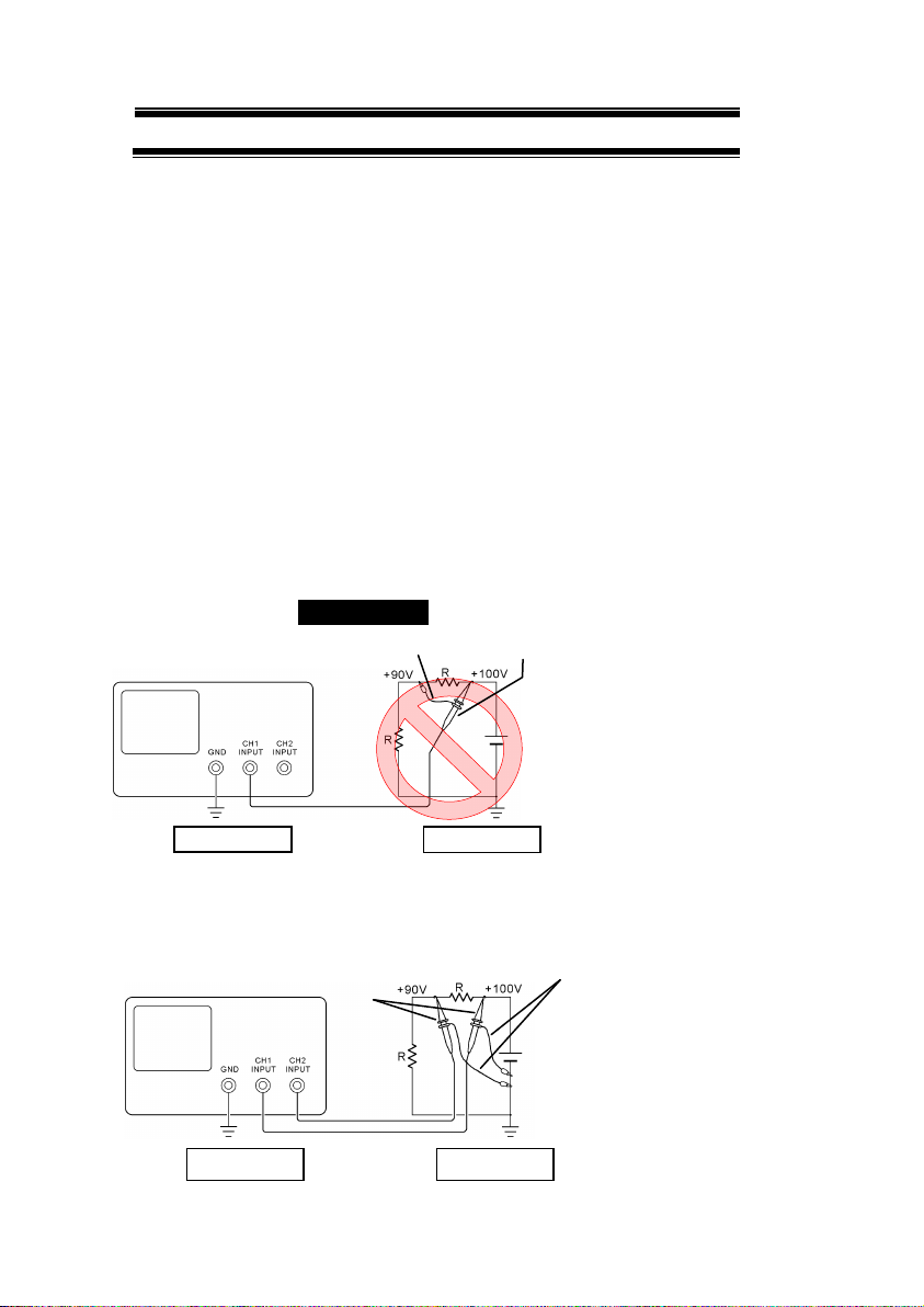
“Bad example” Prohibition
When measuring the floating potential, a differential method of
measurement is recommended ( refer to the figure below ).
“Good example”
At connecting as Bad
Example, +90V and chassis
are shorted, and damages
substance a measured.
Therefore do not make such
connection.
If the instrument is not
grounded, a potential of the
chassis is +90V.
Ground a chassis, in order to
prevent an electric shock
accident.
Setting of panel switches of an
oscilloscope
CH2 INV: ON (CH2 inverted)
ADD : ON (CH1+CH2)
Grounding
Oscilloscope
Earth Lead
Probe
Grounding
Oscilloscope
Grounding
Grounding
Earth Lead
Probe

V
USING THE PRODUCT SAFELY
■Input / Output terminals
Maximum input to terminal is specified to prevent the product from
being damaged. Do not supply input, exceeding the specifications
that are indicated in the "Rating" column in the instruction manual
of the product.
Also, do not supply power to the output terminals from the outside.
Otherwise, a product failure is caused.
■Calibration
Although the performance and specifications of the product are checked
under strict quality control during shipment from the factory, they may be
deviated more or less by deterioration of parts due to their aging or others.
It is recommended to periodically calibrate the product so that it is used
with its performance and specifications stable.
For consultation about the product calibration, ask us or your local dealer.
■Daily Maintenance
When you clean off the dirt of the product covers, panels, and knobs,
avoid solvents such as thinner and benzene. Otherwise, the paint may
peel off or resin surface may be affected.
To wipe off the covers, panels, and knobs, use a soft cloth with neutral
detergent in it. During cleaning, be careful that water, detergent, or other
foreign matters do not get into the product.
If a liquid or metal gets into the product, an electric shock and fire are
caused. During cleaning, remove the power cord plug from the outlet.
Use the product correctly and safely, observing the above warning and caution
items. Because the instruction manual indicates caution items even in
individual items, observe those caution items to correctly use the product.
If you have questions or comments about the instruction manual, ask us or E-
Mail us.

1
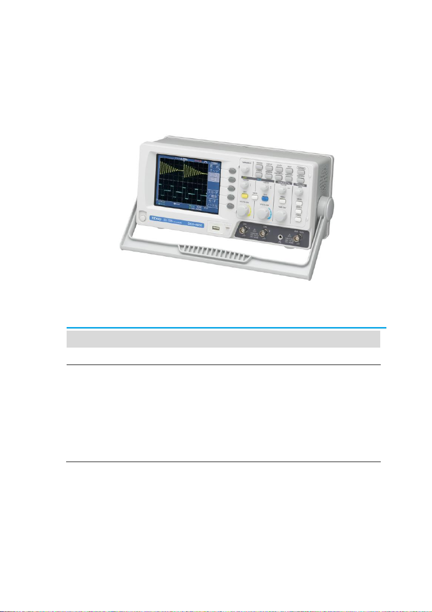
1. GETTING STARTED
The Getting started chapter introduces the oscilloscope’s main
features, appearance, and set up procedure.
1-1. Main Features
Model name
Frequency bandwidth
Input channels
DCS-4605
DC –50MHz (–3dB)
2
Performance
250MS/s real-time sampling rate
25GS/s equivalent-time sampling rate
Up to 10ns peak detection
2mV~10V vertical scale
1ns ~ 50s time scale

2
Features
5.7 inch color TFT display
Saving and recalling setups and waveforms
19 automatic measurements
Multi-language menu (12 languages)
Math operation: Addition, Subtraction, FFT
Data logging
Go-NoGo testing
Edge, video, pulse width trigger
Compact size: (W) 310 x (D) 140 x (H) 142 mm
Interface
USB 2.0 full-speed interface for saving and
recalling data
Calibration output
External trigger input
USB slave interface for remote control
3
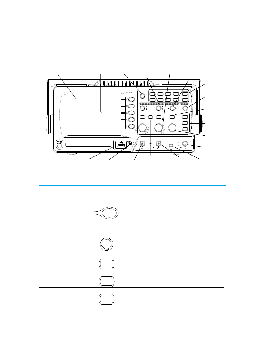
1-2. Panel Overview
1-2-1. Front Panel
LCD
Display Function
keys VARIABLE
knob
Menu keys
Trigger
LEVEL knob
Trigger
keys
Ground
Terminal
CH1
terminal
USB port CH2
terminal
Probe
compensation
output
EXT TRIG
terminal
Power
switch
Horizontal
POSITION
knob
Horizontal
MENU key
TIME/DIV
knob
CH1/CH2/M
ATH keys
Vertical
POSITION
knob
VOLTS/DIV
knob
VOLTS/ DIV VOLTS/ DIV TIME/DIV
CH1 MATH CH2 MENU MENU
Acquire Display Utility Help
Run/Stop
VARIABLE
FORCE
Autoset
Cursor
SINGLE
HardcopyMeasure Save/Recall
LEVEL
VERTICAL HORIZONTAL TRIGGER
CH1
CAT300V
MW15pF
MAX. 300Vpk
1
CH2 EXT TRIG
CAT300V
MW15pF
MAX. 300Vpk
1
X Y
/
LCD display
TFT color, 320 x 234 resolution, wide angle view
LCD display.
Function keys:
F1 (top) to
F5 (bottom)
Activates the functions which
appear in the left side of the LCD
display.
Variable knob
VARIABLE
Increases or decreases values
and moves to the next or previous
parameter.
Acquire key
Acquire
Configures the acquisition mode
(page 54).
Display key
Display
Configures the display settings
(page 56).
Cursor key
Cursor
Runs cursor measurements
(page 39).

4
Utility key
Utility
Configures the Hardcopy function
(page 84), shows the system
status (page 78), selects the menu
language (page 78), runs the self
calibration (page 94), configures
the probe compensation signal
(page 95),
Help key
Help
Shows the Help contents on the
display (page 28).
Autoset key
Autoset
Automatically configures the
horizontal, vertical, and trigger
settings according to the input
signal (page 30).
Measure key
Measure
Configures and runs automatic
measurements (page 36).
Save/Recall key
Save/Recall
Saves and recalls images,
waveforms, or panel settings
(page 79).
Hardcopy key
Hardcopy
Stores images, waveforms, or
panel settings to USB (page 84).
Run/Stop key
Run/Stop
Runs or stops triggering (page 31).
Trigger level
knob
LEVEL
TRIGGER
Sets the trigger level (page 65).
Trigger menu
key
MENU
Configures the trigger settings
(page 65).
Single trigger
key
SINGLE
Selects the single triggering mode
(page 71).
Trigger force key
FORCE
Acquires the input signal once
regardless of the trigger condition
at the time (page 71).
Horizontal menu
key
MENU
Configures the horizontal view
(page 58).
5
Horizontal
position knob
Moves the waveform horizontally
(page 58).
TIME/DIV knob
TIME/DIV
Selects the horizontal scale (page
59).
Vertical position
knob
Moves the waveform vertically
(page 62).
CH1/CH2 key
CH 1
Configures the vertical scale and
coupling mode for each channel
(page 62).
VOLTS/DIV
knob
VOLTS/DIV
Selects the vertical scale (page
62).
Input terminal
CH1
Accepts input signals: 1MΩ±2%
input impedance, BNC terminal.
Ground terminal
Accepts the DUT ground lead to
achieve a common ground.
MATH key
MATH
Performs math operations (page
41).
USB port
Facilitates transferring waveform
data, display images, and panel
settings (page 79).
Probe
compensation
output
Outputs a 2Vp-p, square signal for
compensating the probe (page 95)
or demonstration.
External trigger
input
EXT TRIG
Accepts an external trigger signal
(page 65).
Power switch
Powers the oscilloscope on or off.

6
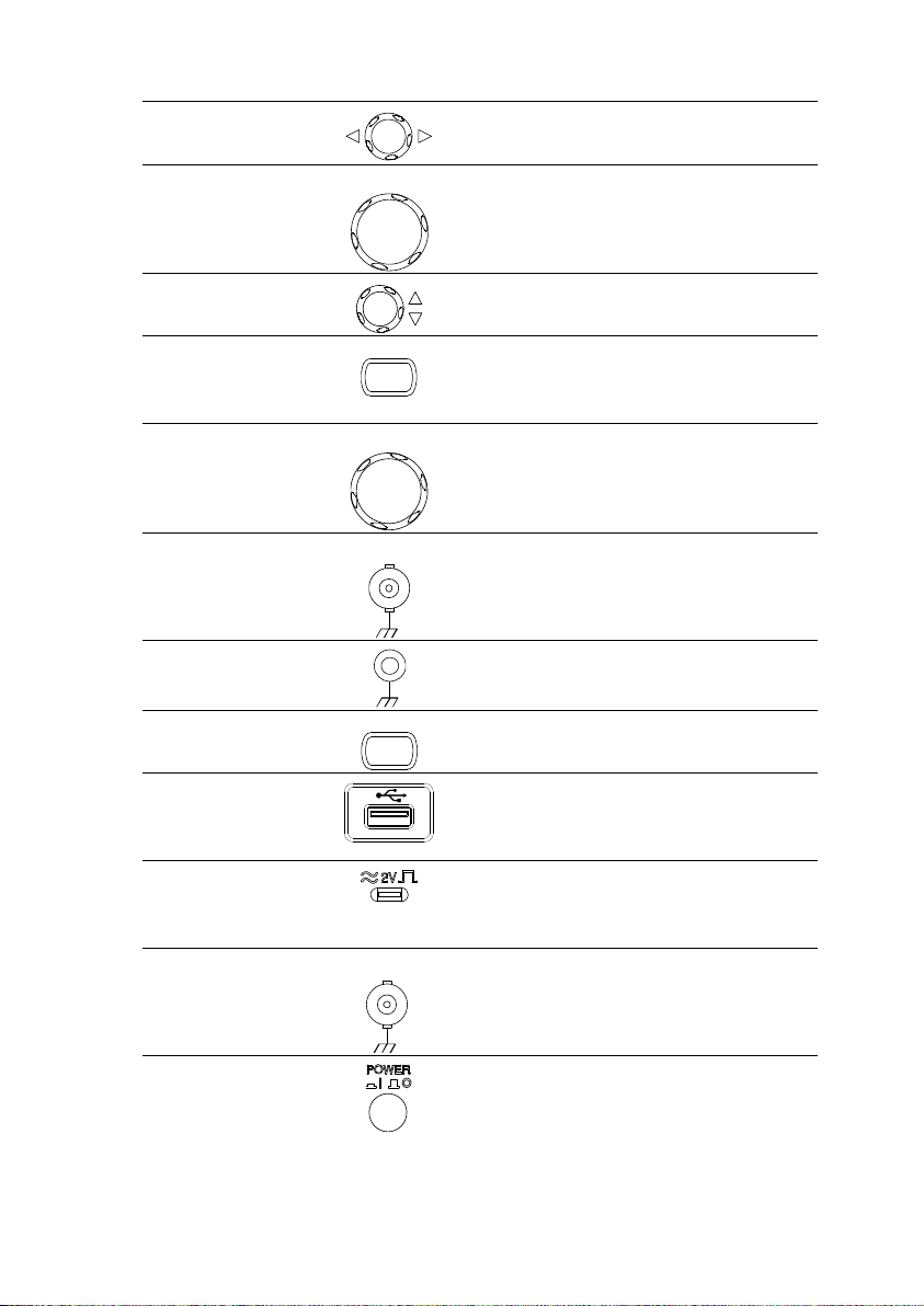
1-2-2. Rear Panel
LINE VOLTAGE AC 100 240V
FUSE RATING
RANGE
T1A 250V
FREQUENCY 50 60Hz
POWER MAX. 18W 40VA
USB portCAL outputPower cord socketFuse socket
Security lock
slot
Power cord
socket
Fuse socket
Power cord socket accepts the AC
mains, 100 ~ 240V, 50/60Hz.
The fuse socket holds the AC main
fuse, T1A/250V.
For the fuse replacement
procedure, see page 97.
USB slave port
Accepts a type B (slave) male USB
connector for remote control of the
oscilloscope (page 71).
Calibration
output
Outputs the calibration signal used
in vertical scale accuracy calibration
(page 94).
Security lock slot
Standard laptop security lock slot for
ensuring the security.

7
1-2-3. Display
Waveform marker
Vertical status Horizontal status Frequency Trigger condition
Waveform position Trigger status Acquisition
Menu
Waveforms
Channel 1: Yellow
Channel 2: Blue
Trigger status
Trig’d
A signal is being triggered
Trig?
Waiting for a trigger condition
Auto
Updating the input signal regardless
of trigger conditions
STOP
Triggering is stopped
For trigger setting details, see page 65.
Input signal
frequency
Updates the input signal frequency (the trigger
source signal) in real-time.
“< 2Hz” Indicates that the signal frequency is less
than the lower frequency limit (2Hz) and thus not
accurate.
Trigger
configuration
Shows the trigger source, type, and slope. In case
of the Video trigger, shows the trigger source and
polarity.
Horizontal status
Vertical status
Shows the channel configurations: coupling mode,
vertical scale, and horizontal scale.

8
1-3. Setting up the Oscilloscope
Background
This section describes how to set up the
oscilloscope properly including adjusting the
handle, connecting a signal, adjusting the scale,
and compensating the probe. Before operating the
oscilloscope in a new environment, run these steps
to make sure the oscilloscope is functionally stable.
Procedure
1. Pull both bases of
the handle out
slightly.
2. Turn to one of the three
preset positions.
3. Connect the power cord.
4. Press the power switch. The
display will become active in
approximately 10 seconds.
5. Reset the system by
recalling the factory settings.
Press the Save/Recall key,
then Default Setup. For
details regarding the factory
settings, see page 27.
Default
Setup
Save/Recall
6. Connect the probe between the Channel1 input
terminal and probe compensation signal output
(2Vp-p, 1kHz square wave).
Other manuals for DCS-4605
1
Table of contents
Other TEXIO Test Equipment manuals


