TEXIO DCS-9730 User manual
INSTRUCTION MANUAL
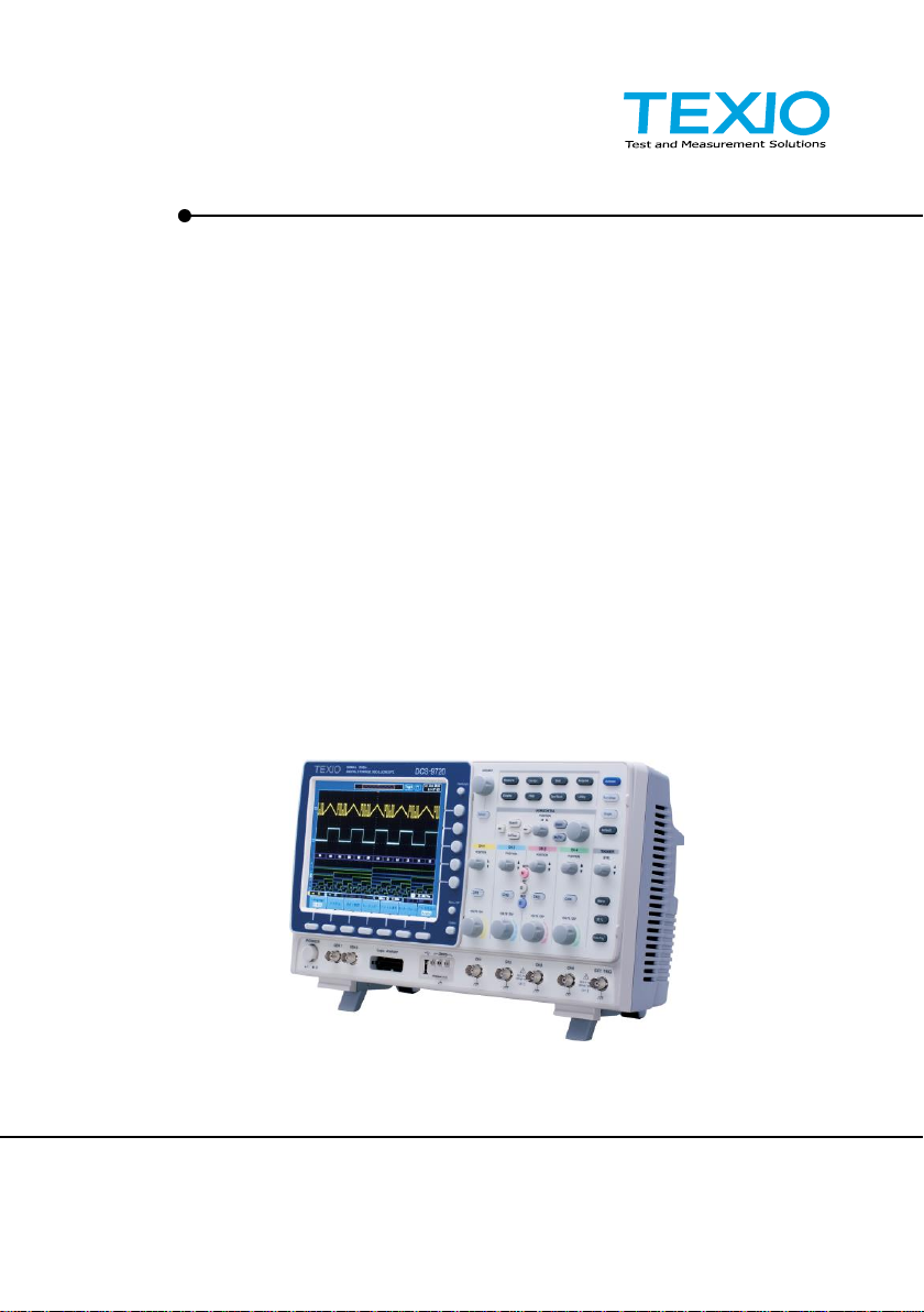
DIGITAL STORAGE OSCILLOSCOPE
DCS-9700 SERIES
DCS-9730
DCS-9730D
DCS-9720
DCS-9720D
DCS-9710
DCS-9710D
DCS-9707
DCS-9707D
B71-0206-11

■ About a trademark, a registered trademark
A company name and the brand name mentioned in this instruction
manual are the trademark or the registered trademark of each
company or group in each country and region.
■ About this instruction manual
When copying the part or all of contents of this instruction manual,
seek the copyright holder.
In addition, the specifications of the product and the contents of
this instruction manual are subject to change without notice for
improvement. Please check to our website for the latest version.
■ About export
When export or ship the product to overseas, please confirm laws
and regulations about the export.

Table of Contents
USING THE PRODUCT SAFELY...................................................Ⅰ-Ⅴ
1. GETTING STARTED................................................................... 1
1-1. Main Features ...................................................................... 1
1-2. Accessories.......................................................................... 3
1-3. Panel Overview .................................................................... 4
1-3-1. Front Panel........................................................................................ 4
1-3-2. Rear Panel ...................................................................................... 10
1-3-3. Display............................................................................................. 12
1-4. Set Up ............................................................................... 14
1-4-1. Tilt Stand......................................................................................... 14
1-4-2. Module Installation .......................................................................... 15
1-4-3. Software Installation........................................................................ 16
1-4-4. Power Up......................................................................................... 16
1-4-5. First Time Use................................................................................. 17
1-4-6. How to Use This Manual ................................................................. 19
2. QUICK REFERENCE................................................................ 24
2-1. Menu Tree / Operation Shortcuts ......................................... 24
2-1-1. Convention...................................................................................... 24
2-1-2. Acquire Key..................................................................................... 25
2-1-3. Acquire Key –Segments................................................................. 25
2-1-4. Autoset Key..................................................................................... 26
2-1-5. CH1 ~ 4 Key.................................................................................... 26
2-1-6. Cursor Key ...................................................................................... 26
2-1-7. Display Key ..................................................................................... 27
2-1-8. Help Key.......................................................................................... 27
2-1-9. Math Key......................................................................................... 28
2-1-10. Measure Key................................................................................. 29
2-1-11. Hardcopy Key................................................................................ 30
2-1-12. Run/Stop Key................................................................................ 30
2-1-13. REF Key........................................................................................ 30
2-1-14. Save/Recall Key............................................................................ 31
2-1-15. Test Key........................................................................................ 32
2-1-16. Test Key –Go-NoGo..................................................................... 32
2-1-17. Trigger Type Menu........................................................................ 33
2-1-18. Trigger Edge Menu........................................................................ 33
2-1-19. Trigger Delay Menu....................................................................... 33
2-1-20. Trigger Pulse Width Menu............................................................. 34
2-1-21. Trigger Video Menu....................................................................... 34
2-1-22. Trigger Pulse Runt Menu............................................................... 34
2-1-23. Trigger Rise & Fall Menu............................................................... 35
2-1-24. Trigger Timeout Menu................................................................... 35
2-1-25. Utility Key ...................................................................................... 36
2-1-26. Utility Key –I/O.............................................................................. 37
2-1-27. Utility Key –File Utilities................................................................ 37
2-1-28. Utility Key –Wave Generator - Demo Outputs.............................. 38
2-1-29. Search - Edge ............................................................................... 38

2-1-30. Search –Pulse Width.................................................................... 39
2-1-31. Search - Runt................................................................................ 39
2-1-32. Search –Rise/Fall Time................................................................ 40
2-1-33. Zoom Key...................................................................................... 40
2-1-34. Option Key..................................................................................... 41
2-2. Default Settings.................................................................. 42
2-3. Built-in Help ....................................................................... 43
3. MEASUREMENT...................................................................... 44
3-1. Basic Measurement ............................................................ 44
3-1-1. Channel Activation .......................................................................... 44
3-1-2. Autoset............................................................................................ 45
3-1-3. Run/Stop ......................................................................................... 46
3-1-4. Horizontal Position/Scale................................................................. 47
3-1-5. Vertical Position/Scale..................................................................... 48
3-2. Automatic Measurement...................................................... 49
3-2-1. Measurement Items......................................................................... 49
3-2-2. Add Measurement........................................................................... 53
3-2-3. Remove Measurement.................................................................... 54
3-2-4. Gated mode..................................................................................... 54
3-2-5. Display All mode.............................................................................. 55
3-2-6. High Low Function........................................................................... 56
3-2-7. Statistics.......................................................................................... 57
3-3. Cursor Measurement .......................................................... 59
3-3-1. Use Horizontal Cursors ................................................................... 59
3-3-2. Use Vertical Cursors ....................................................................... 61
3-4. Math Operation................................................................... 64
3-4-1. Overview ......................................................................................... 64
3-4-2. Addition/Subtraction/Multiplication/Division..................................... 65
3-4-3. FFT.................................................................................................. 66
3-4-4. Advanced Math ............................................................................... 68
3-4-5. Edit F(x)........................................................................................... 69
4. CONFIGURATION.................................................................... 70
4-1. Acquisition ......................................................................... 70
4-1-1. Select Acquisition Mode.................................................................. 70
4-1-2. Digital Filter ..................................................................................... 71
4-1-3. Show Waveform in XY Mode........................................................... 72
4-1-4. Set the Sampling Mode................................................................... 74
4-1-5. Set the Record Length..................................................................... 75
4-2. Segmented Memory Acquisition........................................... 76
4-2-1. Segments Display ........................................................................... 76
4-2-2. Set the Number of Segments.......................................................... 76
4-2-3. Run Segmented Memory................................................................. 77
4-2-4. Navigate Segmented Memory......................................................... 78
4-2-5. Segment Measurement................................................................... 78
4-2-6. Display All........................................................................................ 79
4-2-7. Automatic Measurement.................................................................. 80
4-2-8. Segment Info................................................................................... 82
4-3. Display............................................................................... 82

4-3-1. Display Waveform as Dots or Vectors............................................. 82
4-3-2. Set the Level of Persistence............................................................ 83
4-3-3. Set the Intensity Level..................................................................... 83
4-3-4. Set the Waveform Intensity Type .................................................... 84
4-3-5. Select Display Graticule .................................................................. 85
4-3-6. Freeze the Waveform (Run/Stop).................................................... 85
4-3-7. Turn Off Menu................................................................................. 86
4-4. Horizontal View .................................................................. 87
4-4-1. Move Waveform Position Horizontally............................................. 87
4-4-2. Select Horizontal Scale ................................................................... 87
4-4-3. Select Waveform Update Mode....................................................... 88
4-4-4. Zoom Waveform Horizontally.......................................................... 89
4-5. Vertical View (Channel)....................................................... 91
4-5-1. Move Waveform Position Vertically................................................. 91
4-5-2. Select Vertical Scale ....................................................................... 91
4-5-3. Select Coupling Mode..................................................................... 91
4-5-4. Input Impedance.............................................................................. 92
4-5-5. Invert Waveform Vertically............................................................... 92
4-5-6. Limit Bandwidth............................................................................... 93
4-5-7. Expand by Ground/Center............................................................... 93
4-5-8. Select Probe Type........................................................................... 94
4-5-9. Select Probe Attenuation Level....................................................... 94
4-5-10. Set the Deskew............................................................................. 95
4-6. Trigger ............................................................................... 95
4-6-1. Trigger Type Overview.................................................................... 95
4-6-2. Trigger Parameter Overview ........................................................... 97
4-6-3. Setup Holdoff Level....................................................................... 100
4-6-4. Setup Trigger Mode....................................................................... 101
4-6-5. Using the Edge Trigger.................................................................. 101
4-6-6. Using Advanced Delay Trigger...................................................... 102
4-6-7. Using Pulse Width (glitch) Trigger................................................. 103
4-6-8. Using Video Trigger....................................................................... 104
4-6-9. Pulse Runt trigger.......................................................................... 105
4-6-10. Using Rise and Fall (slope) Trigger............................................. 106
4-6-11. Using the Timeout Trigger........................................................... 107
4-7. Search ..............................................................................108
4-7-1. Configuring Search Events............................................................ 108
4-7-2. Copying Search Event To/From Trigger Events............................ 109
4-7-3. Search Event Navigation............................................................... 110
4-7-4. Save Search Marks....................................................................... 110
4-7-5. Setting/Clearing Single Search Events.......................................... 111
4-7-6. Play / Pause.................................................................................. 111
4-8. System Info / Language / Clock ..........................................113
4-8-1. Select Menu Language.................................................................. 113
4-8-2. View System Information............................................................... 113
4-8-3. Erase Memory............................................................................... 114
4-8-4. Turn the Buzzer On/Off................................................................. 115
4-8-5. Set Date and Time ........................................................................ 115

4-8-6. Demo Outputs............................................................................... 116
5. OPTIONAL SOFTWARE and APPS. .........................................118
5-1. Applications.......................................................................118
5-1-1. Overview ....................................................................................... 118
5-1-2. Running Applications..................................................................... 118
5-1-3. Uninstalling Applications................................................................ 118
5-1-4. Using Go-NoGo............................................................................. 119
5-2. Optional Software ..............................................................123
5-2-1. Activating Optional Software ......................................................... 123
5-2-2. Running Optional Software............................................................ 123
5-2-3. Uninstalling Optional Software ...................................................... 124
6. SAVE/RECALL........................................................................125
6-1. File Format/Utility ..............................................................125
6-1-1. Image File Format......................................................................... 125
6-1-2. Waveform File Format................................................................... 125
6-1-3. Spreadsheet File Format............................................................... 125
6-1-4. Setup File Format.......................................................................... 128
6-2. Create/Edit Labels .............................................................129
6-3. Save .................................................................................131
6-3-1. File Type/Source/Destination ........................................................ 131
6-3-2. Save Image................................................................................... 132
6-3-3. Save Waveform............................................................................. 133
6-3-4. Save Setup.................................................................................... 134
6-4. Recall ...............................................................................135
6-4-1. File Type/Source/Destination ........................................................ 135
6-4-2. Recall Default Panel Setting.......................................................... 136
6-4-3. Recall Waveform........................................................................... 137
6-4-4. Recall Setup.................................................................................. 138
6-5. Reference Waveforms........................................................139
6-5-1. Recall and Display Reference Waveforms.................................... 139
7. FILE UTILITIES ......................................................................141
7-1. File Navigation ..................................................................141
7-2. Create Folder ....................................................................143
7-3. Rename File......................................................................144
7-4. Delete File ........................................................................145
7-5. Copy File to USB ...............................................................145
8. HARDCOPY KEY ....................................................................147
8-1. Printer I/O Configuration ....................................................147
8-2. Print Output.......................................................................148
8-3. Save - Hardcopy Key .........................................................148
9. REMOTE CONTROL CONFIG..................................................150
9-1. Configure USB Interface ....................................................150
9-2. Configure RS-232C Interface .............................................151
9-3. Configure the Ethernet Interface.........................................152
9-4. Configure Socket Server ....................................................154
9-5. Configure GP-IB ................................................................155
9-6. USB/RS-232C Functionality Check .....................................156
9-7. Socket Server Functionality Check .....................................157

9-8. GP-IB Functionality Check .................................................159
9-9. Web Server Overview ........................................................161
10. MAINTENANCE ....................................................................163
10-1. How to use SPC function..................................................163
10-2. Vertical Accuracy Calibration ............................................164
10-3. Probe Compensation........................................................165
11. APPENDIX ............................................................................167
11-1. DCS-9700 Specifications..................................................167
11-1-1. Model-specific ............................................................................. 167
11-1-2. Common-specific......................................................................... 167
11-2. Probe Specifications ........................................................171
11-2-1. GTP-070B-4................................................................................ 171
11-2-2. GTP-150A-2................................................................................ 171
11-2-3. GTP-250A-2................................................................................ 172
11-2-4. GTP-350A-2................................................................................ 172
11-3. DCS-9700 Dimensions ....................................................173
11-4. FAQ.................................................................................174
I
USING THE PRODUCT SAFELY
■Preface
To use the product safely, read this instruction manual to the end.
Before using this product, understand how to correctly use it.
If you read this manual but you do not understand how to use it, please
ask us or your local dealer. After you read this manual, save it so that
you can read it, anytime as requied.
■Pictorial indication
This instruction manual and product show the warning and caution items
required to safely use the product. The following pictorial indication and
warning character indication are provided.
<Pictorial indication>
Some part of this product or the instruction
manual may shows this pictorial indication. In
this case, if the product is incorrectly used in that
part, a serious danger may be brought about on
the user’s body or the product.
To use the part with this pictorial indication, be
sure to refer to this instruction manual.
WARNING
!
If you use the product, ignoring this indication,
you may get killed or seriously injured. This
indication shows that the warning item to avoid
the danger is provided.
CAUTION
!
If you incorrectly use the product, ignoring this
indication, you may get slightly injured or the
product may be damaged. This indication shows
that the caution item to avoid the danger is
provided.
Please be informed that we are not responsible for any damages to the user
or to the third person, arising from malfunctions or other failures due to
wrong use of the product or incorrect operation, except such responsibility
for damages as required by law.

II
USING THE PRODUCT SAFELY
WARNING
!
CAUTION
!
■Do not remove the product’s covers and panels
Never remove the product’s covers and panels for any purpose.
Otherwise, the user’s electric shock or fire may be incurred.
■Warning on using the product
Warning items given below are to avoid danger to user’s body and life and
avoid the damage or deterioration of the product.
Use the product, observing the following warning andcaution items.
■Warning items on power supply
●Power supply voltage
The rated power supply voltages of the product are 100, 120, 220
and 240VAC. The rated power supply voltage for each product
should be confirmed by reading the label attached on the back of
the product or by the “rated” column shown in this instruction manual.
The specification of power cord attached to the products is rated to
125VAC for all products which are designed to be used in the
areas where commercial power supply voltage is not higher than
125VAC. Accordingly, you must change the power cord if you want
to use the product at the power supply voltage higher than 125VAC.
If you use the product without changing power cord to 250VAC
rated one, electric shock or fire may be caused.
When you used the product equipped with power supply voltage
switching system, please refer to the corresponding chapter in the
instruction manuals of each product.
●Power cord
(Important) The attached power cord set can be used for this
device only.
If the attached power cord is damaged, stop using the product and
call us or your local dealer. If the power cord is used without the
damage being removed, an electric shock or fire may be caused.
●Protective fuse
If an input protective fuse is blown, the product does not operate. For a
product with external fuse holder, the fuse may be replaced. As for
how to replace the fuse, refer to the corresponding chapter in this
instruction manual.
If no fuse replacement procedures are indicated, the user is not
permitted to replace it. In such case, keep the case closed and
consult us or your local dealer. If the fuse is incorrectly replaced, a
fire may occur.

III
USING THE PRODUCT SAFELY
■Warning item on Grounding
If the product has the GND terminal on the front or rear panel surface,
be sure to ground the product to safely use it.
■Warnings on Installation environment
●Operating temperature and humidity
Use the product within the operating temperature indicated in the
“rating” temperature column. If the product is used with the vents of
the product blocked or in high ambient temperatures, a fire may occur.
Use the product within the operating humidity indicated in the “rating”
humidity column. Watch out for condensation by a sharp humidity
change such as transfer to a room with a different humidity. Also, do
not operate the product with wet hands. Otherwise, an electric shock
or fire may occur.
●Use in gas
Use in and around a place where an inflammable or explosive gas or
steam is generated or stored may result in an explosion and fire. Do
not operate the product in such an environment.
Also, use in and around a place where a corrosive gas is generated or
spreading causes a serious damage to the product. Do not operate
the product in such an environment.
●Installation place
Avoid installing the product on inclined places or on places subject to
vibration. Otherwise, the product may slip or fall down to cause
damages or injury accidents.
■Do not let foreign matter in
Do not insert metal and inflammable materials into the product from its
vent and spill water on it. Otherwise, electric shock or fire may occur.
■Warning item on abnormality while in use
In abnormal situations, such as “smoke”, “fire”, “abnormal smell” or
“irregular noise” occur from the product while in use, stop using the
product, turn off the switch, and remove the power cord plug from the
outlet. After confirming that no other devices catch fire, ask us or your
local dealer.
IV
USING THE PRODUCT SAFELY
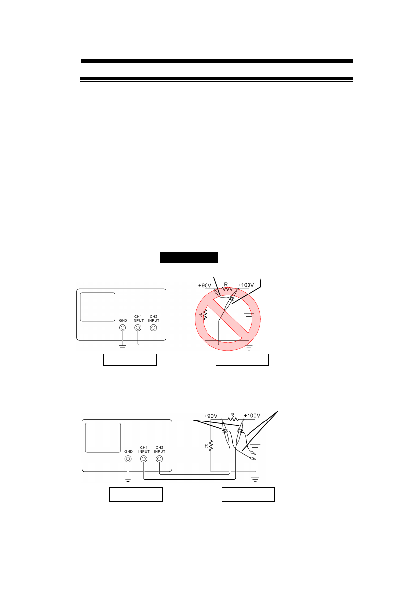
■Warning Item for the Measurement
●When you measure a part of a high voltage, be careful not to touch a
hand to a measurement part directly. There is a risk of an electric shock.
●Be sure to connectthe probe or the cable andthe ground side of the input
connector to the ground potential (ground) of the substance measured.
Since the chassis of this instrument is connected to the ground of the
input block, connecting the earth lead of the probe to the potential
floating from the ground potential may result in the following:
⚫Electric shock
⚫A high current flows and damages the substance measured, this
instrument, and other connected device.
The following parts are connected to the chassis:
⚫Probe for each channel and ground side of the input BNC connector
⚫Grounding conductor of the accessory 3-core power cord
⚫Ground pin for an interface signal
“Bad example” Prohibition
When measuring the floating potential, a differential method of
measurement is recommended ( refer to the figure below ).
“Good example”
At connecting as Bad
Example, +90V and chassis
are shorted, and damages
substance a measured.
Therefore do not make such
connection.
If the instrument is not
grounded, a potential of the
chassis is +90V.
Ground a chassis, in order to
prevent an electric shock
accident.
Setting of panel switches of an
oscilloscope
CH2 INV: ON (CH2 inverted)
ADD : ON (CH1+CH2)
Grounding
Oscilloscope
Earth Lead
Probe
Grounding
Oscilloscope
Grounding
Grounding
Earth Lead
Probe

V
USING THE PRODUCT SAFELY
■Input / Output terminals
Maximum input to terminal is specified to prevent the product
from being damaged. Do not supply input, exceeding the
specifications that are indicated in the "Rating" column in the
instruction manual of the product.
Also, do not supply power to the output terminals from the
outside.
Otherwise, a product failure is caused.
■Calibration
Although the performance and specifications of the product are
checked under strict quality control during shipment from the factory,
they may be deviated more or less by deterioration of parts due to their
aging or others.
It is recommended to periodically calibrate the product so that it is used
with its performance and specifications stable.
For consultation about the product calibration, ask us or your local
dealer.
■Daily Maintenance
When you clean off the dirt of the product covers, panels, and
knobs, avoid solvents such as thinner and benzene. Otherwise, the
paint may peel off or resin surface may be affected.
To wipe off the covers, panels, and knobs, use a soft cloth with neutral
detergent in it. During cleaning, be careful that water, detergent, or
other foreign matters do not get into the product.
If a liquid or metal gets into the product, an electric shock and fire are
caused. During cleaning, remove the power cord plug from the outlet.
Use the product correctly and safely, observing the above warning and
caution items. Because the instruction manual indicates caution items even
in individual items, observe those caution items to correctly use the product.
If you have questions or comments about the instruction manual, ask us or
E-Mail us.
1
1. GETTING STARTED
The Getting started chapter introduces the oscilloscope’s main
features, appearance, and set up procedure.
1-1. Main Features
Model name
Frequency
bandwidth
Input
channels
Real-time
Sampling Rate
DCS-9707
70MHz
4
2GSa/s
DCS-9710
100MHz
4
2GSa/s
DCS-9720
200MHz
4
2GSa/s
DCS-9730
300MHz
4
2GSa/s
DCS-9707D
70MHz
2
2GSa/s
DCS-9710D
100MHz
2
2GSa/s
DCS-9720D
200MHz
2
2GSa/s
DCS-9730D
300MHz
2
2GSa/s
Note
This instruction manual has been described as the
4ch model. In 2ch model, Can't set the ch3 and ch4.

2
Features
•8 inch TFT SVGA display.
•All models feature a real-time sampling rate of
2GSa/s and an equivalent time sampling rate of
100GSa/s.
•Deep memory: 2M points record length.
•Waveform capture rate of 80,000 waveforms
per second.
•Vertical sensitivity: 1mV/div~10V/div.
•Logic Analyzer module (optional): Adds 8 or 16
channel digital inputs and serial bus (I2C, SPI,
UART) and parallel bus triggering.
•DDS Function Generator module (optional).
•Segmented Memory: Optimizes the acquisition
memory to selectively capture only the
important signal details. Up to 2048 successive
waveform segments can be captured with a
time-tag resolution of 8ns. Segmented memory
can be used for both analog and digital
channels.
•Enhanced Search: Allows the scope to search
for a number of different signal events.
•On-screen Help.
•64 MB internal flash disk.
Interface
•USB host port: front and rear panel, for storage
devices.
•USB device port: rear panel, for remote control
or printing.
•Demo output
•GP-IB (optional)
•RS-232C port.
•Calibration output
•SVGA output and Ethernet port (optional)

3
1-2. Accessories
Standard
Accessories
Part number
Description
Power cord
N/A
region dependent
Passive
probe
GTP-070B-4
70MHz(DCS-9707 / DCS-9707D)
GTP-150B-4
150MHz(DCS-9710 / DCS-9710D)
GTP-250A-2
250MHz(DCS-9720 / DCS-9720D)
GTP-350A-2
350MHz(DCS-9730 / DCS-9730D)
Options
Option Number
Description
DS2-LAN
Ethernet & SVGA output
DS2-GPIB
GP-IB Interface
DS2-FGN
DDS Function Generator
DS2-08LA
8-Channel Logic Analyzer card with
8-Channel Logic Analyzer Probe
(GTL-08LA)
DS2-16LA
16-Channel Logic Analyzer card
with 16-Channel Logic Analyzer
Probe (GTL-16A)
Optional
Accessories
Part number
Description
GTL-110
Test lead, BNC to BNC heads
GTL-232
RS-232C cable, 9-pin Female to
9-pin Female, Null modem for PC
GTL-246
USB cable USB2.0A-B type cable
GTL-08LA
8Ch Logic Analyzer Testing Probe
GTL-16LA
16Ch Logic Analyzer Testing Probe
Drivers
USB driver
for Windows PC
LabVIEW driver

4
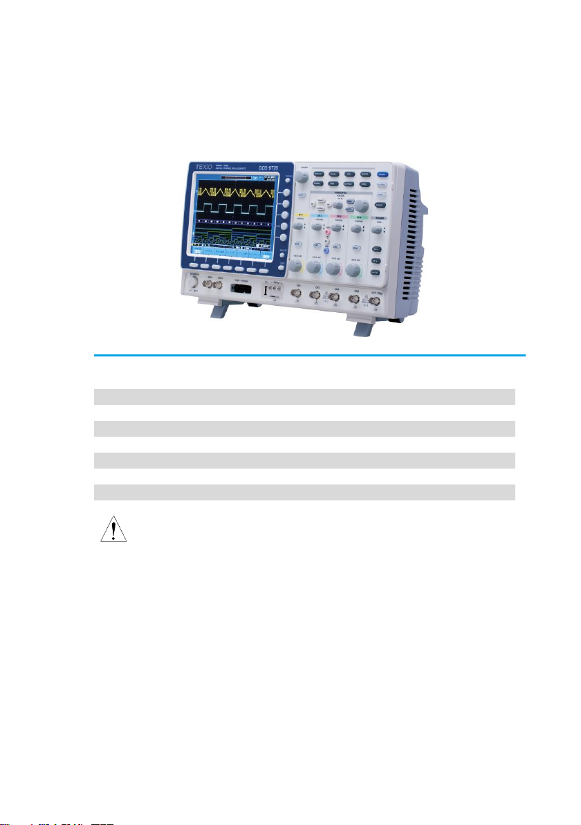
1-3. Panel Overview
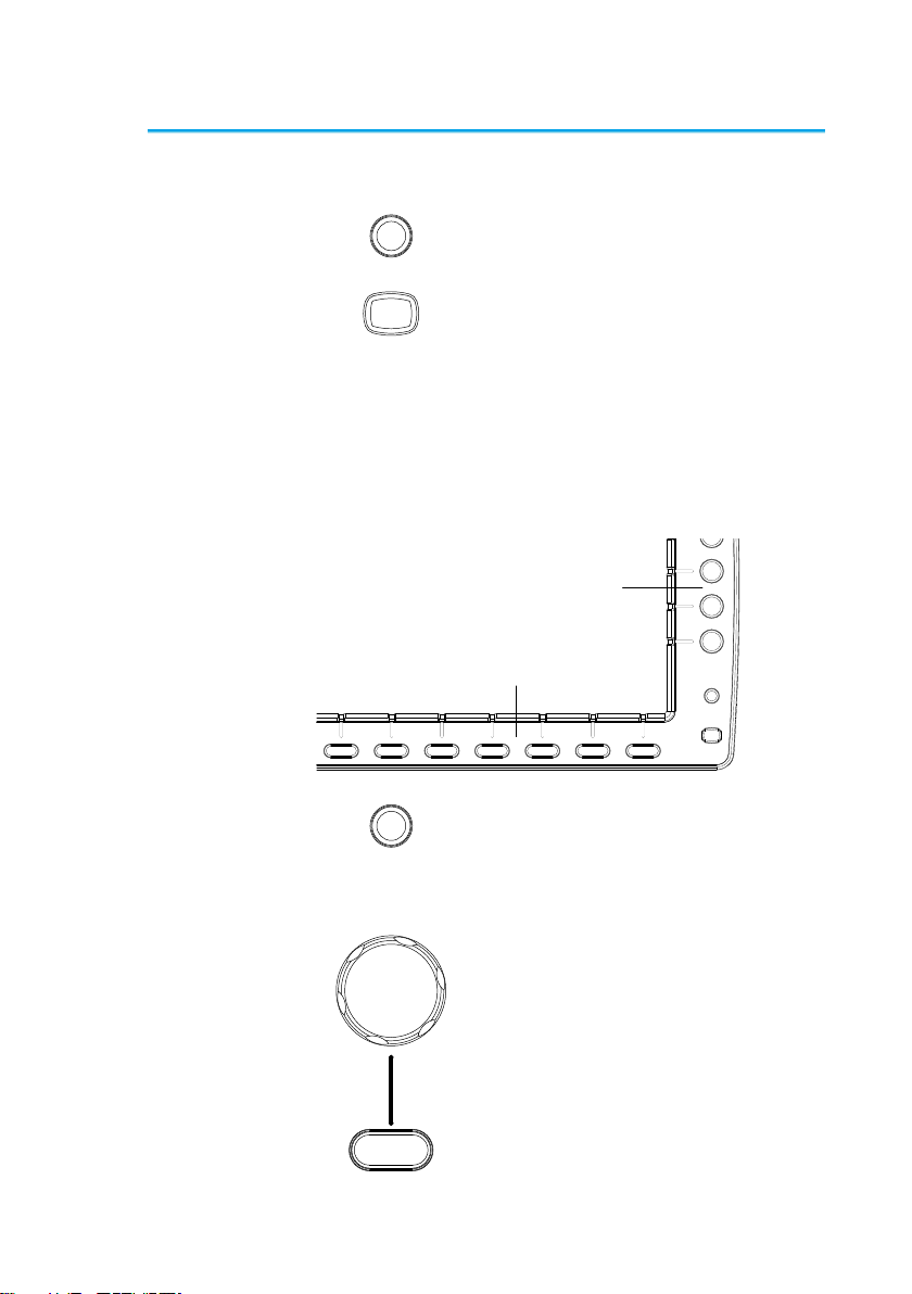
1-3-1. Front Panel
4ch Model
POWER
CH1 CH2
POSITION TIME/DIV
POSITIONPOSITION
VOLTS/DIV VOLTS/DIV
Autoset
Menu
50%
Force-Trig
Select
TRIGGER
HORIZONTAL
VARIABLE
Measure Cursor
Display Help Save/ Recall Utility
Acquire
Single
Run/ Stop
Search
Set/ Clear
CH3 CH 4
POSITION POSITION
VOLTS/ DIV VOLTS/DIV
VERTICAL
M
R
B
Test
CH1 CH2 CH3 CH 4 EXT TRIG
CAT
MW 16pF
300Vpk MAX.
1
CAT
MW 16 pF
300 Vpk MAX.
Hardcopy
Option
Menu Off
LEVEL
Zoom
MATH
REF
Demo
Logic Analyzer
1
BUS
/
GEN 1 GEN 2
Default
LCD
Variable knob
and Select
key
Autoset,Run/Stop,
Single and Default
settings
CH1~CH4
input
Trigger
controls
Function
keys
USB Host port ,
Demo and
Ground terminals
Function
Generator
output 1&2
Power
button
Hardcopy Key
Option
key
Math,
Reference
and Bus
keys
Bottom
menu
keys
Horizontal
controls
Menu key Vertical
controls
Logic
Analyzer
input
EXT
trigger
Side menu keys
2ch Model
CH1 CH2
POSITION TIME/DIV
POSITIONPOSITION
VOLTS/DIV VOLTS/DIV
Autoset
Menu
50%
Force-Trig
Select
TRIGGER
HORIZONTAL
VARIABLE
Measure Cursor
Display Help Save/ Recall Utility
Acquire
Single
Run/ Stop
LEVEL
Search
Set/ Clear
VERTICAL
Test
POWER 2V
Hardcopy
Option
Menu Off
Zoom
CAT
M 16pF
300Vpk MAX.
1
CAT
MW 16 pF
300 Vpk MAX.
1
M
R
B
MATH
REF
BUS
Default
Logic Analyzer
GEN 1 GEN 2 CH1 CH2 EXT TRIG
-2
W
LCD
Variable knob
and Select key Autoset, Run/Stop,Single
And Default Settings
Math,
Reference
and Bus keys
Trigger
controls
Function
keys
USB Host port,
Demo and
Ground terminals
Function
Generator
output 1&2
Power
button
Hardcopy key
Option key
CH1~CH2
input
Bottom
menu
keys
Horizontal
controls
Menu key Vertical
controls
Logic
Analyzer
input
EXT
trigger
Side menu keys
5
LCD Display
8” SVGATFT color LCD. 800 x 600 resolution,
wide angle view display.
Menu Off Key
Menu Off
Use the Menu Off key to hide the
onscreen menu system.
Option Key
Option
The Option key is used to access
any installed options, such the
Logic Analyzer option.
Menu Keys
The Side menu and Bottom menu keys are used to
make selections from the soft-menus on the LCD
user interface.
To choose menu items, use the 7 Bottom menu
keys located on the bottom of the display panel.
To select a variable or option from a menu, use the
Side menu keys on the side of the panel. See page
19 for details.
Hardcopy
Option
Menu Off
Side menu keys
Bottom menu keys
Hardcopy Key
Hardcopy
The Hardcopy key is a quick-save
or quick-print key, depending on its
configuration. For more
information see pages 148(save)
or 148(print).
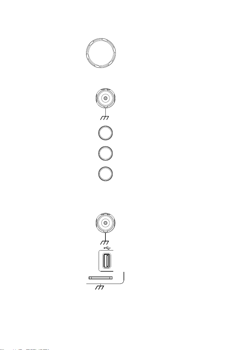
Variable Knob
and Select Key
Select
VARIABLE
The Variable knob is used to
increase/decrease values or to
move between parameters.
The Select key is used to make
selections.

6
Function Keys
The Function keys are used to enter and configure
different functions on the DCS-9700 .
Measure
Measure
Configures and runs automatic
measurements.
Cursor
Cursor
Configures and runs cursor
measurements.
Test
Test
Configures and runs applications.
Acquire
Acquire
Configures the acquisition mode,
including Segmented Memory
acquisition.
Display
Display
Configures the display settings.
Help
Help
Shows the Help menu.
Save/Recall
Save/Recall
Used to save and recall
waveforms, images, panel
settings.
Utility
Utility
Configures the Hardcopy key,
display time, language, calibration
and Demo outputs. It also
accesses the file utilities menu.
Autoset
Autoset
Press the Autoset key to
automatically set the trigger,
horizontal scale and vertical scale.
Run/Stop Key
Run/Stop
Press to Freeze (Stop) or continue
(Run) signal acquisition (page 46).
The run stop key is also used to
run or stop Segmented Memory
acquisition (page 77).
Single
Single
Sets the acquisition mode to single
triggering mode.
Default Setup
Default
Resets the oscilloscope to the
default settings.
Horizontal
Controls
The horizontal controls are used to change the
position of the cursor, set the time base settings,
zoom into the waveforms and search for events*.
Horizontal
Position
POSITION
The Position knob is used to
position the waveforms
horizontally on the display screen.

7
TIME/DIV
Knob
TIME/DIV
The Time/Div knob is used to
change the horizontal scale.
Zoom
Zoom
Press Zoom in combination with
the horizontal Position knob.
Play/Pause
The Play/Pause key allows you to
view each search event in
succession –to effectively “play”
through each search event.
Search
Search
The Search key accesses the
search function menu to set the
search type, source and threshold.
Search Arrows
Use the arrow keys to navigate the
search events.
Set/Clear
Set/Clear
Use the Set/Clear key to set or
clear points of interest when using
the search function.
Trigger Controls
The trigger controls are used to control the trigger
level and options.
Level Knob
LEVEL
Used to set the trigger level.
Trigger Menu
Key
Menu
Used to bring up the trigger menu.
50% Key
50 %
Sets the trigger level to the half
way point (50%).
Force - Trig
Force-Trig
Press to force an immediate
trigger of the waveform.
Vertical
POSITION
POSITION
Sets the vertical position of the
waveform.
Channel Menu
Key
CH1
Press the CH1~4 key to set and
configure the channel.
8
VOLTS/DIV
Knob
VOLTS/DIV
Sets the vertical scale of the
channel.
External Trigger
Input
EXT TRIG
Accepts external trigger signals
(page 95).
Input impedance: 1MΩ
Voltage input: ±15V(peak), EXT
trigger capacitance:16pF.
Math Key
M
MATH
Use the math key to set and
configure math functions.
Reference Key
R
REF
Press the Reference key to set or
remove reference waveforms.
BUS Key
B
BUS
The Bus key is used for parallel
and serial bus (UART, I2C and
SPI) configuration. Serial bus and
parallel bus functionality is
included with the Logic Analyzer
options (DS2-08LA/DS2-16LA).
Channel Inputs
CH1
Accepts input signals.
Input impedance: 1MΩ.
USB Host Port
Demo
TypeA, 1.1/2.0 compatible. Used
for data transfer.
Ground Terminal
Demo
Accepts the DUT ground lead for
common ground.
This manual suits for next models
8
Table of contents
Other TEXIO Test Equipment manuals


