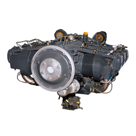
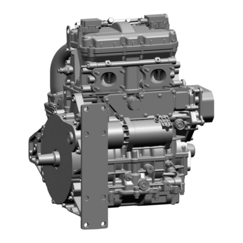
Textron Lycoming O-235 Series User manual

OPERATOR'S
MANUAL
Lycoming
0-235 and 0-290 SERIES
AIRCRAFT ENGINES
4th Edition January 1988
Approved by F.A.A.
Part No. 60297-9

LYCOMING OPERATOR'SMANUAL
ATTENTION
OWNERS, OPERATORS AND
MAINTENANCE PERSONNEL
This operator's manual contains a description of the engine, its
specifications, and detailed information on how to operate and maintain
it. Such maintenance procedures that may be required in conjunction
with periodic inspections are also included. This manual is intended for
use by owners, pilots and maintenance personnel responsible for care of
Avco Lycoming powered aircraft. Modifications and repair procedures
are contained in Avco Lycoming overhaul manuals; maintenance person-
nel should refer to these for such procedures.
SAFETY WARNING
Neglecting to follow the operating instructions and to carry out
periodic maintenance procedures can result in poor engine performance
and power loss. Also, if power and speed limitations specified in this
manual areexceeded, for any reason,damage to the engine and personal
injury can happen. Consult your local FAA approved maintenance facili-
ty.
SERVICE BULLETINS, INSTRUCTIONS AND LETTERS
Although the information contained in this manual is up-to-date at
time of publication, users are urged to keep abreast of later information
through Avco Lycoming Service Bulletins, Instructions and Service Let-
ters whichare available from all Avco Lycoming distributors or from the
factory by subscription. Consult the latest edition of Service Letter No.
L114 for subscription information.
SPECIAL NOTE
The illustrations, pictures and drawings shown in this publication are
typical of the subject matter they portray; in no instance are they to be
interpreted as examples of any specific engine, equipment or part
thereof.

TEXTRON LYCOMING OPERATOR'S MANUAL
IMPORTANT SAFETY NOTICE
Proper service and repair is essential to increase the safe, reliable
operation of all aircraft engines. The service procedures recommended
by Textron Lycoming are effective methods for performing service
operations. Some of these service operations require the use of tools
specially designed for the task. These special tools must be used when
and as recommended.
It is important to note that most Textron Lycoming publications con-
tain various Warnings and Cautions which must be carefully read in
order to minimize the risk of personal injury or the use of improper ser-
vice methods that may damage the engine or render it unsafe.
It is also important to understand that these Warnings and Cautions
are not all inclusive. Textron Lycoming could not possibly know,
evaluate or advise the service trade of all conceivable ways in which ser-
vice might be done or of the possible hazardous consequences that may
be involved. Acordingly, anyone who uses a service procedure must first
satisfy themselves thoroughly that neither their safety nor aircraft safe-
ty will be jeopardized by the service procedure they select.

(LIMITED)
NEWANDREMANUFACTURED
RECIPROCATINGAIRCRAFTENGINE
WHATTEXTRON
LYCOMINGPROMISES
YOU
Textron Lycoming warrants eachnew and remanufactued reciprocating enginesold by it tobe freefromdefects in
material and workmanshipappearingwithin one (1) year from thedate of first operation, excluding necessaryaircraft
acceptance testing Thedate of first operationmust not exceed two (2) years from thedate ofshipment from Textron
Lycoming.
Textron Lycoming'sobligationunder this warrantyshallbe limited to its choiceof repairor replacement, on anex-
changebasis,of theengine orany part ofthe engine,when Textron Lycoming has determined
that theengine isdefective
in materialor workmanship.
Suchrepair or replacementwill be made byTextron Lycoming at no chargeto you.Textron
Lycomig will also bear the cost for labor in connection with the repair or replacement as provided in Textron
Lycoming'sthen current Removaland Installation LaborAllowance Guidebook.
Inaddition,if Textron Lycomingdetermines that the engine proves tobe defectivein material
or workmanshipduring
theperiod until the expirationof Textron Lycoming's recommended Time BetweenOverhaul(TBO), or two(2) years
from thedate of firstoperation,whicheveroccurs first,Textron Lycomingwillreimburseyou fora prorata portionof the
charge for therepair or replacement(atits choice) withTextron Lycoming parts,ofparts requiredtobe repairedorre-
placed, or a replacement engine,if it determines thatengine replacement is required. Textron Lycoming's obligation
during theprorationperiod extends to major parts ofthe engine, whichare limitedto crankcase, crankshaft,camshaft,
cylinders,connectingrods, pistons,sump, accessoryhousingandgears. Theprorationpolicy does not extend to laboror
to accessories,includingbut not limitedto magnetos, caburetors or fuel injectors, fuel pumps,sarers, alternators and
turbochargersandtheircontrollers.
Any engineor part sorepairedor replacedwillbe entitled to warrantyforthe remainderoftheoriginal waranty period.
YOUR
OBLIGATIONS
The enginemust have receivednormal useand service. Youmust applyfor warranty with an authorized Textron
Lycomingdistributorwithin 30days oftheappearance ofthe defect inmaterial orworkmanship.
TextronLycoming's warranty doesnot cover normal maintenanceexpensesor consumable
items.The obligationson
the partof Textron Lycomingset forthabove are yourexclusive remedy and theexclusive liabilityofTextronLycoming.
This warrantyallocates the riskof productfailurebetweenyou and TextronLycoming,as permittedby applicable law.
TextronLycoming reservesthe rightto deny any warrantyclaimif it reasonablydetermines that theengine orpart has
been subject to accident orused, adjusted,altered, handled,maintainedorstored other thanasdirected in youroperator's
manual, or if non-genuine TextronLycoming parts are installedin or onthe engineand aredetermined tobeapossible
causeof theincident for whichthe warrantyapplicationis filed.
TextronLycoming maychangethe constructionofenginesat any time withoutincurring
any obligationto incorporate
suchalterations in enginesorparts previouslysold.

THIS LIMITED WARRANTYIS EXCLUSIVEAND INLIEU
OF ALL.OTHERWARRANTIESANDREPRESEN-
TATIONS,EXPRESSOR IMPLIED ORSTATUTORY,
WHETHERWRITTEN ORORAL, INCLUDING
BUTNOT
LIMITED TOANY WARRANTYOF MERCHANTABILITY
OR FITNESS FORANY PARTICULAR
PURPOSE,
ANDANY IMPLIED WARRANTY ARISING FROM ANY COURSE OF PERFORMANCEOR DEALING OR
TRADEUSAGE.THIS WARRANTYIS ALSO IN LIEUOF ANYOTHER
OBLIGATION, LIABILITY,RIGHT OR
CLAIM, WHETHER IN CONTRACT OR IN TORT, INCLUDING ANY RIGHT IN STRICT LIABILITY IN
TORT OR ANY RIGHT ARISINGFROM NEGLIGENCE ON THE PART OF TEXTRON LYCOMING,AND
TEXTRON LYCOMING'S LIABILITY ON SUCHCLAIMSHALL NNO CASE EXCEED THE PRICE ALLO-
CABLETOTHE ENGINEORPARTWHICHGIVESRISE
TOTHE CLAIM.
LIMITATION
OF LIABILITY
IN NOEVENT,WHETHER AS ARESULTOF ABREACHOFWARRANTY,CONTRACT OR ALLEGEDNEG-
LIGENCE,SHALLTEXTRON LYCOMINGBE LIABLEFORSPECIALOR CONSEQUENTIAL
OR ANYOTHER
DAMAGES, INCLUDINGBUTNOT LIMITED TOLOSSOF PROFITSOR REVENUES, LOSS OF USE OFTHE
ENGINEORCOSTOF A REPLACEMENT.
No agreement varying this warranty orTextron Lycoming's obligations under it will be binding upon Textron
Lycomingunlessin writingsignedbya dulyauthorizedrepresentativeofTextron Lycoming.
Effective October1, 1995 Revision "J'
Textron Lycoming
Williamsport, Pennsylvania

WARRANTY
(LIMITED)
REPLACEMENT
PART - RECIPROCATING
AIRCRAFT
ENGINE
WHATTEXTRON
LYCOMING
PROMISES
YOU
Textron Lycoming
warrants each new reciprocatingaircraftengine replacementpat soldbyit to be freefrom defects
inmaterial and workmanshipappearing within one (I) year from its date of firstoperation. The date of firstopera-
tion. must not exceed two(2) years from thedateof shipmentfrom Textron Lycoming.
Textron Lycoming's obligation
under this
warranty shallbe limited to its choiceof repairorreplacement, on an ex-
changebasis, of te replacement part, when TextronLycoming has determined thatthepan isdefective inmaterial or
workmanship.TextronLycoming will also reimburse youforthe costs forlaborin connectionwith therepair or replace-
mentas providedin Textron Lycoming's thencurrent Removal
and Installation
Labor AllowanceGuidebook
Any part so repaired
orreplacedwill be warranted forthe remainder
of theoriginal warrantyperiod.
YOUR
OBLIGATIONS
The enginein which
the replacementpartisinstalledmust have receivednormal use and service. Youmust applyfor
warrantywith an authorized
Textron Lycoming distributorwithin 30days of the appearanceof thedefect in materialor
workmanship.
TextronLycoming's warranty does not cover normal maintenance
expenses orconsumable
items. Theobligations
on
the part ofTextron Lycoming setforth aboveare yourexclusive
remedyand theexclusive liabilityofTextronLycoming.
This warrantyallocates the riskof productfailure between you andTextronLycoming,aspermitted byapplicable law.
Textron Lycoming reserves theright to deny
any warrantyclaim if itreasonablydeterminesthattheengineor part has
been subjectto accident or used,adjusted,altered, handled,minained or storedother thanas directed in youroperator's
manual, or if non-genuine Textron Lycoming partsare installedin or on theengine and aredetermined tobe a possible
cause ofthe incidentforwhich thewarrantyapplication is filed.
Textron Lycoming may changetheconstructionof engines atany time withoutincurring anyobligation to incorporate
such alterations
in enginesor pars previouslysold.
THIS LIMITED WARRANTY
ISEXCLUSIVEAND INLIEU OF
ALL OTHER
WARRANTIES AND
REPRESEN-
TATIONS,EXPRESS ORIMPLIED ORSTATUTORY,
WHETHERWRITTEN OR ORAL, INCLUDINGBUTNOT
LIMITED TO ANY WARRANTY
OF MERCHANTABILITY OR FITNESS FOR ANY PARTICULAR PURPOSE,
ANDANY IMPLIED WARRANTY ARISING FROM ANY COURSE OF PERFORMANCE OR DEALING OR
TRADEUSAGE.THIS WARRANTY
IS ALSO INLIEU OF ANYOTHER
OBLIGATION, LIABILITY,
RIGHT OR
CLAIM, WHETHER IN CONTRACT OR IN TORT, INCLUDING ANY RIGHT IN STRICT LIABILITY IN
TORT OR ANY RIGHT ARISING FROM NEGLIGENCE ON THE PART OF TEXTRON LYCOMING, AND
TEXTRON LYCOMING'S LIABILITY ON SUCH CLAIMSHALL INNO CASE EXCEED THE PRICE ALLO-
CABLE TOTHE ENGINEOR PARTWHICHGIVES RISETOTHE CLAIM.

LIMITATION
OF
LIABILITY
IN NO
EVENT, WHETHER AS ARESULT
OFA BREACHOFWARRANTY, CONTRACTOR ALLEGED
NEG-
LIGENCE,SHALL
TEXTRONLYCOMING BELIABLEFOR
SPECIALOR CONSEQUENTIAL
ORANY OTHER
DAMAGES,INCLUDINGBUT NOT LIMITED TOLOSS
OF PROFTS OR REVENUES, LOSS
OF USE OFTHE
ENGINE
ORCOST OFA REPLACEMENT.
No agreement varying this warranty or Textron Lycoming's obligations under it will be binding upon Textron
Lycoming
unlessin writing signed
bya duly authorizedrepresentative
of
Textron Lycoming.
Effective October 1,1995 Revision "J"
TextronLycoming
Williamsport,Pennsylvania

I.Lycoming
WARRANTY
(LIMITED)
OVERHAULED
RECIPROCATING AIRCRAFT ENGINE
WHAT TEXTRON LYCOMINGPROMISES YOU
Textron Lycoming warrants
each overhauled
reciprocating enginesold
by it tobe freefrom defects
in materialand
workmanshipappearing withinone (1) year from thedate of first
operation, excluding necessary aircraft acceptance
testing. The dateof first operationmust not exceedtwo (2) years fromthedateof shipmentfromTextron Lycoming.
Textron Lycoming'sobligationunder thi:;warrantyshall be limited toits choice of repairor replacement, on an ex-
changebasis, oftheengineor anypart of the engine,whenTextron Lycoming
hasdetermined
thatthe engineis defective
in materialor workrmanship.Suchrepair
or replacementwillbe made by TextronLycoming
at nochargeto you.Textron
Lycoming will also bear the cost for labor in connection with the repair or replacement as provided in Textron
Lycoming'sthencurrent Removaland
InstallationLaborAllowanceGuidebook.
Anyengine orpartso repaired
orreplacedwillbe entitledto warrantyfortheremainderof theoriginal warranty
period.
YOUR OBLIGATIONS
The engine
must have receivednormal use and service. Youmust applyfor warranty with an authorized Textron
Lycomingdistributor
within30 daysof theappearance
of thedefect
in material
orworkmanship.
Textron Lycoming's
warranty doesnot cover nominal
maintenanceexpensesorconsumable
items.Theobligationson
the pan ofTextron Lycomingsetforth abovt areyourexclusive remedyand theexclusive liabilityofTextron Lycoming.
This warrantyallocatesthe risk ofproductfailurebetween youand TextronLycoming,
aspermittedby applicablelaw.
TextronLycoming reserves
theright todeny any
warrantyclaimif it reasonably
determinesthat theengine orparthas
been subjecttoaccident orused, adjusted,altered,handled,maintained
orstoredother thanas directedin youroperator's
manual, orif non-genuine TextronLycoming partsare installedin oron theengine and aredetermined tobe a possible
causeof the incidentfor which
the warrantyrpplication
is filed.
TextronLycoming may change theconstruction
ofenginesat any timewithoutincurring
any obligation
to incorporate
suchalterations inenginesorparts previouslysold.
THIS LIMITED WARRANTYISEXCLUSIVEAND IN LIEUOF ALL OTHER
WARRANTIESAND REPRESEN-
TATIONS,EXPRESS
ORIMPLIED ORSTATUTORY,
WHETHER
WRITTEN OR ORAL, INCLUDINGBUT
NOT <
LIMITED TOANY WARRANTYOF MERCHANTABILITY
OR FITNESS FOR ANY PARTICULARPURPOSE, <
ANDANY IMPLIEDWARRANTY ARISING FROM ANYCOURSE OF PERFORMANCEOR DEALING OR
TRADE
USAGE.THISWARRANTY
IS ALSO INLIEU OFANY OTHEROBLIGATION, LIABILITY,
RIGHT OR
CLAIM, WHETHER IN CONTRACT O IN TORT, INCLUDINGANY RIGHT IN STRICT LIABILITY IN
TORT OR ANY RIGHT ARISING FROM NEGLIGENCEON THE PART OF TEXTRON LYCOMING, AND
TEXTRON LYCOMING'S LIABILITY ON SUCH CLAIMSHALL INNO CASE EXCEED THE PRICEALLO-
CABLE TOTHE ENGINEORPARTWHICHGIVES
RISETO THECLAIM.
LIMITATION
OF
LIABILITY
IN NO EVENT, WHETHER AS
A RESULT
OF
A BREACH
OF WARRANTY, CONTRACTOR ALLEGED
NEG-
LIGENCE,SHALLTEXTRON
LYCOMING BELIABLEFOR
SPECIALOR CONSEQUENTIAL
ORANY OTHER
DAMAGES, INCLUDING BUT
NOT LIMITED TOLOSS
OF PROFITS
OR REVENUES, LOSS
OF USE OF
THE
ENGINEORCOST OF
A REPLACEMENT.
No agreement varying this warranty or Textron Lycoming's obligations under it will be binding upon Textron
Lycoming
unlessin writing signed
bya duly authorizedrepresentative
ofTextron Lycoming.
Effective October 1, 1995 Revision J"
TextronLycoming
Williamsport, Pennsylvania
I
i
i

5.
314 Right Fmnt View - 0-235-C, 0-290-D

Rear View - O-290-D2

LYCOMING
OPERATOR'S
MANUAL
DESCRIPTION
Page
General ................................................ 1-1
Cylinders .............................................. 1-1
Valve Operating Mechanism ............................. 1-1
Crankshaft ............................................ 1-2
Crankcase ............................................. 1-2
Oil Sum p .............................................. 1-2
Connecting Rods ...................................... 1-2
Pisto ns . ... .. .... .. ... ... . ... .. .. .. . .... .. .. .... ... .... 1-2
Accessory Housing ..................................... 1-2
Gears ................................................. 1-2
Cooling System ........................................ 1-3
Lubricating System ..................................... 1-3
Induction System ....................................... 1-3
Ignition System ........................................ 1-3
Table of Models ........................................ 1-4

LYCOMING
OPERATOR'S
MANUAL
0-235AND 0-290SERIES SECTION 1
SECTION 1
DESCRIPTION
The Lycoming 0-235 series, 0-290-Dseries and 0-290-D2series
engines are four cylinder, direct drive, horizontally opposed, wet sump,
air-cooled models.
In referring to the location of the various engine components,the parts
are described in their relationship to the engine as installed in conven-
tional airframes. Thus the power take-off end is considered the front and
the accessory drive section the rear. The sump section is considered the
bottom and the opposite side of the engine where the shroud tubes are
located is the top. References to the left and right side of the engine are
made with the observer facing the rear of the engine. Thus the front
cylinder on the left bank is number 2 and the rear cylinder is number 4.
The front cylinder on the right bank is number 1 and the rear cylinder is
number 3.The direction ofrotation for accessory drives is determined by
the observer facing the drive pad. The direction of rotation of the
crankshaft, viewed from the accessory end of the engine is clockwise.
Cylinders -The cylinders are of conventional air-cooled construction
with the two major parts, head and barrel, screwed and shrunk together.
The heads are made from an aluminum alloy casting with a fully machin-
ed combustion chamber. The barrels, which are machined from chrome
nickel molybdenum steel forgings with deep integral cooling fins, are
ground and honed to a specified finish.
The valve rocker shaft bearing supports and the rocker box housing
are cast integrally with the head. The valves are cooledby means of fins
which completely surround the area ofthe exhaust valve and portions of
the intake valves, Valve guides and valve seats are shrunk into machin-
ed recesses in the head.
Valve Operating Mechanism -The valve operating mechanism is located
on the top side. The camshaft is located parallel to and above the
crankshaft and operates in aluminum bearings. The camshaft in turn ac-
tuates the valves by means oftappets. The valve rockers are supported
on full floating, steel shafts. The valve springs bear against hardened
steel seats.
1-1

LYCOMING OPERATOR'SMANUAL
SECTION 1 0-235AND 0-290
SERIES
NOTE
Hydraulic tappets which automatically keep the valve clearanceat zero
are employed on the 0-290-D2series engines while solid tappets are
employed on the 0-235
and 0-290D series. Proper valve clearanceon the
latter models is maintained by means of an adjusting screw located in
the valve rocker.
Crankshaft -Made from a chrome nickel molybdenum steel forging. All
bearing surfaces are nitride hardened. The expansion plug in the
crankshaft must be removed on those models employing a two position
hydro control or variable pitch propeller.
Crankcase - Crankcase assembly consists of two reinforced aluminum
alloy castings divided at the center line of the engine and fastened
together by bolts and nuts. The mating surfaces of the crankcase are
joined without the use of a gasket, and main bearing bores are machined
for use of precision type main bearing inserts.
OilSump -Incorporates an oil suction screen, carburetor mounting pad,
the intake riser and intake pipe connections. The fuel-air mixture, as it
passes through the riser, is vaporized by the heated oil that surrounds
the riser.
Connecting Rods - Made in the form of "H" sections from alloy steel
forgings. They have replaceable bearing inserts in the crankshaft ends
and split type bronze bushings in the piston ends. The bearing caps on
the crankshaft ends are retained by means of two bolts and nuts through
each cap.
Piston -Machined from an aluminum alloy. Twocompression rings and
an oil regulating ring are employed on all pistons. In addition, the 0-235
series employs an oil scraper ring below the piston pin. The piston pin is
ofthe full floating type with a plug located at each end to prevent the pin
from touching the cylinder wall.
Accessory Housing -Made from an aluminum casting and is fastened to
the rear of the crankcase and the top rear of the oil sump. It forms a
housing for the oil pump and the various accessory drives.
Gears - Are of the conventional type and precision machined, hardened
to insure long life and satisfactory operating qualities.

LYCOMING OPERATOR'S MANUAL
0-235AND0-290SERIES SECTION 1
CoolingSystem -These engines are designed to becooled by air pressure
actuated by the forward speed of the aircraft. Close fitting baffles build
up a pressure and force the air through the cylinder fins. The air is then
exhausted through gills or augmentor tubes usually located at the rear
of the cowling.
Lubrication System -The full pressure wet sump lubrication system is
actuated by an impeller type oil pump contained within the accessory
housing.
Induction System - These engines are equipped with either of two
Marvel-Schebler carburetors, MA-3A or MA-3SPA. See Table 1 for
model application. Both carburetors are of the single barrel float type
and are equipped with manual mixture control and "idle cut-off". Par-
ticularly good distribution of the fuel-air mixture to each cylinder is ob-
tained from the center zone induction system, which is integral with the
sump and is submerged in oil, insuring a more uniform vaporization of
fuel and aiding in cooling the oil in the sump. From the riser the fuel-air
mixture is distributed to each cylinder by individual intake pipes.
Ignition System -Dual ignition is furnished by two magnetos. Consult
Table 1 for proper model application. Depending on installation the igni-
tion wiring is so arranged as shown in either figure 5-1, 5-2or 5-3.

LYCOMINGOPERATOR'S
MANUAL
TABLE 1
MODELAPPLICATION
Model
0-235-C
0-235-C,-E1,
-F1,-G1
0-235-C1B,-E1B,
-F1B,-G1B
0-235-C2A,-E2A,-F2A,
-G2A,-K2A,-J2A
0-235-L2A*,-N2A*,-P2A*
0-235-M1*
0-235-C2B,-E2B,-F2B,
-G2B,-K2B,-J2B
0-235-C2C,-H2C
0-235-K2C
0-235-L2C, -N2C**
0-290-D
0-290-D2
0-290-D2A
0-290-D2B
0-290-D2C
Magneto
Left Right
S4LN-21 S4LN-20
S4LN-21 S4LN-20
S4LN-200 S4LN-204
S4LN-21 S4LN-20
S4LN-21 S4LN-20
or
S4LN-204
S4LN-21 S4LN-20
or
S4LN-204
Propeller
Carburetor Flange
Specification
(Modified)
MA-3A or -3PA AS-127-2
MA-3A or -3PA AS-127-1
S4LN-1227
4251
4252
4252
or
4281
S4LN-21
S4LN-21
S4LN-21
S4LN-21
S4LN-200
S4LN-1209
4250
4250
or
4252
4250
or
4281
S4LN-20
S4LN-20
S4LN-20
S4LN-20
S4LN-204
MA3A-3PA
MA-3A or -3PA
MA-3A or -3PA
MA-3A or -3PA
MA3A or -3PA
MA-3SPA
MA-3SPA
MA-3SPA
MA-3SPA
MA-3SPA
AS-127-2
AS-127-1
AS-127-1
AS-127-1
AS-127-1
AS-127-2
AS-127-2
AS-127-2
AS-127-2
AS-127-2
* 0-235-L2A, -M1, -N2A, -P2A may have two (2) S4LN-21 magnetos as
optional equipment.
** 0-235-L2C, -N2C may have two (2) 4252 magnetos as optional equipment.
1-4

LYCOMING OPERATOR'SMANUAL
SPECIFICATIONS
Page
Specifications -0-235 ................................... 2-1
Specifications - 0-290 ................................... 2-2
Accessory Drives ...................................... 2-2
Alternate Power Ratings ..... .......................... 2-3
Detail Weights ........................................ 2-4

LYCOMING OPERATOR'S
MANUAL
SECTION2 0-235AND 0-290SERIES
SPECIFICATIONS
0-235SERIES
*-C-E -C1C -F-G-J -N-P
FAA Type Certificate 223 223
Take-off horsepower 115 115
Take-off RPM 2800 2800
Rated horsepower 115 108
Rated RPM 2800 2600
Bore, inches 4.375 4.375
Stroke, inches 3.875 3.875
Displacement, cu. in. 233.3 233.3
Compression ratio 6.50:1 6.75:1
Prop. drive ratio 1:1 1:1
Prop. driven rotation
(viewedfrom rear) Clockwise Clockwise
Firing orders 1-3-2-4 1-3-2-4
Spark occurs, BTC 25 25
Rocker clearance, cold .007/.009 .007/.009
* -0-235-C1
has provision for two position prop.
223
125
2800
125
2800
4.375
3.875
233.3
9.7:1
1:1
223
116
2800
116
2550
4.375
3.875
233.3
8.1:1
1:1
Clockwise Clockwise
1-3-2-4 1-3-2-4
25 20
.007/.009 .007/.009
control valve.
FAA Type Certificate
Take-off horsepower
Take-off RPM
Rated horsepower
Rated RPM
Bore, inches
Stroke, inches
Displacement, cu. in.
Compression ratio
Prop. drive ratio
Prop. drive rotation
(viewedfrom rear)
Firing orders
Spark occurs, BTC
Rocker clearance.
cold
-K-L-M
223
118
2800
118
2800
4.375
3.875
233.3
8.5:1
1:1
Clockwise
1-3-2-4
20
-H -K2C
223
115
2800
108
2600
4.375
3.875
233.3
6.75:1
1:1
Clockwise
1-3-2-4
25
223
118
2800
115
2700
4.375
3.875
233.3
8.5:1
1:1
Clockwise
1-3-2-4
20
.007/.009 .007/.009 .007/.009
NOTE
Engine models are categorized according to their basic series. Any
model that varies in specification within a series is listed separately.
Spark advance is also found on name plate.
2-1

LYCOMING OPERATOR'SMANUAL
0-235
AND0-290
SERIES SECTION 2
SPECIFICATIONS
0-290SERIES
-D2,
-D2A -D2B,
-D2C
FAA Type Certificate
Take-off horsepower
Take-off RPM
Rated horsepower
Rated RPM
Bore, inches
Stroke, inches
Displacement, cubic in.
Compression ratio
Propeller drive ratio
Propeller driven rotation
(viewedfrom rear)
Firing order
Spark occurs, BTC
Valve rocker clearance
(hyd. tappets collapsed)
Valve rocker clearance
(cold)
Accessory Drive
Starter
Generator
Generator (Optional)
Alternator
Vacuum Pump
Hydraulic Pump
Tachometer
Magneto
Fuel Pump
Prop. Governor
AN Drive
* - Facing Drive Pad.
229
130
2800
125
2600
4.875
3.875
289.0
6.50:1
1:1
Clockwise
1-3-2-4
25
229
140
2800
135
2600
4.875
3.875
289.0
7.50:1
1:1
Clockwise
1-3-2-4
18
229
140
2800
135
2600
4.875
3.875
289.0
7.00:1
1:1
Clockwise
1-3-2-4
25
.028-.080 .028-.080
.007/.009
Drive Ratio *Direction of Rotation
13.556:1
1.910:1
2.500:1
3.250:1
1.300:1
1.300:1
0.500:1
1.000:1
0.500:1
0.866:1
1.000:1
Counter-Clockwise
Clockwise
Clockwise
Clockwise
Counter-Clockwise
Counter-Clockwise
Clockwise
Clockwise
Plunger Operated
Clockwise
Counter-Clockwise
2-2
This manual suits for next models
1
Table of contents
Other Textron Engine manuals

Textron
Textron Cessna MK206-34-09 User manual

Textron
Textron Lycoming O-235-C User manual

Textron
Textron Lycoming IO-540 Series User manual

Textron
Textron LYCOMING O-320 Series User manual

Textron
Textron MPE 850 MARINE User manual

Textron
Textron MPE 850 OFF-ROAD User manual

Textron
Textron Lycoming IO-360 User manual

Textron
Textron MPE 850 OFF-ROAD Operating instructions