Textron Ezgo RXV-E User manual

Customer Care
RXV-E Advanced Trouble-Shooting
Guide
610873

Customer Care
Table of Contents
Safety 1
Hand Held Diagnostic Tool 2
Special Tool List 3
Wiring Diagrams4-6
Symptoms 7
Error Codes 8
8976 AC Over Current 9
9024 AC Short Circuit 10
12576 DC Bus Timeout 11-12
12817 DC Bus High – Software Detected 13-14
12818 DC Bus High – Hardware Detected 15-16
12833 DC Bus Low 17-19
16912 Motor temp High 20
17168 Heat Sink Temp High 21
20753 15V Supply Low Voltage 22
20755 5V Supply Low or High Voltage 23-25
21008 Current Sensor Offset Calibration 26
21520 Open Drain Output Current High 27-28
33024 CAN Time Out 29
25104 Direction Error 30
25105 Throttle Sensor Error 31
25106 Reverse Alarm Test Failed 32
25107 Mechanical Brake Test Failed 33-34
25108 Brake Sensor Error 35
Additional Component Testing 36-38
Warnings 39
Page

Customer Care
Vehicle Operation
Understanding the Power-up Sequence
• The car will perform the following checks during the first
second of initial key – on.
• Electric brake check – Controller tries to rotate the motor
¼ turn in both directions.
• Park brake check – Controller disengages and reengages
the park brake.
• Reverse alarm check – Controller sounds the alarm for
100ms.
• Charger inhibit check – Controller checks the charge
receptacle for connection to the charger.
• Throttle switch check – Throttle switch must be open to
pass the start up test.
• Throttle position sensor – Controller checks the TPS for 0%
throttle. .38-.56 volt
• Throttle operation check – Controller checks the TPS for the
correct open and closed range. .5-4.8v
The car will not run if the controller detects a problem
with any of the circuits above.

Customer Care
Safety
Always wear personal protective equipment
Wrap battery wrenches to prevent accidental
connection.
Use a 2X4X12” to spread the load between the jack pad and the composite bumper!
Always properly lift the vehicle
and chock the wheels to prevent
accidental drive away.
Page 1

Customer Care
Hand Held Diagnostic Tool
Using The Hand Held Tool
•Turn the key switch off.
•Insert the diagnostic tool plug into the
CAN port under the cup holder / console.
•Turn the key on.
•The diagnostic tool screen will
illuminate.
•The #1 & #5 arrows control upward and
downward movement of the cursor.
•The #4 button breaks down each menu
item to a sub-menu
•The #5 button returns the user to the
previous screen.
•The #3 button is used to enter / reset
selections.
The three primary functions used for
electric trouble-shooting are:
•Diagnostic Report
•Errors
•Warnings
Page 2
The Hand Held diagnostic
Unit is required for all
testing and warranty
reporting!

Customer Care
Tools
The following tools will be required to perform advanced trouble shooting procedures:
1. Handheld diagnostic tool PN# 606215
2. Digital volt ohm meter (DVOM)
3. Wire insulation piercing tools 3A. Grainger PN# 1RK18 or 3B. Radio Shack
PN# 270-334B or equivalent.
4. Alligator adapter clamps for meter leads Radio Shack PN#270-354 or equivalent.
1
2
3A.
3B.
4
Page 3

Customer Care
Page 4
Controller 23 pin connector pin listing with voltages
Pin 1- 48 volt input when key switch is in any position other than off. (FWD, N, REV)
Pin 2- 48v switched ground output for electric motor brake.
Pin 3- 5v positive output for sensor circuit.
Pin 4- 5v ground output for sensor circuit.
Pin 5- 5v signal input from the motor encoder. 0-5 volt variable
Pin 6- 5v signal input from the motor encoder. 0-5 volt variable
Pin 7- 5v signal input from the brake sensor. 0-.35v is a fault, .36-3.78 is linear braking, 3.78-4.8
is 100% braking, >4.8v is a fault.
Pin 8- 48v can ground, internal 48v ground.
Pin 9- 5v signal input for the accelerator sensor. 0-.35v is a fault, .36-.56 is 0% throttle, .5-4.1v is
acceleration range, 4.1-4.8 is 100% throttle, >4.8v is a fault.
Pin 10- 48v ground output from controller for the reverse buzzer. active in reverse and during start
up only.
Pin 11- 5v signal wire output for SOC meter. .5v at empty, 4.5v at full reading.
Pin 12- 48v positive input from key switch for forward.
Pin 13- 48v input for run/tow switch.
Pin 14- 48v positive input for resistor circuit.
Pin 15- Output CAN low.
Pin 16- 5v positive for motor temp sensor.
Pin 17- 48v positive input for charger interlock. 0v with charger plugged in. 21-28v with charger
unplugged.
Pin 18- 48v output ground circuit for the solenoid.
Pin 19- 48v positive input from accelerator switch.
Pin 20- 48v input from key switch for reverse.
Pin 21- 48v ground for the resistor control circuit.
Pin 22- 15v output for the brake light circuit.
Pin 23- Can buss high for hand held.

CBA
D
C
BA
AB
3
21
4
5
6
987
B
A
2
9
35678
15
1
13
1211
10
16 17 18 19 20 21 22 23
E
DC
B
A
F
AB
CBA
ABCD
A
B
C
BA
C
B
A
C
B
A
CBA
RED
RED
RED
RED
RED
RED
BLK
BLK BLK
RED/WHT
BLK/WHT
BLK/WHT
RED
RED
RED
RED
RED
RED
WHT
LT.BLUE
LT.BLUE
RED
RED
WHT
GRN
RED PINK
ORG
BLU/WHT
BLK
RED
ORG
YEL
YEL
YEL
YEL
YEL
LT.GRN
BLK
BLK
BLK
BLK
RED
RED
GRAY
PURPLE
ORG/RED
RED
BLK/WHT
WHT
BLK
GRN/BLK
BLK
BLK
GRAY
BLK
BLK
ORG
ORG
THW/ELPRUP
RESISTOR
CONTROL
BI-METAL
SWITCH
SOLENOID
COIL TEMP
SENSOR
MOTOR
SENSOR
B-
BATTERY
BRK (-)
BRK (+)
BRAKE
BRAKE
LIGHTS
REVERSE
BUZZER
TOW
SWITCH
CHARGER
RECEPTACLE
SOC
METER
THROTTLE
SWITCH
B+
SOLENOID
THROTTLE
SENSOR
BRAKE
SENSOR KEY SWITCH
INLINE
FUSE #1
POWER
BRAKE
LIGHT
RELAY
BRAKE
SWITCH
RESISTOR
INLINE
FUSE #2
B+
BATTERY
BLK/WHT
LT GREEN
ORG/RED
RED/WHT
PURPLE
GRAY
GRAY
BLK
BLK
BLK BLK
BLK
GRN
BLUE/WHT
WHT
ORG
PNK
YEL
RED
LT . BLUE
LT . BLUE
WHT PURPLE/WHT
12
9
35678
5
3
1211
10
6789 20 21 22 23
3
21
4
5
6
98
7
BLK/WHT
BLK/WHT
RED/WHT
ORG/RED
RED
RED
RED
BLK
BLK
CAN
INTERFACE
FRONT VIEW
OF CONNECTOR
B
A
CN
8
4
2
456
9
8
7
RED
GRN/BLK
RUN
PLUG
FRONT VIEW
OF CONNECTOR
Customer Care
RXV – E Wiring Diagram
Page 5

Customer Care
RXV – E Wiring Diagram
Page 6

Customer Care
Symptoms
Crawling: Vehicle runs extremely slow. Slower than limp home. Check motor encoder. See
pages 24 - 25
Rapid solenoid engage – disengage: Occurs when the key is on and the charger is
plugged in. Check key switch and charger receptacle for failed interlock. See pages 30 & 36
Motor shuttering: Check for loose connections on the V,U,&W. Check encoder
connections and park brake harness connections. Verify throttle sensor. Inspect for dragging
park brake. Compare command speed with actual speed on the hand held. RPM should
almost be the same. If not suspect the motor or a mechanical blockage. Compare DC amp
draw and AC current. AC current should be around 50% lower than DC. If not, suspect
motor or mechanical blockage. See pages 9,10,23,24, 25,33, & 34
Metallic Motor noise: Inspect for dragging park brake or failed motor bearing.
See pages 33 & 34.
No park brake disengage even in tow position: Verify power to the park brake, solenoid,
tow switch, or the brake coil driver. See pages 17,18,33 & 34
Roll freely in the run position then lock after a few feet: Verify brake coil driver and
alignment. See pages 33 & 34
Excessively loud reverse alarm: Check for DC Bus High. See pages 13 - 16
Excessively soft reverse alarm: Check for DC Bus Low or a failed reverse buzzer. See
pages 17,18 & 32
Car goes into limp home mode: Check for DC Bus Low. See pages 17 - 19
Solenoid engages once then disengages: Happens as a result of damage in 5V circuit.
Verify brake & throttle sensors, motor encoder, SOC meter, controller. See pages 23 -25
Charger does not turn on: Verify charge receptacle, DC cord, AC power or charger.
Vehicle does not run or engage solenoid: Check the fuse, charge receptacle, and key
switch. See pages 30 & 36
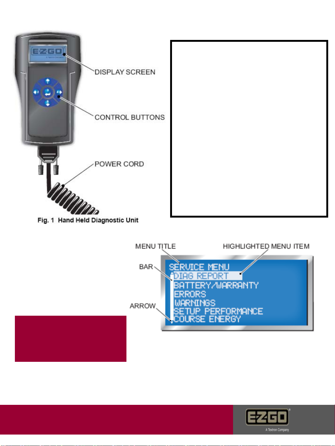
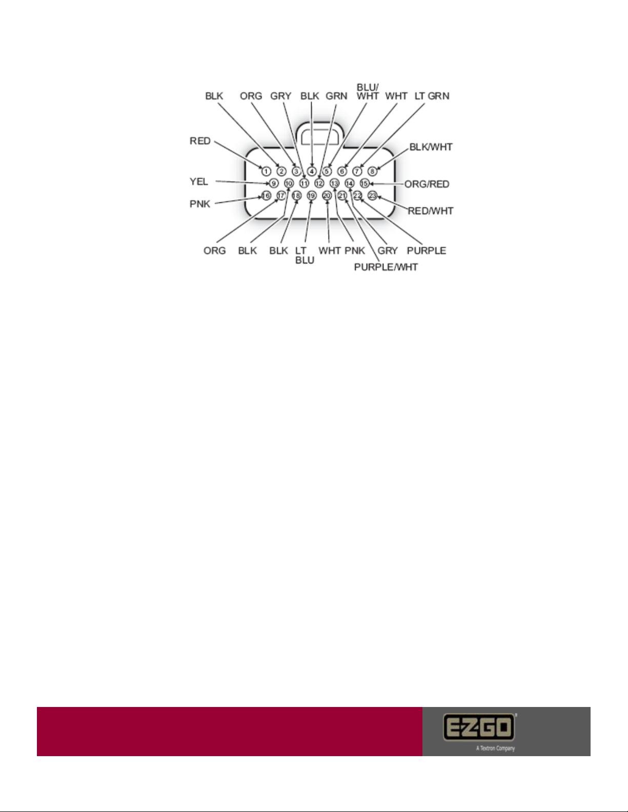
Vehicle does not run and the hand held tool will not turn on – Verify key switch voltage
and can plug connections. See page 29 & 30
Page 7

Customer Care
Error Codes
Notes:
•If the car is experiencing an error at the time of diagnostics, the error can
be viewed on the error status screen.
•If the car is not currently experiencing the error, but has in the past; the
error can be viewed in the error log screen.
•If the failure is electrical in nature, an error will appear in the status or log
screen.
•If the fault is mechanical in nature or a design function of the vehicle; an
error code may not be observed on either screen.
Error codes can be accessed using the
diagnostic hand held tool. Scroll down to
the error code screen then press the 4
key to view sub menu codes.
Error status will show current active faults.
Example codes: Shown are examples of
error codes stored in the error log. The
log can hold up to 7 entries. Errors will
remain in the log after a repair has been
made. LTIME represents when a fault
occurred in vehicle life time minutes which
is listed as CPU time n the battery status
screen. LTime is the last time this error occured.
Only the Ltime will update if the code is already
listed on this screen.
Page 8

Customer Care
8976 AC Over Current
Caused By: Software detects motor current 50% higher than controller
peak rated current.
5. Try a known good controller if error is
gone, warranty controller. Error remains,
reinstall controller and contact Customer
Care.
1. Turn key off and back on
to reset the controller. If car
runs, return to service. If
not, proceed to remaining
steps.
2. Disconnect all three motor wires.
Contact the V wire lug to the pos. meter
terminal A. Contact the U lug to the
negative terminal B. Meter ohm resistance
should be 0.0 – 0.2. If not, replace motor.
3. Contact the V wire lug to the pos. meter
terminal A. Contact the W lug to the
negative terminal B. Meter ohm resistance
should be 0.0 – 0.2. If not, replace motor.
4. Contact the U wire lug to the pos. meter
terminal A. Contact the W lug to the
negative terminal B. Meter ohm resistance
should be 0.0 – 0.2. If not, replace motor.
A
B
A
B
B
A
Page 9

Customer Care
9024 AC Short Circuit
Caused by: Short circuit detected in controller, motor cables, motor, or failed solenoid.
1. Turn key off and back on
to reset the controller. If car
runs, return to service. If
not, proceed to remaining
steps.
2. Disconnect all three motor wires.
Contact the V wire lug to the pos. meter
terminal. Contact the U lug to the
negative terminal. Meter ohm resistance
should be 0.0 – 0.2. If not, replace motor.
3. Contact the V wire lug to the pos.
meter terminal. Contact the W lug to the
negative terminal. Meter ohm resistance
should be 0.0 – 0.2. If not, replace motor.
4. Contact the U wire lug to the pos.
meter terminal. Contact the W lug to the
negative terminal. Meter ohm resistance
should be 0.0 – 0.2. If not, replace motor.
5. Try a known good controller if error is
gone, warranty controller. Error remains,
reinstall controller and contact Customer Care.
A
A
A
B
B
B
Page 10

Customer Care
127576 DC Bus Timeout
Caused by: DC voltage has not reached 24 volts within 10 seconds after
key switch start.
1. Place pos. meter probe A on +48V
battery terminal. Place neg. meter probe B
on -48V battery terminal. Voltage should
read 42V minimum. If not, charge batteries.
If good, proceed to the following steps.
2. Place pos. meter probe A on top
solenoid post. Place neg. meter probe
B on -48V battery terminal. Voltage
should be the same as the battery set.
If not, replace battery to solenoid wire.
3. Turn key switch to the on position. The
solenoid should click. Place pos. meter
probe A on bottom solenoid post. Place
neg. meter probe B on -48V battery
terminal. Voltage should be the same as
the battery set and the top solenoid post. If
voltage is >1V different between large
posts, replace the solenoid. If voltage is
1-2 volts controller has disconnected solenoid.
Voltage good proceed to step 4.
4. Place pos. meter probe A on
controller terminal B+. Place neg.
meter probe B on -48V battery
terminal. Voltage should be the same
as the battery set. If not, replace the
solenoid to controller wire.
A
A
A A
BB
B
B
Page 11

Customer Care
127576 DC Bus Timeout
Continued
5. Place pos. meter probe A on
controller terminal B+. Place neg.
meter probe B on controller B-.
Voltage should be the same as the
battery set. If not, replace -48V battery
wire to B-. If voltage is still not the
same verify steps 2 – 4.
6. Disconnect resistor control module
black wire from B- on the controller. If
error status changes, replace the
resistor module. If error continues, see
step 7.
Resistor control wire
7. Try a known good controller if error is gone warranty
controller. Error remains reinstall controller and
contact Customer Care.
Page 12

Customer Care
2. Place pos. meter probe A on top
solenoid post. Place neg. meter probe
B on -48V battery terminal. Voltage
should be the same as the battery set.
If not, replace battery to solenoid wire.
3. Turn key switch to the on position. The
solenoid should click. Place pos. meter
probe A on bottom solenoid post. Place
neg. meter probe B on -48V battery
terminal. Voltage should be the same as
the battery set and the top solenoid post. If
voltage is less than 1V different between large
posts, replace the solenoid. between 1-2v
controller has disconnected solenoid.
If voltage is good go to step 4.
A
A
A
B
B
B
12817 DC Bus High – Software Detected
Caused by: Battery pack voltage is over 67 volts. Field faults come from
excessive regenerative energy not being controlled by the resistor circuit.
1. Verify battery pack voltage at the
time of fault. Voltage should be <63V.
Also verify charger output is not over
67.2V
4. Place pos. meter probe A on
controller terminal B+. Place neg.
meter probe B on controller B-.
Voltage should be the same as the
battery set. If not, replace -48V battery
wire to B-. If voltage is still not the
same verify steps 2 – 4.
AB
Page 13

Customer Care
6. Place pos. meter probe A on one
resistor tab and neg. meter probe B
on the remaining tab. Verify 0.2 – 0.5
ohms. If resistance is out of spec.
replace resistor. If resistance is good,
go to step 7.
12817 DC Bus High – Software Detected
Continued
A
B
5. Disconnect resistor control module
black wire from B- on the controller. If
error status changes, replace the
resistor module. If error continues, see
step 6.
7.Try a known good controller if error is gone, warranty
controller. Error remains, reinstall controller and
contact Customer Care.
Resistor control wire
Page 14

Customer Care
2. Place pos. meter probe A on top
solenoid post. Place neg. meter probe
B on -48V battery terminal. Voltage
should be the same as the battery set.
If not, replace battery to solenoid wire.
3. Turn key switch to the on position. The
solenoid should click. Place pos. meter
probe A on bottom solenoid post. Place
neg. meter probe B on -48V battery
terminal. Voltage should be the same as
the battery set and the top solenoid post. If
voltage is less than 1V different between large
posts, replace the solenoid. If voltage is 1-2v
difference controller has disconnected solenoid
due to error or warning. Voltage is good go to step 4.
A
A
A
B
B
B
1. Verify battery pack voltage at the
time of fault. Voltage should be <63V.
Also verify charger output is not over
67.2V
4. Place pos. meter probe A on
controller terminal B+. Place neg.
meter probe B on controller B-.
Voltage should be the same as the
battery set. If not, replace -48V battery
wire to B-. If voltage is still not the
same verify steps 2 – 4.
AB
12 818 DC Bus High – Hardware Detected
Caused by: Battery Pack voltage is over 67 volts.
Page 15

Customer Care
6. Place pos. meter probe A on one
resistor tab and neg. meter probe B
on the remaining tab. Verify 0.2 – 0.5
ohms. If resistance is out of spec.
replace resistor. If resistance is good,
go to step 7.
A
B
5. Disconnect resistor control module
black wire from B- on the controller. If
error status changes, replace the
resistor module. If error continues, see
step 6.
7. Try a known good controller if error
is gone, warranty controller. Error
remains, reinstall controller and
contact Customer Care.
Resistor control wire
12 818 DC Bus High – Hardware Detected
Continued
Resistor Control Module
Page 16

Customer Care
12833 DC Bus Low – Software Detected
Caused by: Controller DC Bus voltage has dropped below 18 volts.
1. Verify proper open circuit battery
voltage. Should be 48V or higher at the
time of testing. Verify loaded voltage by
performing a discharge test. Check for
12V accessory taps and verify accessory
usage.
2. Check all battery terminal
connections. Torque to 95 – 105 in-
lbs.
3. Check for less than 0.1 ohms
resistance on each battery wire.
4. Place pos. meter probe A on top
solenoid post. Place neg. meter probe
B on -48V battery terminal. Voltage
should be the same as the battery set.
If not, replace battery to solenoid wire.
A
A
B
B
Page 17
Table of contents
Other Textron Golf Car manuals

Textron
Textron EZGO TXT FLEET 2010 User manual

Textron
Textron E-Z-GO RXV Shuttle 2+2 Guide

Textron
Textron EZGO TXT FLEET Guide

Textron
Textron EZGO TXT VALOR Guide

Textron
Textron EZGO TXT ELiTE FREEDOM Guide

Textron
Textron E-Z-GO RXV Series User manual

Textron
Textron EZGO TXT SHUTTLE 2+2 Guide

Textron
Textron EZGO RXV ELiTE FLEET Guide

Textron
Textron EZGO RXV 2016 User manual

Textron
Textron EZGO TXT VALOR Guide