Textron EZGO TXT VALOR Guide

REVISED FEBRUARY 2019ISSUED FEBRUARY 2016
GASOLINE POWERED VEHICLE
SERVICE PARTS MANUAL
19
17
18
13
6
5
9
15
16
78
10
4
3
11
1-INCLUDESITEMS3 - 16
653637-V


Page i
Service Parts Manual
SERVICE PARTS MANUAL
GASOLINE POWERED
GOLF CAR
TXT Valor
STARTING MODEL YEAR 2010
DISCLAIMER: The E-Z-GO Division of Textron Inc. reserves the right to incorporate engineering and design changes to products in this Manual, without obligation
to include these changes on units leased/sold previously.
The information contained in this Manual may be revised periodically by the E-Z-GO Division, and therefore is subject to change without notice.
The E-Z-GO Division DISCLAIMS LIABLITY FOR ERRORS IN THIS MANUAL, and the E-Z-GO Division SPECIFICALLY DISCLAIMS LIABILITY FOR INCI-
DENTAL AND CONSEQUENTIAL DAMAGES resulting from the use of the information and materials in this Manual.
CUSTOMER SERVICE DEPARTMENT IN USA PHONE: 1-800-241-5855 FAX: 1-800-448-8124
OUTSIDE USA PHONE: 001-706-798-4311, FAX: 001-706-771-4609
E-Z-GO DIVISION OF TEXTRON INC., MARVIN GRIFFIN RD., AUGUSTA, GEORGIA USA 30906

Page ii Service Parts Manual
GENERAL INFORMATION
To obtain a copy of the limited warranty applicable to the vehicle, call or write a local
Distributor, authorized Branch or the Warranty Department with vehicle serial number and
manufacturer code.
The use of non Original Equipment Manufacturer (OEM) parts may void the warranty.
Tampering with or adjusting the governor to permit vehicle to operate at above factory
specifications will void the vehicle warranty.
When servicing engines, all adjustments and replacement components must be per original
vehicle specifications in order to maintain the United States of America Federal and State
emission certification applicable at the time of manufacture.
BATTERY PROLONGED STORAGE
All batteries will self discharge over time. The rate of self discharge varies depending on the
ambient temperature and the age and condition of the batteries.
A fully charged battery will not freeze in winter temperatures unless the temperature falls
below -75° F (-60° C).

Page iii
Service Parts Manual
TABLE OF CONTENTS
SECTION Page No.
HOW TO USE THE SERVICE PARTS MANUAL . . . . . . . . . . . . . . . . . . . . . . . . . . . . . . . . . . . . . . . . . . . . . V
ACCELERATOR . . . . . . . . . . . . . . . . . . . . . . . . . . . . . . . . . . . . . . . . . . . . . . . . . . . . . . . . . . . . . . . . . . . . . A-1
• Pedal Cover
• Pedal Box Assembly
• Accelerator Pedal Assembly
AIR FILTER . . . . . . . . . . . . . . . . . . . . . . . . . . . . . . . . . . . . . . . . . . . . . . . . . . . . . . . . . . . . . . . . . . . . . . . . . B-1
• Air Cleaner Element
• Air Filter Housing
• Air Cleaner Hose
BODY . . . . . . . . . . . . . . . . . . . . . . . . . . . . . . . . . . . . . . . . . . . . . . . . . . . . . . . . . . . . . . . . . . . . . . . . . . . . . C-1
• Front Bumper
• Front Splash Shield
• Cowl
• Instrument Panel
• Rocker Panels
• Rear Body
• Seat Support
BRAKES - MECHANICAL. . . . . . . . . . . . . . . . . . . . . . . . . . . . . . . . . . . . . . . . . . . . . . . . . . . . . . . . . . . . . . D-1
• Brake Pedal Pad
• Brake Pedal
• Brake Cable
• Brake Drum Assembly
CARBURETOR . . . . . . . . . . . . . . . . . . . . . . . . . . . . . . . . . . . . . . . . . . . . . . . . . . . . . . . . . . . . . . . . . . . . . . F-1
• Carburetor
• Main Jet
• Choke Cable
CLUTCH. . . . . . . . . . . . . . . . . . . . . . . . . . . . . . . . . . . . . . . . . . . . . . . . . . . . . . . . . . . . . . . . . . . . . . . . . . . . G-1
• Drive Clutch
• Driven Clutch
DIRECTION SELECTOR . . . . . . . . . . . . . . . . . . . . . . . . . . . . . . . . . . . . . . . . . . . . . . . . . . . . . . . . . . . . . . . H-1
• Push/Pull Shifter Cable
• Compression Spring
• Neutral Lock Bracket
ELECTRICAL SYSTEM. . . . . . . . . . . . . . . . . . . . . . . . . . . . . . . . . . . . . . . . . . . . . . . . . . . . . . . . . . . . . . . . J-1
• Main Harness
• Battery
• Hour Meter
• Ground Cable
• Turn Signal
• Headlight
• Key Switch
• Tail Lights
ENGINE AND MUFFLER. . . . . . . . . . . . . . . . . . . . . . . . . . . . . . . . . . . . . . . . . . . . . . . . . . . . . . . . . . . . . . . K-1
• Engine
• Muffler
• Oil Dip Stick
• Oil Filter
ENGINE MOUNTING . . . . . . . . . . . . . . . . . . . . . . . . . . . . . . . . . . . . . . . . . . . . . . . . . . . . . . . . . . . . . . . . . . L-1
• Engine Pan Mount
• Front Engine Mount

Page iv
SECTION Page No.
Service Parts Manual
TABLE OF CONTENTS
FRONT SUSPENSION AND STEERING . . . . . . . . . . . . . . . . . . . . . . . . . . . . . . . . . . . . . . . . . . . . . . . . . . M-1
• Strut
• Spindle
• Steering Box
• Steering Column
• Steering Wheel
FUEL SYSTEM . . . . . . . . . . . . . . . . . . . . . . . . . . . . . . . . . . . . . . . . . . . . . . . . . . . . . . . . . . . . . . . . . . . . . . . N-1
• Fuel Tank
• Pulse Line
REAR AXLE . . . . . . . . . . . . . . . . . . . . . . . . . . . . . . . . . . . . . . . . . . . . . . . . . . . . . . . . . . . . . . . . . . . . . . . . . P-1
• Axle Shaft
• Axle Tube
• Oil Check Plug
REAR SUSPENSION . . . . . . . . . . . . . . . . . . . . . . . . . . . . . . . . . . . . . . . . . . . . . . . . . . . . . . . . . . . . . . . . . . Q-1
• Shocks
• Leaf Spring
• Shackles
SEATING -. . . . . . . . . . . . . . . . . . . . . . . . . . . . . . . . . . . . . . . . . . . . . . . . . . . . . . . . . . . . . . . . . . . . . . . . . . . R-1
• Seat Bottom
• Seat Back
• Hip Restraints
• Seat Back Support
• Seat Bottom, Rear Facing Seat
STARTER / GENERATOR . . . . . . . . . . . . . . . . . . . . . . . . . . . . . . . . . . . . . . . . . . . . . . . . . . . . . . . . . . . . . . S-1
• Starter
• Starter Belt
• Starter Tensioner
WEATHER PROTECTION . . . . . . . . . . . . . . . . . . . . . . . . . . . . . . . . . . . . . . . . . . . . . . . . . . . . . . . . . . . . . . T-1
• Sun Top Kit
• Windshield Kit
WHEELS AND TIRES . . . . . . . . . . . . . . . . . . . . . . . . . . . . . . . . . . . . . . . . . . . . . . . . . . . . . . . . . . . . . . . . . . U-1
• Tire & Wheel Assembly
• Lug Nuts

Page v
Service Parts Manual
HOW TO USE THE SERVICE PARTS MANUAL
This manual is divided into several sections:
GENERAL INFORMATION
•TABLE OF CONTENTS
•HOW TO USE THE SERVICE PARTS MANUAL
ILLUSTRATED PARTS BREAKDOWN
•Contains illustrations and parts lists for all systems of the vehicle.
USE OF THE MANUAL
To use this manual, consult the TABLE OF CONTENTS (page iii) to locate the information or illustration required.
Introduction of some revisions varies due to supply of components; therefore, it is possible that various combinations of
components may be found that are not directly reflected by each illustration. Consult the illustration that best suits your
situation. Locate the serial number. It is important that the serial number of your vehicle and its model number be sup-
plied to Service Parts when ordering any replacement components.
SERIAL NUMBER LOCATION
Three serial number and manufacture date code labels are on the vehicle. One is placed on the steering column, the
second is located on the frame member under the front splash shield on the driver side and the third is located on the
passenger side frame rail at the rear of the vehicle.
In order to obtain correct components for the vehicle, the manufacture date code, serial number and vehicle model must
be provided when ordering service parts.

Page vi Service Parts Manual
HOW TO USE THE SERVICE PARTS MANUAL
1. WHEN THE PART NUMBER IS NOT KNOWN
•Determine the function and application of the part required. Turn to the TABLE OF CONTENTS and select the
most appropriate component description.
•Turn to the page number indicated and locate the part description in the parts list. Read the full accompanying
description for specific information regarding the part that was not shown in the index.
•From the parts list, obtain the item number assigned to it and confirm that the part selected is correct by verifying
it with the pictorial representation on the illustrated page.
2. IF YOU KNOW THE PART NUMBER
•Locate the part number or description in the appropriate column on the parts list page.
NOTE: It is suggested that you confirm that the part selected is correct by verifying it with the pictorial representation on
the illustrated page.
Should an asterisk (*) appear in the part number column on the parts list page, read upwards until a part number is
found. The part number is the lowest assembly sold by Service Parts. The asterisk (*) indicates that the part depicted is
not available for purchase.
NOTE: Descriptions are indented under the assembly that they are used on. That assembly is, in turn listed under the
assembly that it is used on. This process is repeated until the highest final assembly is reached.
To facilitate the maintenance and repair of the vehicle, a Technician’s Repair and Service Manual is
available from the Service Parts Department.
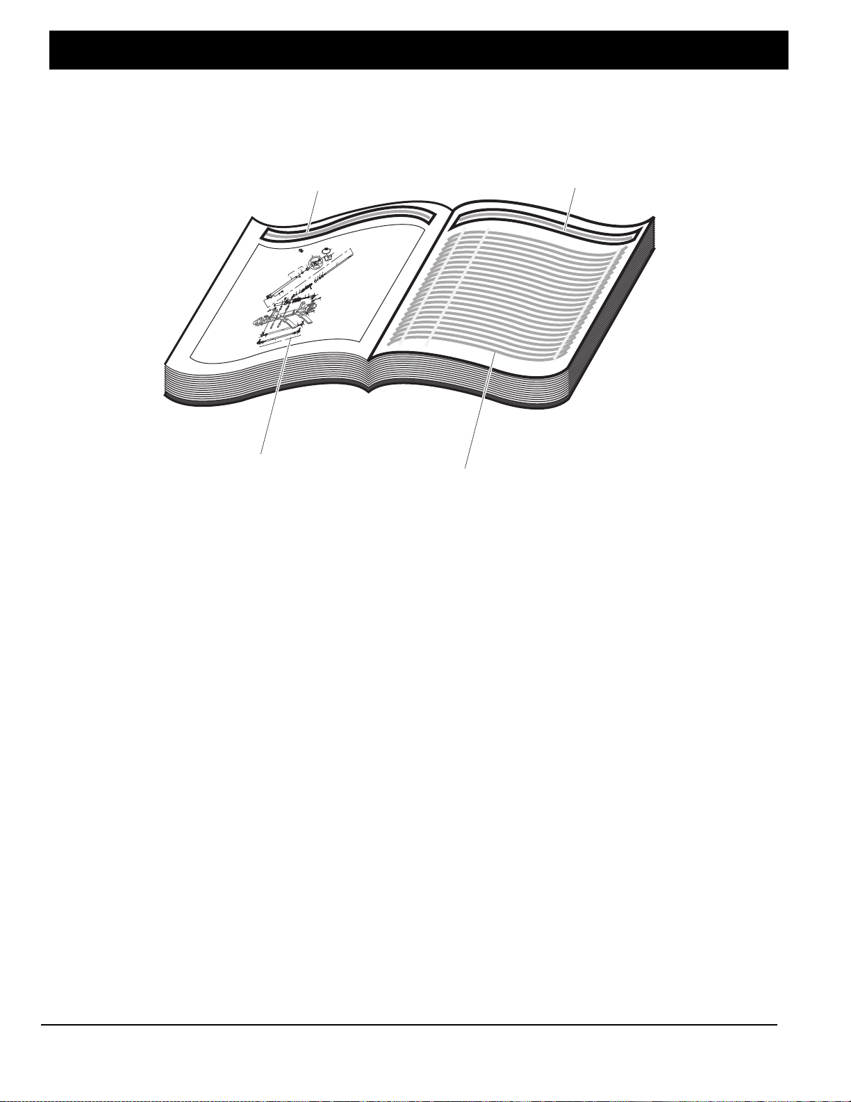
Title Title
Left hand
illustration page Parts list (continued on
rear of page if required)
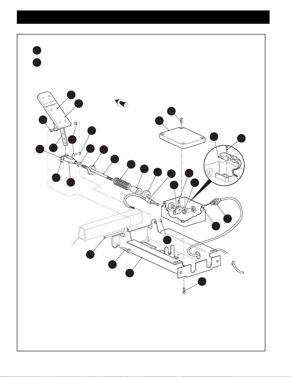
Front of Vehicle
123
101
100
99
98
120
74
70
71
64
63
65
66
67
121
122
114
119
115
111
73
72
112
118
116
113
62
69
94
96
95
82,87
81,86
84,89
83,88
102,104
105
79
91
92
107
106
62 - Includes Items 63 - 66, 69 - 74
70 -Incl
udes Items 71 - 74
81- Includes Items 82 - 84
86 - Includes Items 87 - 89
94 - Includes Items 95, 96
111 - Includes Items 112 - 114
118 - Includes Items 119 - 121
126 - Includes Items 127 - 131
103
*See Body Section for
decal information
127
128129
130
131
126

Page vii
Service Parts Manual
HOW TO USE THE SERVICE PARTS MANUAL
2. COLOR CODE FOR BODY COMPONENTS
The last two digits of the part number for the body part will denote the color code, locate the part number for the cowl,
rear body, seat pod, side panel or seat wrap then locate your color in lthe list below, replace the last ** or XX with the
two digit color code.
CODE # DESCRIPTION
11 BLACK
41 ELECTRIC BLUE

Page A-1
ACCELERATOR
653637 Service Parts Manual
To
Governor
Part of
Frame
5
25
4
23
3
39
35
2
22
9
10
8
28
12
13
14
15
11
18
19
17
21
20
19
32
33
31
16
4
7
6
1PEDAL BOX ASSEMBLY includes items 2 - 33
30 ACCELERATOR PEDAL ASSEMBLY includes items 31 - 33
Front of Vehicle

When ordering parts, please specify the model and serial number of the product.
* Indicates a component that is not available as an individual part.
*** Indicates consult Customer Service Department for additional information.
ITEM PARTNO. 12345 DESCRIPTION QTY.
Page A-2
ACCELERATOR
653637 Service Parts Manual
1 606990 PEDAL BOX ASSEMBLY (INCLUDES ITEMS 2 - 33) .................................... 1
2 652241G03 ACCELERATOR PEDAL BRACKET ........................................................ 1
3 01051G01 PAN HEAD PHILLIPS SCREW, #8 - 16 X 1/2" LG................................... 4
4 25853G03 PEDAL BOX AND COVER ....................................................................... 1
5 00684G6 TRUSS HEAD PHILLIPS SCREW (SS), #8 - 32 X 3/4" LG ..................... 2
6 25861G01 MICRO SWITCH, V-TYPE........................................................................ 1
7 01050G01 PAN HEAD TORX SCREW, #4 - 20 X 5/8" LG......................................... 2
8 72716G01 CAM (MICRO SWITCH) ........................................................................... 1
9 15126G1 LOCK NUT, 5/16" - 24 .............................................................................. 1
10 00487G3 SOCKET HEAD SCREW, 1/4" - 20 X 3/8" LG.......................................... 1
11 00532G4 HEX NUT, 5/16" - 24................................................................................. 2
12 17677G1 SPRING RETAINER................................................................................. 1
13 17979G1 ACCELERATOR ROD BUSHING............................................................. 1
14 73046G01 COMPRESSION SPRING........................................................................ 1
15 17677G2 SPRING RETAINER................................................................................. 1
16 72072G01 ACCELERATOR ROD .............................................................................. 1
17 10385G4 CLEVIS YOKE (ADJUSTABLE)................................................................ 1
18 10386G3 CLEVIS PIN, 5/16" X 13/16" LG ............................................................... 1
19 17838G1 BUSHING (NYLON), .313" I.D. X .374" O.D. X .312" LG ......................... 3
20 17255G1 TEFLON WASHER, 5/16" ........................................................................ 1
21 10387G3 COTTER PIN, 3/32" X 3/4" LG ................................................................. 1
22 74432G01 PEDAL PIVOT PIN ................................................................................... 1
23 12064G6 PUSH NUT, 5/16" ..................................................................................... 1
24
25 72201G04 WIRE HARNESS (PEDAL BOX) .............................................................. 1
26
27
28 608608 ACCELERATOR CABLE, 58.53" LG ........................................................ 1
29
30 25799G03 ACCELERATOR PEDAL ASSEMBLY (INCLUDES ITEMS 31- 33).......... 1
31 652824 ACCELERATOR PEDAL........................................................................ 1

Page A-3
When ordering parts, please specify the model and serial number of the product.
* Indicates a component that is not available as an individual part.
*** Indicates consult Customer Service Department for additional information.
ITEM PARTNO. 12345 DESCRIPTION QTY.
ACCELERATOR
653637 Service Parts Manual
32 16409G1 OVAL RIVET, 3/16" X 7/16" LG .............................................................. 6
33 27512G01 ACCELERATOR PEDAL PAD ................................................................ 1
34
35 00715G2 HEX WASHER HEAD SCREW, 5/16” - 18 X 3/4” LG...................................... 4

Page A-4
Notes:
ACCELERATOR
653637 Service Parts Manual

Page A-5
ACCELERATOR
653637 Service Parts Manual
DO NOT TAMPER WITH OR ATTEMPT TO CHANGE THE ADJUSTMENT OF THE
GOVERNOR. GOVERNOR TAMPERING CAN RESULT IN SERIOUS PERSONAL
INJURY AND WILL VOID THE VEHICLE WARRANTY.
608527
Rear Axle
1
6
8
9
10
11
11
12
19
12
14
7
2
3
4
5
To Direction Selector
Shifter Cable
Front of Vehicle
Front of Vehicle
FOR VEHICLES MANUFACTURED
FROM APRIL 20, 2014
FOR VEHICLES MANUFACTURED
UNTIL APRIL 19, 2014
Differential

When ordering parts, please specify the model and serial number of the product.
* Indicates a component that is not available as an individual part.
*** Indicates consult Customer Service Department for additional information.
ITEM PARTNO. 12345 DESCRIPTION QTY.
Page A-6
ACCELERATOR
653637 Service Parts Manual
1 606083 UPPER GOVERNOR BRACKET.................................................................... 1
2 606005 LOWER GOVERNOR BRACKET ................................................................... 1
3 73876G01 FLANGED HEX HEAD BOLT, M6 - 1 X 12MM LG.......................................... 1
4 606421 FLANGED HEX HEAD BOLT, M6 - 1 X 30MM LG.......................................... 1
5 450452 FLANGED HEX NUT, M6 - 1........................................................................... 1
6 606283 GOVERNOR LEVER BUSHING ..................................................................... 1
7 606284 GOVERNOR ROD .......................................................................................... 1
8 603890 GOVERNOR ROD GUARD ............................................................................ 1
9 606264 FLANGED HEX HEAD BOLT, M6 - 1 X 20MM LG.......................................... 1
10 606262 FLANGED HEX HEAD BOLT, M8 - 1.25 X 16MM LG..................................... 1
11 606074 GOVERNOR CABLE / DIRECTION SELECTOR BRACKET
(FOR VEHICLES MANUFACTURED UNTIL APRIL 19, 2014) ....................... 1
12 606256 FLANGED HEX HEAD BOLT, M10 - 1.25 X 25MM LG................................... 2
13
14 608527 GOVERNOR WARNING LABEL..................................................................... 1
15
16
17 17618G1 NYLON CLAMP, 8" LG (NOT ILLUSTRATED) ............................................... 2
18
19 632936 GOVERNOR CABLE / DIRECTION SELECTOR BRACKET
(FOR VEHICLES MANUFACTURED FROM APRIL 20, 2014)....................... 1

Page A-7
Notes:
ACCELERATOR
653637 Service Parts Manual

Page A-8
Notes:
ACCELERATOR
653637 Service Parts Manual

Page B-1
AIR FILTER
653637 Service Parts Manual
AIR FILTER ASSEMBLY includes items 2 - 6
1
8
9
2
10
11
56
4
3
7
Front of Vehicle

When ordering parts, please specify the model and serial number of the product.
* Indicates a component that is not available as an individual part.
*** Indicates consult Customer Service Department for additional information.
ITEM PARTNO. 12345 DESCRIPTION QTY.
Page B-2
AIR FILTER
653637 Service Parts Manual
1 658941 AIR FILTER ASSEMBLY (INCLUDES ITEMS 2 - 6) ....................................... 1
2 659139 AIR CLEANER ASSEMBLY...................................................................... 1
3 658957 AIR CLEANER COVER............................................................................ 1
4 72604G01 AIR CLEANER CLIP................................................................................. 2
5 28463G01 AIR FILTER .............................................................................................. 1
6 28462G01 DUST EJECTOR VALVE.......................................................................... 1
7 11391G7 HOSE CLAMP, 1.56"....................................................................................... 1
8 601910 HOSE, 44.5MM I.D. X 46.8MM O.D. X 14" LG............................................... 1
9 11391G1 HOSE CLAMP, 1.31"....................................................................................... 1
10 606261 FLANGED HEX HEAD BOLT, M8 - 1.25 X 20MM LG..................................... 2
11 606272 LOCK WASHER, 8MM.................................................................................... 2

Page B-3
Notes:
AIR FILTER
653637 Service Parts Manual
Other manuals for EZGO TXT VALOR
1
Table of contents
Other Textron Golf Car manuals

Textron
Textron EZGO TXT VALOR Guide

Textron
Textron EZ-GO Express L6 Guide

Textron
Textron E-Z-GO RXV Shuttle 2+2 Guide

Textron
Textron EZGO TXT FLEET Guide

Textron
Textron EZGO RXV 2016 User manual

Textron
Textron EZGO TXT FLEET 2010 User manual

Textron
Textron EZGO TXT ELiTE FREEDOM Guide

Textron
Textron EZGO TXT SHUTTLE 2+2 Guide

Textron
Textron Ezgo RXV-E User manual

Textron
Textron EZGO TXT FREEDOM Guide