Textron E-Z-GO RXV Shuttle 2+2 Guide

ISSUED MAY 2019
RXV Shuttle 2+2
Service Parts Manual
689390 - B
REVISEDAUGUST 2019


Page i
Service Parts Manual
SERVICE PARTS MANUAL
GASOLINE EFI POWERED GOLF CAR
RXV SHUTTLE 2+2
STARTING MID-MODEL YEAR 2019
Never modify the vehicle in any way that will alter the weight distribution of the vehicle, decrease its stability or increase the speed be-
yond the factory specifications. Such modifications can cause serious personal injury or death. Textron Specialized Vehicles prohibits
and dis-claims responsibility for any such modifications or any other alteration which would adversely affect the safety of the vehicle.
TSV reserves the right to incorporate engineering and design changes to products in this manual, without obligation to include these
changes on units sold previously.
The information contained in this manual may be revised periodically by TSV, and therefore is subject to change without notice.
TSV DISCLAIMS LIABILITY FOR ERRORS IN THIS MANUAL, and SPECIFICALLY DISCLAIMS LIABILITY FOR INCIDENTAL AND CONSE-
QUENTIAL DAMAGES resulting from the use of the information and materials in this manual.
These are the original instructions as defined by 2006/42/EC.
TO CONTACT US:
Textron Specialized Vehicles, Inc.
1451 Marvin Griffin Road
Augusta, Georgia, USA 30906-3852
NORTH AMERICA:
Technical Assistance & Warranty PHONE: 1-800-774-3946, FAX: 1-800-448-8124
Service Parts PHONE: 1-888-438-3946, FAX: 1-800-752-6175
International: PHONE: 001-706-798-4311, FAX: 001-706-771-4609

Page ii Service Parts Manual
GENERAL INFORMATION
To obtain a copy of the limited warranty applicable to the vehicle, call or write a local
Distributor, authorized Branch or the Warranty Department with vehicle serial number and
manufacturer code.
The use of non Original Equipment Manufacturer (OEM) approved parts may void the
warranty.
Tampering with or adjusting the governor to permit vehicle to operate at above factory
specifications will void the vehicle warranty.
When servicing engines, all adjustments and replacement components must be per original
vehicle specifications in order to maintain the United States of America Federal and State
emission certification applicable at the time of manufacture.
BATTERY PROLONGED STORAGE
All batteries will self discharge over time. The rate of self discharge varies depending on the
ambient temperature and the age and condition of the batteries.
A fully charged battery will not freeze in winter temperatures unless the temperature falls
below -75° F (-60° C).
BATTERY DISPOSAL
Lead-acid batteries are recyclable. Return whole scrap batteries to distributor, manufacturer
or lead smelter for recycling. For neutralized spills, place residue in acid-resistant
containers with absorbent material, sand or earth and dispose of in accordance with local,
state and federal regulations for acid and lead compounds. Contact local and/or state
environmental officials regarding disposal information.

Page iii
TABLE OF CONTENTS
Service Parts Manual
SECTION Page No.
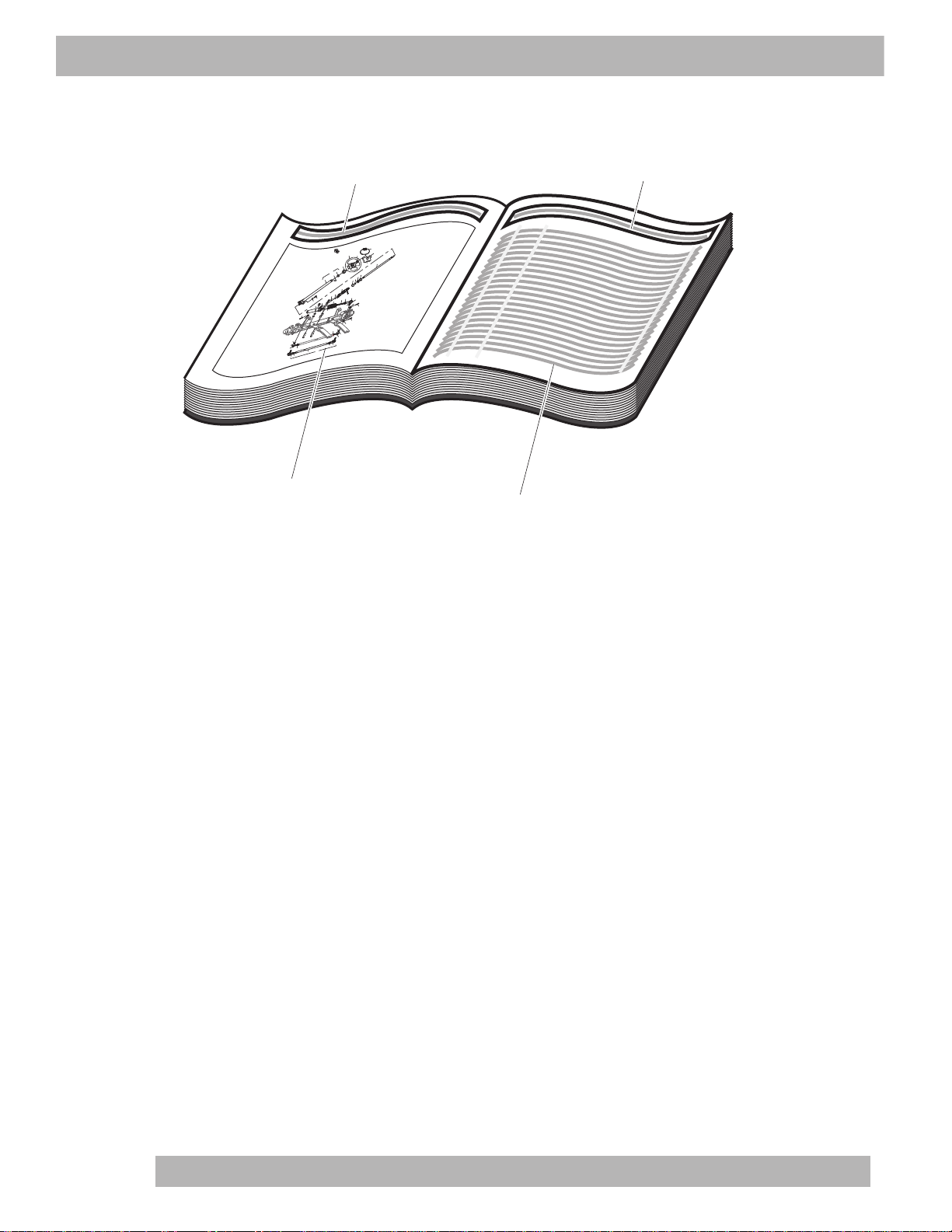
HOW TO USE THE SERVICE PARTS MANUAL. . . . . . . . . . . . . . . . . . . . . . . . . . . . . . . . . . . . . . . . . . . . . v
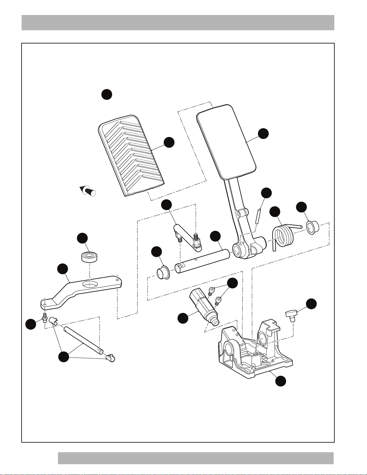
ACCELERATOR . . . . . . . . . . . . . . . . . . . . . . . . . . . . . . . . . . . . . . . . . . . . . . . . . . . . . . . . . . . . . . . . . . . . . A - 1
AIR FILTER . . . . . . . . . . . . . . . . . . . . . . . . . . . . . . . . . . . . . . . . . . . . . . . . . . . . . . . . . . . . . . . . . . . . . . . . . B - 1
BODY. . . . . . . . . . . . . . . . . . . . . . . . . . . . . . . . . . . . . . . . . . . . . . . . . . . . . . . . . . . . . . . . . . . . . . . . . . . . . . C - 1
BRAKES . . . . . . . . . . . . . . . . . . . . . . . . . . . . . . . . . . . . . . . . . . . . . . . . . . . . . . . . . . . . . . . . . . . . . . . . . . . D - 1
CLUTCH . . . . . . . . . . . . . . . . . . . . . . . . . . . . . . . . . . . . . . . . . . . . . . . . . . . . . . . . . . . . . . . . . . . . . . . . . . . E - 1
DIRECTION SELECTOR. . . . . . . . . . . . . . . . . . . . . . . . . . . . . . . . . . . . . . . . . . . . . . . . . . . . . . . . . . . . . . . F - 1
ELECTRICAL SYSTEM . . . . . . . . . . . . . . . . . . . . . . . . . . . . . . . . . . . . . . . . . . . . . . . . . . . . . . . . . . . . . . . G - 1
ENGINE AND MUFFLER . . . . . . . . . . . . . . . . . . . . . . . . . . . . . . . . . . . . . . . . . . . . . . . . . . . . . . . . . . . . . . H - 1
ENGINE MOUNTING. . . . . . . . . . . . . . . . . . . . . . . . . . . . . . . . . . . . . . . . . . . . . . . . . . . . . . . . . . . . . . . . . . J - 1
FRAME . . . . . . . . . . . . . . . . . . . . . . . . . . . . . . . . . . . . . . . . . . . . . . . . . . . . . . . . . . . . . . . . . . . . . . . . . . . . K - 1
FRONT SUSPENSION AND STEERING . . . . . . . . . . . . . . . . . . . . . . . . . . . . . . . . . . . . . . . . . . . . . . . . . . L - 1
FUEL SYSTEM . . . . . . . . . . . . . . . . . . . . . . . . . . . . . . . . . . . . . . . . . . . . . . . . . . . . . . . . . . . . . . . . . . . . . . M - 1
REAR AXLE . . . . . . . . . . . . . . . . . . . . . . . . . . . . . . . . . . . . . . . . . . . . . . . . . . . . . . . . . . . . . . . . . . . . . . . . N - 1
REAR SUSPENSION . . . . . . . . . . . . . . . . . . . . . . . . . . . . . . . . . . . . . . . . . . . . . . . . . . . . . . . . . . . . . . . . . P - 1
SEATING. . . . . . . . . . . . . . . . . . . . . . . . . . . . . . . . . . . . . . . . . . . . . . . . . . . . . . . . . . . . . . . . . . . . . . . . . . . R - 1
STARTER GENERATOR . . . . . . . . . . . . . . . . . . . . . . . . . . . . . . . . . . . . . . . . . . . . . . . . . . . . . . . . . . . . . . S - 1
WEATHER PROTECTION . . . . . . . . . . . . . . . . . . . . . . . . . . . . . . . . . . . . . . . . . . . . . . . . . . . . . . . . . . . . . T - 1
WHEELS AND TIRES . . . . . . . . . . . . . . . . . . . . . . . . . . . . . . . . . . . . . . . . . . . . . . . . . . . . . . . . . . . . . . . . . U - 1
DECALS AND LABELS . . . . . . . . . . . . . . . . . . . . . . . . . . . . . . . . . . . . . . . . . . . . . . . . . . . . . . . . . . . . . . . V - 1

Page iv
NOTES
Service Parts ManualService Parts Manual

Page v
Service Parts Manual
This manual is divided into several sections:
•GENERAL INFORMATION
•ILLUSTRATED PARTS BREAKDOWN
The first section, GENERAL INFORMATION, contains the following information:
•WARRANTY INFORMATION
•TABLE OF CONTENT
•HOW TO USE THE SERVICE PARTS MANUAL
The second section, ILLUSTRATED PARTS BREAKDOWN, contains illustrations and parts lists for all systems of your
vehicle.
USE OF THE MANUAL
To use this manual, consult the TABLE OF CONTENTS to locate the information or illustration required.
Introduction of some revisions varies due to supply of components; therefore, it is possible that various combinations of
components may be found that are not directly reflected by each illustration. Consult the illustration that best suits your
situation and then contact the Service Parts Department. It is important that the serial number or VIN of your vehicle and
the model name be supplied to Service Parts when ordering any replacement components.
HOW TO USE THE SERVICE PARTS MANUAL

Page vi Service Parts Manual
HOW TO USE THE SERVICE PARTS MANUAL
1. WHEN THE PART NUMBER IS NOT KNOWN
•Determine the function and application of the part required. Turn to the Table of Content and select the most
appropriate title.
•Turn to the page number indicated and locate the desired part on the illustration.
•From the illustration, obtain the item number assigned to the desired part. Refer to the accompanying
description for specific information regarding the part.
2. IF YOU KNOW THE PART NUMBER
•Locate the part number or description in the appropriate column on the parts list page.
NOTE: It is suggested that you confirm that the part selected is correct by verifying it with the pictorial representation on
the illustrated page.
Should an asterisk (*) appear in the part number column on the parts list page, read upwards until a part number is
found. The part number is the lowest assembly sold by Service Parts and the asterisk (*) indicates that the part depicted
is not available for purchase.
NOTE: Descriptions are indented under the assembly that they are used on. That assembly is, in turn listed under the
assembly that it is used on. This process is repeated until the highest final assembly is reached.
To facilitate the maintenance and repair of the vehicle, a Repair and Service Manual is available from
the Service Parts Department.
Title Title
Left hand
illustration page Parts list (continued on
rear of page if required)
Front of Vehicle
123
101
100
99
98
120
74
70
71
64
63
65
66
67
121
122
114
119
115
111
73
72
112
118
116
113
62
69
94
96
95
82,87
81,86
84,89
83,88
102,104
105
79
91
92
107
106
62 - Includes Items 63 - 66, 69 - 74
70 -Incl
udes Items 71 - 74
81- Includes Items 82 - 84
86 - Includes Items 87 - 89
94 - Includes Items 95, 96
111 - Includes Items 112 - 114
118 - Includes Items 119 - 121
126 - Includes Items 127 - 131
103
*See Body Section for
decal information
127
128129
130
131
126

Page vii
Service Parts Manual
3. COLOR CODE FOR BODY COMPONENTS
The last two digits of the part number for the body part will denote the color code, locate the part number for the cowl,
rear body, seat pod, side panel or seat wrap then locate your color in the list below, replace the last ** or XX with the two
digit color code.
CODE # DESCRIPTION
02 SPECIAL COLOR
11 BLACK
19 PATRIOT BLUE PEARL
20 INFERNO RED METALLIC
26 STEEL BLUE PEARL
31 METALLIC CHARCOAL
36 IVORY
37 FOREST GREEN
38 BRIGHT WHITE
39 FLAME RED
41 ELECTRIC BLUE
42 PLATINUM
43 BURGUNDY
44 ALMOND
51 SUNBURST ORANGE
52 BRITISH RACING GREEN
74 BARLEY GOLD
75 OASIS GREEN
76 JAVA BROWN
HOW TO USE THE SERVICE PARTS MANUAL

Page A-1 689390 Service Parts Manual
ACCELERATOR
2
3
15
16
6
8
4
14
9
10
11
17
5
4
7
1Accelerator Pedal Assembly includes items 2 - 17
Front of Vehicle
12

THE USE OF NON U.L. PARTS WILL VOID ANY U.L. LISTING.
When ordering parts, please specify the model and serial number of the product.
* Indicates a component that is not available as an individual part.
*** Indicates consult Customer Service Department for additional information.
ITEM PARTNO. 12345 DESCRIPTION QTY.
Page A-2
689390 Service Parts Manual
ACCELERATOR
1 653202 Accelerator Pedal Assembly (Includes Items 2 - 17)........................................ 1
2 * Pedal Bracket ............................................................................................ 1
3 * Pedal ......................................................................................................... 1
4 * Flanged Bushing, 16mm x 12mm.............................................................. 2
5 * Pivot Shaft, 16mm ..................................................................................... 1
6 600683 Spirol Pin (Heavy Duty), 4mm x 26mm ..................................................... 1
7 * Torsion Spring, 4.5mm Dia ........................................................................ 1
8 604097 Rebound Bumper ...................................................................................... 1
9 603808 Ball Bearing ............................................................................................... 1
10 600702 Bell crank Arm ........................................................................................... 1
11 604475 Ball Stud, 6mm Dia.................................................................................... 1
12 668945 Linkage Rod Saddle Clip Assembly........................................................... 1
13
14 603816 Ball Joint Rod Assembly ............................................................................ 1
15 610529 Pedal Cover............................................................................................... 1
16 620030 Socket Head Bolt, M5 - .8 x 15mm Lg....................................................... 2
17 612889 Pedal Switch.............................................................................................. 1

Page A-3 689390 Service Parts Manual
ACCELERATOR
Front of Vehicle
1
5
7
6
4
15
11
18
12
20
19
23
13
22 24
Rear Axle
Engine
Front of Vehicle
16
26
To Direction Selector
Shifter Cable
To Accelerator
Bracket

THE USE OF NON U.L. PARTS WILL VOID ANY U.L. LISTING.
When ordering parts, please specify the model and serial number of the product.
* Indicates a component that is not available as an individual part.
*** Indicates consult Customer Service Department for additional information.
ITEM PARTNO. 12345 DESCRIPTION QTY.
Page A-4
689390 Service Parts Manual
ACCELERATOR
1 609849 Accelerator Cable............................................................................................. 1
2
3
4 608290 Pan Head Phillips Screw, #10 - 16 x 3/4" Lg.................................................... 2
5 604536 Socket Head Shoulder Bolt, M8 - 1.25 x 20mm Lg .......................................... 1
6 649803 Pan Head Torx Screw, M6 - 2.65 x 25mm Lg................................................... 3
7 614393 Pedal Insert ...................................................................................................... 1
8
9
10
11 606005 Governor Bracket (Lower)................................................................................ 1
12 606284 Governor Link Rod ........................................................................................... 1
13 660005 Governor Guard Bracket .................................................................................. 1
14
15 606083 Governor Bracket (Upper)................................................................................ 1
16 632936 Governor Cable/Direction Selector Bracket ..................................................... 1
17
18 606283 Governor Lever Bushing .................................................................................. 1
19 606421 Flanged Hex Head Bolt, M6 - 1 x 30mm Lg, Grade 8.8 ................................... 1
20 606256 Flanged Hex Head Bolt, M10 - 1.25 x 25mm Lg, Grade 8.8 ............................ 2
21
22 606264 Flanged Hex Head Bolt, M6 - 1 x 20mm Lg, Grade 8.8 ................................... 1
23 73876G01 Flanged Hex Head Bolt, M6 - 1 x 12mm Lg, Grade 8.8 ................................... 1
24 601476 Lock Nut M6 - 1................................................................................................ 1
25
26 450452 Flanged Hex Nut, M6 - 1 .................................................................................. 1

Page A-5 689390 Service Parts Manual
Notes:
ACCELERATOR

Page A-6
689390 Service Parts Manual
Notes:
ACCELERATOR

Page B-1 689390 Service Parts Manual
AIR FILTER
6
5
4
32
9
16
10
1
7
Front of Vehicle
Canister Bracket
Air Cleaner Assembly includes items 2 - 7
11
12
1
13
14

THE USE OF NON U.L. PARTS WILL VOID ANY U.L. LISTING.
When ordering parts, please specify the model and serial number of the product.
* Indicates a component that is not available as an individual part.
*** Indicates consult Customer Service Department for additional information.
ITEM PARTNO. 12345 DESCRIPTION QTY.
Page B-2
689390 Service Parts Manual
AIR FILTER
1 688989 Air Cleaner Assembly (Includes Items 2 - 7) .................................................... 1
2 28462G01 Dust Ejector Valve ..................................................................................... 1
3 72604G01 Air Cleaner Clip ......................................................................................... 2
4 691746 Air Cleaner Cover ...................................................................................... 1
5 28463G01 Air Filter ..................................................................................................... 1
6 689988 Air Cleaner Housing .................................................................................. 1
7 689987 Air Cleaner Seal ........................................................................................ 1
8
9 601910 Air Filter Hose, 14" Lg ...................................................................................... 1
10 11391G7 Hose Clamp, 1.56" ........................................................................................... 1
11 606261 Flanged Hex Head Bolt, M8 - 1.25 x 20mm Lg, Grade 8.8 .............................. 2
12 606272 Lock Washer, 8mm .......................................................................................... 2
13 11391G7 Hose Clamp, 1.56" ........................................................................................... 1
14 661663 Intake Extension Hose .................................................................................... 1
15 12416G2 Nylon Clamp, 15.5" Lg (Not Illustrated) ........................................................... 1
16 11391G5 Hose Clamp, .81" ............................................................................................. 1

Page B-3 689390 Service Parts Manual
Notes:
AIR FILTER

Page B-4
689390 Service Parts Manual
Notes:
AIR FILTER

689390 Service Parts Manual
Page C-1
BODY
1
4
12
10
27
28
5
21
20
11
17
6
18
19
7
8
5Instrument Panel includes item 6
7Access Cover Assembly (IP) includes item 8
Front of Vehicle
29
30
Instrument Panel
23
Table of contents
Other Textron Golf Car manuals

Textron
Textron EZGO TXT ELiTE FREEDOM Guide

Textron
Textron E-Z-GO RXV Series User manual

Textron
Textron EZGO RXV 2016 User manual

Textron
Textron EZGO TXT FREEDOM Guide

Textron
Textron Ezgo RXV-E User manual

Textron
Textron EZGO TXT FLEET 2010 User manual

Textron
Textron EZGO TXT SHUTTLE 2+2 Guide

Textron
Textron EZGO RXV ELiTE FLEET Guide

Textron
Textron EZGO TXT VALOR Guide

Textron
Textron EZ-GO Express L6 Guide