Teyme ASM1-200-24 User manual
www.teyme.es
Lift-mounted Mistblower
Notice of Instructions
T990000005 – 05.2019
ES – Versión 1.0

Mistblowers Notice of Instructions
Page 1 of 43
Contents
1.
Basics 4
1.1.
Responsibility 4
1.2.
Legal Warranty 4
1.3.
Optional Accessories 4
1.4.
Declaration of Conformity 4
1.5.
Identification Plate 6
2.
Safety and Protection 6
2.1.
Classification of symbols by dangerousness 6
2.2.
Group of Addressees
2.3.
Proper Use
2.4.
Recommendations for Caution
2.5.
Rules and Applicable Prescriptions 8
2.6.
Allowed Weights of the machine 8
2.7.
Tractor’s requirements 8
2.8.
Obligations of the user .8
2.9.
Safe workings of the machine .9
2.9.1.
Basics .9
2.9.2.
Staff qualification. .9
3.
Effects of certain agrochemicals over the machine .9
4.
Description 10
4.1.
General information ..10
4.1.1.
General View 10
4.1.2.
Use of the sprayer 11
4.1.3.
Road traffic 11
4.1.4.
Frame 12
4.1.5.
Tanks 12
4.2.
Water Circuit 12
4.2.1.
General Information 12
4.2.2.
Water Circuit Diagram 12
4.2.3.
Suction Valve 13
4.2.4.
Suction Filter 13
4.2.5.
Pumps 13
4.2.6.
Pressure Filter 14
4.2.7.
Stirrers 14

Mistblowers Notice of Instructions
Page of 43
4.2.8.
Distributor 15
4.2.9.
Can Rinsing 15
4.2.10.
Mixer/chemical inductor (optional) 15
4.2.11.
Jets or nozzle-holders 16
4.2.12.
Tank Rinsing Robot 16
4.3.
Air Unit 16
4.3.1.
General Information 16
4.3.2.
Models of air units 16
4.3.3.
Air Flow of the Units 1
4.3.4.
Protection Grid 20
4.3.5.
Gear Box 20
4.3.6.
Impeller or Fan 20
4.3.7.
Deflectors (Air Deflectors) 21
4.4 . Furnishing 21
4.4.1 Lights Kit (in option) 21
5.
Adjustments and how to start up 1
5.1.
Machine’s Load or Unload 21
5.2.
PTO Shaft 21
5.2.1.
PTO Shaft Coupling 22
5.3.
Hydraulic Plugs 22
5.4.
Electrical Plugs 23
5.4.1.
Basics 23
5.4.2.
Lighting and Signs (Optional) 23
5.4.3.
Water Distributor 23
5.5.
Water Circuit 24
5.5.1.
Suction Filter 24
5.5.2.
Piston Pump 24
5.5.3.
Diaphragm Pump 24
5.5.4.
Air Tank 24
5.6.
Air Unit 25
5.6.1.
Gear Box 25
5.6.2.
Fan 25
6.
Working 7
6.1.
Water Circuit 2
6.1.1.
Filling of the Main Tank 2
6.1.2.
Filling of the Rinsing Can 2
6.1.3.
Filling of the Sanitary Water Tank 2

Mistblowers Notice of Instructions
Page 3 of 43
6.2.
Emptying Valve 28
6.3.
Introduction of Phytosanitary Product 28
6.3.1.
Chemical Inductor/Mixer (optional) 28
6.3.2.
Powder Mixer 28
6.4.
Cleaning of the Water System 28
6.4.1.
Cleaning of Filters 29
6.5.
Controls 29
6.5.1.
GRH Hand-operated Control 29
6.5.2.
System 1 Electrical Distributor 30
6.5.3.
System 2 Electrical Distributor 31
6.5.4.
System 3 Electrical Distributor 31
6.5.5.
BRAVO 180 Electrical Distributor 34
6.5.6.
SONAR MCK Electrical Distributor 3
6.6.
Air Kit 38
6.6.1.
Deflectors (Air Deflectors) 39
7.
Maintenance 39
7.1.
General Information 39
7.2.
PTO Axle and PTO Shaft 39
7.3.
Water Pumps 40
7.3.1.
Ordinary Maintenance 40
7.3.2.
Extraordinary Maintenance 40
7.4.
Gear Box Unit 40
7.5.
Fans 40
7.6.
Filters and Fittings 40
7.7.
Nozzles 41
7.8.
Winter Storage 41
7.9.
Preparation of the Machine to use it after its Storage 42
7.10.
Periods of Maintenance 42
7.10.1.
Every 10 Working Hours. 42
7.10.2.
Every 50 Working Hours 42
7.10.3.
Every 250 Working Hours. 42
7.10.4.
Every 1000 Working Hours 42
8.
Failures Detection 42
8.1.
General Information 42
8.2.
Liquid Circuit 43

Mistblowers Notice of Instructions
Page 4 of 43
1. BASICS
1.1.
Responsibility
They are of application the “General Conditions of Contract and of Delivery” of Teyme Tecnología Agrícola, S.L.
According to these conditions, it is excluded any responsibility on behalf of Teyme Tecnología Agrícola for personal
and material damages caused by any or several of these reasons:
•
Unadequate use of the machine.
•
Not having read the instructions of use as well as the safety indications included on these.
•
Constructive modifications of the machine made on one’s own.
•
Defficient control of the pieces submitted to wear.
•
Repair works which have not been correctly done or not done in the expected delays.
•
Use of other spare parts which are not original from the company Teyme tecnología agrícola.
•
Accidents or damages caused by external reasons or overwhelming forces.
1. .
Legal Warranty
They will be of application the “Conditions of contract and delivery” of the company Teyme Tecnología Agrícola, S.L..
The period of duration of the legal warranty includes a year since the machine has been received. We will solve the
possible failures in the machine following the guidelines given by TEYME’s legal warranty.
1.3.
Optional Accessories
The machines of TEYME can be supplied with optional accessories. The notice of use will describe the standard
components as well as the optional ones.
We remind that these will differ depending on each variable of the supplied machine.
1.4.
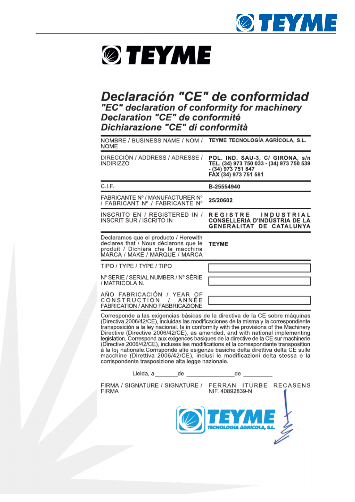
Declaration of Conformity
Mistblowers Notice of Instructions
Page 5 of 43

Mistblowers Notice of Instructions
Page 6 of 43
1.5.
Identification Plate
The identification plate, placed in the right front part of the machine and riveted to the structure of the frame indicates
the brand, the model, the serial number and the date of manufacture.
The serial number is also found die-cast on the frame of the machine. In the upper part of the right ear of the lower
braces.
1* Position of the identification plate
2* Position of the number of chassis
.
Safety and protection
.1.
Classification of symbols by dangerousness
This symbol means DANGER. Be careful as your safety is in danger!
This symbol means CAUTION Be aware as your safety is at stake!
This symbol means ATTENTION. It will help you to an easy and safe use.

Mistblowers Notice of Instructions
Page 7 of 43
. .
Group of addressees
This notice of use limits exclusively the use of the machine to qualified staff, as well as to well-instructed personnel.
.3.
Proper Use
The machine has been built up according to the latest technical advances and reputed technical safety rules. However,
it is probable that, during its use, dangers may appear for the life and for the physical integrity of the user or of third
parties, as well as damages in the machine or other material impairments. Work only with the machine if you find it in
a correct technical condition and use it properly, accordingly with the notice of use and being conscious about the
safety and the dangers.
The proper use also includes
•the understanding and observance of the instructions of use and the application of the work steps indicated
in these.
•The observance of the safety and caution signals in the machine.
•
The observance of the limits of power of the tractor and machine.
•The observance of the indications of maintenance, as well as of the further verifications.
•The use of original spare parts.
•The use of indicated oil and accessory substances, as well as their suppression respectful with the
Environment.
The safe working is only guaranteed if all indications, adjustments and valid power limits for the machine are respected.
The machine is only suitable for its use in agricultural jobs.
.4.
Recommendations for Caution
Please consider the following recommendations for caution.
Read thoroughly this notice of instructions before using the machine. It is equally important that other
users that will operate with the machine, read and understand this notice of instructions.
Some local laws can require that the operator has a certificate to be able to use the machine. Please be
ware of the law.
Use suitable protection garment (gloves, helmet, waterproof clothes, etc).
Clean and rince the machine after its use and before its revision.
Do not ever check or repair the machine while this is working.
Replace always the safety devices and protect them immediately after work.
Do not eat, drink or smoke while you are spraying or working with the machine dirty.
Clean and change your clothes after the spraying. Clean the used tools.

Mistblowers Notice of Instructions
Page 8 of 43
In case of poisoning call the medical services. Do not forget to identify the chemicals.
Keep children away from the machine.
If some part of this notice of instructions is not completely clear to you, do not hesitate to contact your TEYME’s
dealer for a more extensive explanation before using the machine.
Be careful not to hit people or surroundings while manoeuvring with the sprayer, specially while this one is turning.
Diminish the speed while circulating on rough plots as there is danger of rollover.
Check the pressure with clean water before carrying out the filling of chemicals.
Disconnect the electric current and depressurize the machine after its use and before its checking.
Do not try to enter the tank.
Do not stay under the sprayer when this is not well secured to avoid some falling down or running over.
If you use a welding arch on the machine, turn off all electrical devices before starting with the welding. Keep yourself
away from any explosive or inflammable material.
Do not unplug any hose while the machine is working. Unplug the cleaner and the water supply before disassembling
the high-pressure hose.
The device of external cleaning should not be used when any important part of the machine is damaged, including
safety devices, high pressure, etc.
ON NO ACCOUNT the PTO shaft of the tractor must overcome the 540 r.p.m. due to the big danger of explosion of
the air unit.
.5.
Rules and Applicable Prescriptions
Herewith they are specified the valid applicable rules for each country, which must be taken into account during the
machine’s working life:
•
Road Traffic code.
•
The rules and regulations about labour safety
•
The rules and regulations about road traffic safety.
•
The rules and regulations about the user’s protection.
•
The rules and regulations about protection of the environment.
•
The rules and regulations about the proper handling of pesticide products.
•
The rules and regulations on plants’ protection technology.
.6.
Allowed weights of the machine
The weight of the machine is transmitted through the hitching points disposed for this fonction.
For this reason, the following points must be considered for a safe working of the machine:
•
The allowed supporting load for the tractor’s hitching must not be exceeded.
.7.
Requirements for the tractor
•
The tractor must have a hitching appropriate for the machine (Cat-I, II and IIN).
•
On basis of the established applicable regulations, there must be an appropriate brakes’ device available in the
tractor.

Mistblowers Notice of Instructions
Page 9 of 43
•
The tractor must have a protection for the PTO shaft which proves to be appropiate for the machine.
•
The tractor’s hydraulic system must be compatible with the machine.
•
There must be available in the machine appropriate electrical connections.
•
The allowed limit of power of the tractor must be respected.
.8.
Obligations of the User
Before starting up, read the handling instructions.
•Respect the indications of safety.
•To carry out all works, use the corresponding protection clothes. This one must fit the body.
•Respect and complete the handling instructions with the general legal regulation and other bonding regulations
about accidents prevention and environmental protection.
•The handling instructions are an important component of the machine.
•Beware that the handling instructions are always available where the machine is working and that they are preserved during
its full lifetime.
•In case of sale or owner’s change, hand in the handling instructions with the machine.
•Keep all the safety and danger warnings in a readable and complete estatus. The warning and safety symbols give
valuous information to work without danger. The observance is for your own safety.
•Any modification standing for attachments or machine reconstruction which could damage safety can not be done
without the authorisation of the manufacturer. The manufactured is excluded from any responsibility for any
ensuing damange because of modifications done on one’s behalf in the machine.
•Use the machine with full respect for all connection and adjustment values determined by the manufacturer.
•Use only original spare parts.
.9.
Safe working of the machine
2.9.1.
Basics
Before starting the work, get to know all devices and starting elements, as well as their fonctions.
•
Turn on and start up the machine just if all the protection devices are mounted and whenever they are in
protection mode.
•
Assemble always the machine according to the current regulations and only in the couplings contemplated in
these.
•
Proceed most carefully to carry out the assembly and disassembly of the machine in or out of the tractor.
It is forbidden to remain in the dangerous area of the machine and step over this one while this is working.
In the parts triggered by external forces there may exist danger of squashing and cuts.
•Activate the hydraulic devices only when there is no person in the danger area.
•Do not stay in the area between the tractor and the machine. This is only allowed if the tractor and the
machine are secured against rolling by means of the parking brake and stopping chocks.
•
Keep the machine always clean to avoid danger of fire.
2.9.2.
Staff qualification
•
The driver of the tractor must have the corresponding driving license available.
•
All the works in the machine must be exclusively done by instructed and trained staff. The personnel must not be under
the effect of drugs, alcohol or medicines.
•
The works of maintenance and care will only have to be carried out by instructed specialized staff or by
people suitably trained.
•
The works in the electrical parts must only be carried out by electricians according to the applicable electrotechnical
regulation.

Mistblowers Notice of Instructions
Page 10 of 43
3.
Effects of certain agrochemicals on the machine
Some admitted pesticides and mixtures can have harmful effects on materials of the sprinkler. Basically, they are
sprinkling means and mixtures with solvent.
CAUTION! When using mixtures with sprinkling methods with acknowledged harmful effects, it
is recommended to test the mentioned materials before starting the works, by means of
inversion tests during several hours. The pesticides or other products which use to become
solid or sticky can not be used in the machine.
CAUTION! Follow necessarily the indications of the manufacturer of the pesticide before
starting to work.
The following components of the machines can suffer from damages: hoses, sprinkling pipes, joints, tanks, pump’s
diaphragms and nozzle-valves diaphragms.
Too soft hoses or swollen joints or diaphragms are symptoms of these harmful effects. The damaged pieces must
be immediately replaced. These pernicious effects can be avoided if, immediately after its use, an intensive
cleaning is done (for example, some rinsing and suppression of the technical remains in the crop).
4.
Description
General information
4.1.1. General View

Mistblowers Notice of Instructions
Page 11 of 43
1. Control Box
2. General water control
3. Base machine
4. Pump
5. Air Unit
6. Deflector
. Footrest
4.1.1.
Use of the sprayer
TEYME’s sprayer is designed for the application of chemical products for crops’ protection. The machine can be
only used with this purpose. It is not allowed the use of this equipment for other purposes. If the local laws do
not compel the operator to be certified, it is recommendable to be instructed in order to carry out a correct
protection of crops and a safe handling of the chemicals to avoid an unnecessary risk for people and the
environment while the spraying is done.
4.1.2.
Road traffic
You should furnish your machine with and follow the next regulations when driving by public roads and other
places where it is applicable the traffic code, or places where there are special laws and regulations about signs
and lights on agricultural tools
Mistblowers Notice of Instructions
Page 1 of 43
4.1.3.
Frame
The frame consists in structural tubes, attached by some crossbars in a specific design, which furnishes the whole of a high
toughness and resistance to face usual and high demands of use. To protect it from corrosion a primer of epoxi is applied
and covered by highly adhesive monolayer polyurethane painting.
4.1.4.
Tanks
The main tank is made of polyethylene and is resistant to impacts, to the UV rays and to chemical products. It has
a round design without corners for a better cleaning and emptying. Nominal capacity 53, 9, 105, 158, 211, 264
and 31 gal. It has a transparent gauge located in the right front part of the tank that can be seen from the
tractor. The filling mouth is in the left upper part and one can get access to it from a footrest step, depending on
the capacity of the tank. That enables the filling of the tank and insertion of chemicals.
Next to the main tank it can be found a clean water tank or rinsing tank of 10% capacity out of the main tank.
And a sanitary water tank of about 4 gallons of capacity.
4.2. Water Circuit
4.2.1. General information
All sprayers include a high-pressure water circuit to carry out an efficient treatment and to obtain a homogeneous
mixture of the product.
4.2.2.
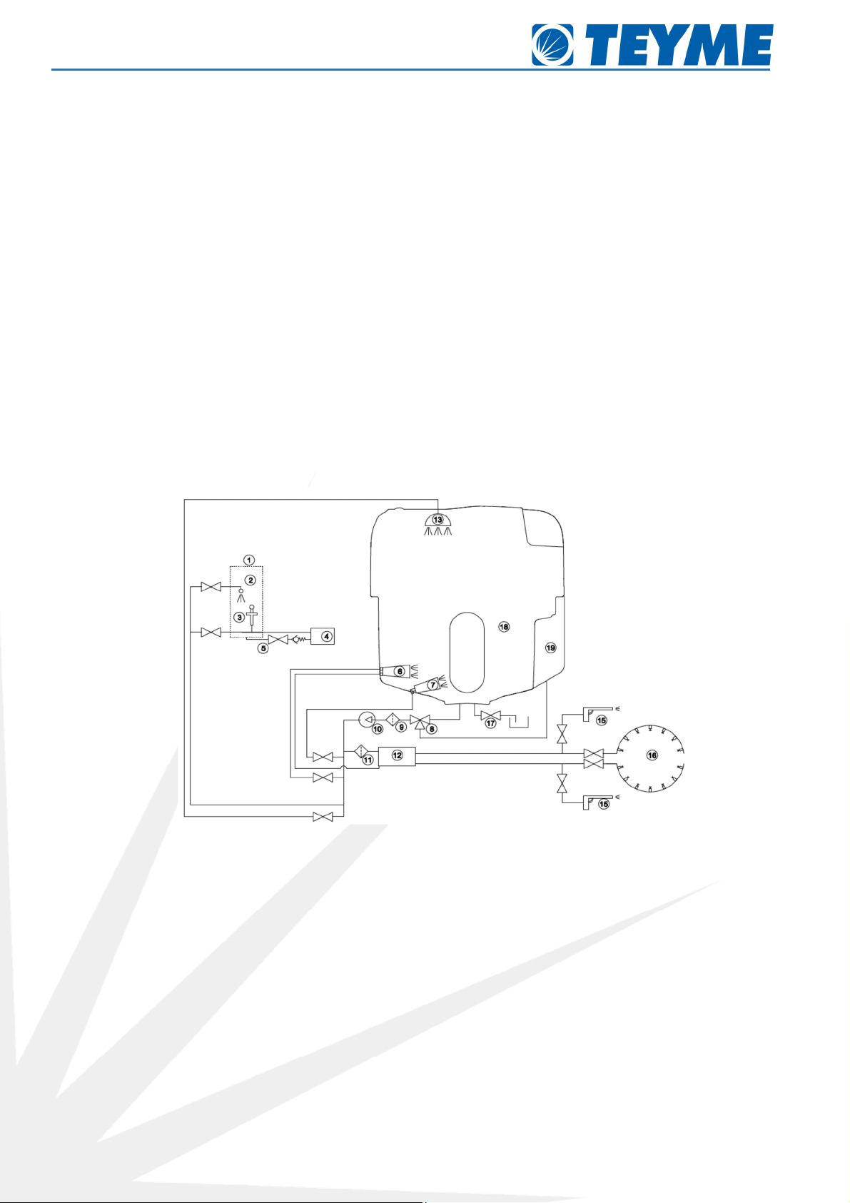
Water Circuit Diagram
1 Mixer- chemical inductor 11 Pressure Filter
2 Stirrer-product mixer 12 Water Distributor
3 Can-rinsing robot 13 Tank-Rinsing robot
4 Mixer ventouri suction 14 Powder mixer
5 Mixer Draining Valve 15 Spraying Guns
6 Euromix (stirrer) 16 Jets or nozzle-holderss
Hydraulic stirrer (bottom stirrer) 1 Main tank draining valve
8 Three ways valve 18 Main Tank
9 Suction filter 19 Rinsing Tank
10 Water pump
Mistblowers Notice of Instructions
Page 13 of 43
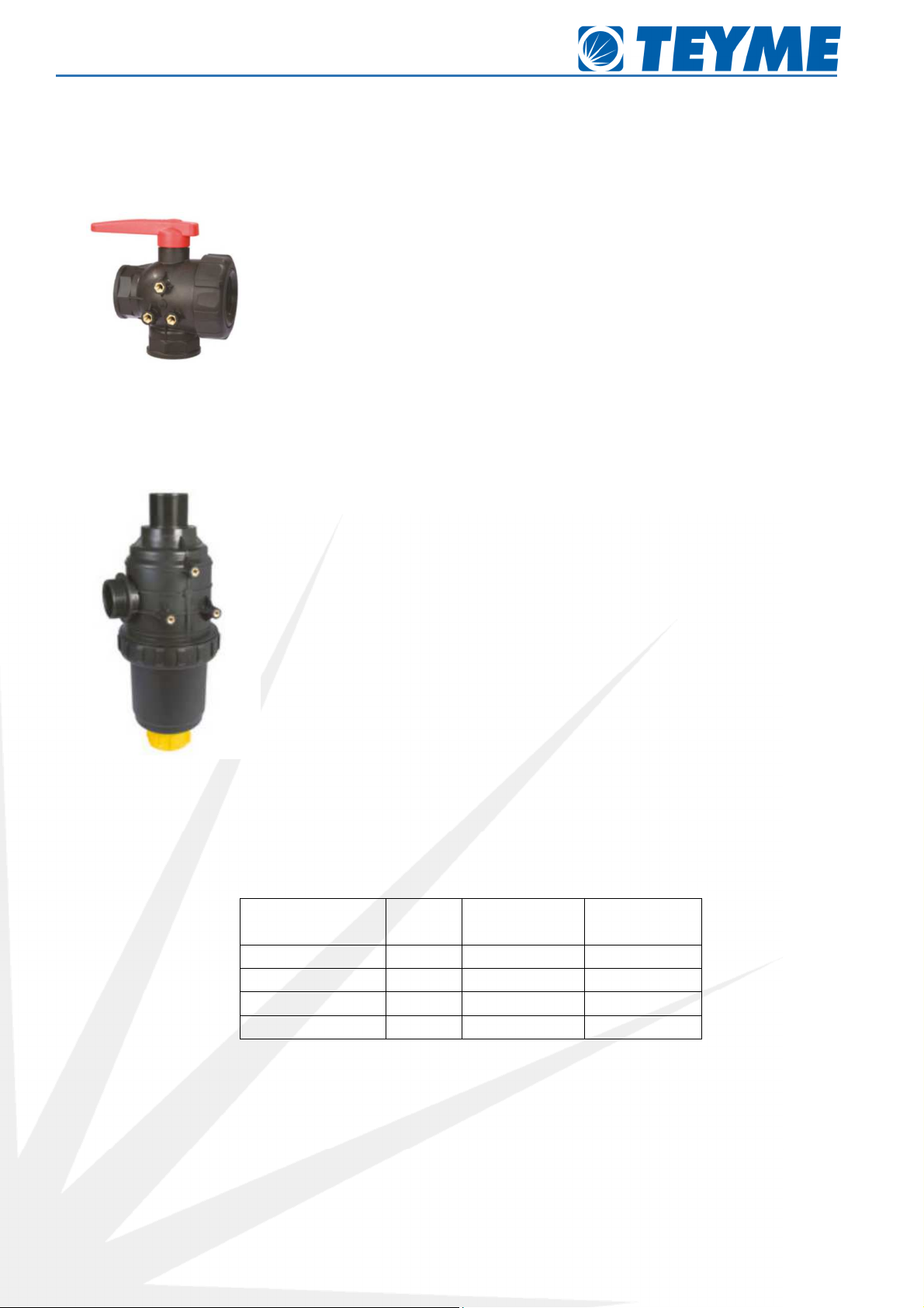
4.2.3. Suction Valve
The suction valve is placed to the right of the pump and allows to choose the tank from which the pump will suck, which
can be the main tank to carry out the spraying tasks or the rinsing tank to clean the inside of the liquid circuit. The tank
can be selected turning the lever of the valve towards the desired function.
4.2.4. Suction Filter
Next to the suction valve there is the suction filter with an inox grid of 50 mesh. They have an automatic closing valve for
filter cleaning, auxiliary suction entry to fill in the tank and cap for valve’s activation.
4.2.5. Pumps
4.2.5.1. High Pressure Piston Pumps
High pressure toughly-built-up pumps. Immersed pistons with ceramic cases. Parts with contact with fluid are
manufactured in anodized aluminium.
Sort of pump Flow rate
(gpm)
Highest pressure
(psi)
Num. of pistons
Comet YA 65 Pump 12,42 8 0 3
Comet YA 5 Pump 15,32 8 0 3
Comet YA 130 Pump 24,1 8 0 6
Comet YA 150 Pump 29,85 8 0 6
4.2.5.2. High Pressure Diaphragm Pumps
High pressure toughly-built-up pumps. They include pressure accumulator and safety valve. NBR diaphragms, parts with
contact with the liquid manufactured in anodized aluminium and AISI 303/304.
Mistblowers Notice of Instructions
Page 14 of 43
Sort of pump Flow rate
(gpm)
Highest Pressure
(psi)
Num of diaphragms
Comet APS-121S pump 30,38 25 3
Comet APS-51 pump 13,39 25 3
Comet APS-61 pump 16,30 25 3
Comet APS- 1 pump 1 , 5 25 3
Comet APS-96 pump 23,25 25 4
Teyme AR-150 pump 3 ,60 25 4
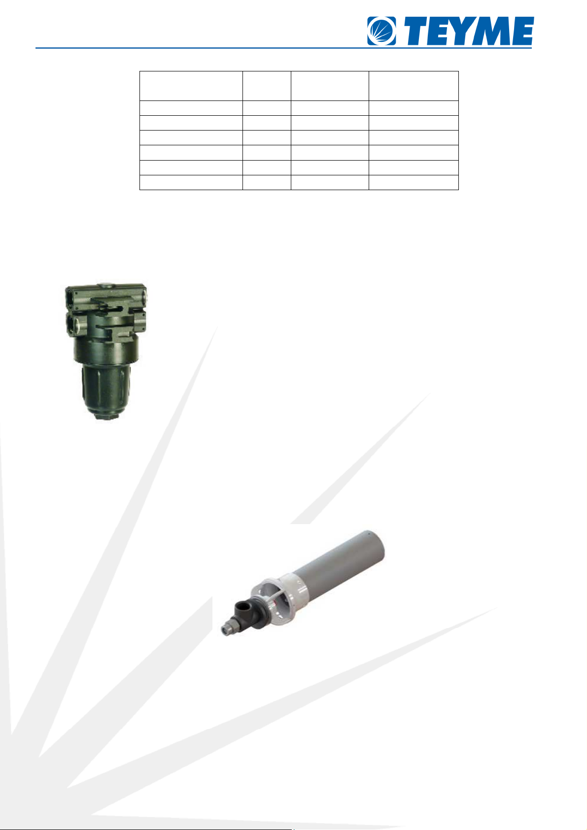
4.2.6. Pressure Filter
It is placed on the exit of the pump or placed in the middle of the distributor, with an inox grid VITON watertight o’ring
sealed in the cap. Highest working pressure 25 psi. All the filters must be on perfect conditions and regularly cleaned.
Beware for choosing a proper combination of filter and grid mesh size. The grid mesh size must be always lower to the
average total flow rate of the nozzles.
4.2.7. Stirrers
Inside the tank we can find a two-ways “trumpet”-type stirrer (Euromix). This stirrer is triggered by means of two of the
valves.
In the left lower part of the tank a stirrer is located that stirs the bottoms of the tank. Depending on the capacity of the
tank, there can be another bottom stirrer, laid in the right lower part of the tank. They are triggered by means of a valve.
In the inner lodge of each one there is a 0,10 inches diameter restrictor (D).

Mistblowers Notice of Instructions
Page 15 of 43
4.2.8.
Distributor
The sprayer can be provided with different sorts of distributors to control the spraying.
4.2.8.1. GR and-operated Distributor
Distributor with a single-control lever for the spraying selection. A knob is included to raise or lower pressure and a
manometer.
DANGER!
It is forbidden to use this sort of control in tractors with closed cab.
4.2.8.2. System 1 Electrical Distributor
Electrical distributor with control box which allows to open and close right and left sides independently. It includes pilot
light warning about the opening of sector. This distributor includes pressure compensation valves and pressure hand-
operated regulation.
4.2.8.3. System 2 Electrical Distributor
It has the same fonctions as system 1. Additionally, it allows pressure regulation by an electrical valve and it includes an
added selector on the control board.
4.2.8.4. System 3 Electrical Distributor
With the same fonctions as system 2 with an added electrovalve which allows the opening and closing of the general
circuit by means of an added selector to the control board. Warning pilot light is included. Possibility of replacing control
board by a wireless control with identical fonctions.
4.2.8.5. Bravo 180S Electrical Distributor
It has the same fonctions as System 3’s, it includes a flowmeter in the distributor and a controlling computer in control
board. For more automatized and informative processes, a GPS aerial will have to be assembled for speed control, and a
pressure sensor in the distributor to inform about working pression and a level sensor in the tank to obtain information at
every moment about the remaining liquid volume in the tank.
4.2.8.6. Sonar MCK Electrical Distributor
Electrical distributor with monitoring computer which allows to open independently right and left sectors which are
controlled by an active sonar. This distributor includes hand-operated pressure regulation.
4.2.9. Can Rinsing
It is used to rinse the used can once it has been emptied, sparing mostly all the product and avoiding damages in the
environment. It is placed in the filling mouth of the tank. It is triggered by a valve of the pressure collector.
4.2.10.Mixer/ chemical inductor (In option)
Located at the side of the tank, with the only difference that the one of the upper lid has not draining valve. It only helps
to transfer product in liquid or powder to the tank mixing it with water. A can rinsing device is set up with a flow stirring
system which causes the mixture of phytosanitary product with the water of main tank and a ventouri system in the tank
to empty the mixer.

Mistblowers Notice of Instructions
Page 16 of 43
4.2.11.Jets or nozzle-holders
Assembled in the arches of the air unit the nozzle-holders are laid out threaded. They are provided with anti-dripping
system and they are rotative, adjustable and steerable. They can include 1 or 2 nozzles.
4.2.12.Rinsing Tank Robot
Optimal rinsing of tanks of spraying machines by means of a turning rinsing robot strategically placed inside the tank.
4.3. Air Unit
4.3.1. General Information
Depending on the capacity of the machine several air units are available all with blower housing made of painted steel,
galvanized or stainless steel and with adjustable blades impellers bent in polyamide. Its reckoned aerodynamics ensures
huge aire flow with a perfect distribution and restricted power absorption. The following chapter shows different sorts of
air units and their main features.
4.3.2.
Models of air units
The fowowing board identifies the essential features of the air units: kind of gear box with the speed ratios,
whether they have clutch or not, sort of impeller with its diameter and the amount of blades of this one, amount
of blades of the entry’s deflector, width of the air exit channels, amount of jets or nozzle-holders and the blower
housing with the definition of diameter width and the sort of material with its finish.

Mistblowers Notice of Instructions
Page 17 of 43
Gear Box Clutch
Impeller Amount of
Blades
Deflector
Channels outlet width
Amount.
Jets
Blower Housing
Air
Unit
T pe 1st
Ratio.
2nd
Ratio
Yes/
No T pe
Ø Amount
of blades
1 2 3 Turbo Ø Width
Finish
GTA6 BIMA MSA
4,6 --- NO A 23,23
8 --- 4, 2
--- ---
--- 12 24,21
,8 Painted steel
GTAV6
BIMA MSA
4,6 --- NO A 23,23
8 --- 4, 2
--- ---
--- 14 24,21
8,66 Painted steel
GTA DV-3600 3,5 4,12 NO A 29,13
8 --- 5,51
--- ---
--- 14 30,12
12,60 Painted steel
GTA8 DV-3600 3,5 4,12 NO A 31,10
8 10 6,30
--- ---
2,1 14 32,48
13, 8 Painted steel
GTA9 DV-3600 3,5 4,12 NO A 35,04
8 11 ,09
--- ---
2,1 16 36,02
13, 8 Stainless Steel
GTA9C DV-3600 3,5 4,12 YES B 35,04
8 2,56
6,69
---
2,1 22 36,02
15, 5 Stainless Steel
ON NO ACCOUNT the 540 r.p.m. of PTO of the tractor must be exceeded because of the severe danger of air unit
explosion.
DO NOT APPROACH the air entry or exit while the impeller is working. Some objects could be thrown away
throught the air exit or some textile garment could be sucked through the air entry.
The air units are the most dangerous part of the machine. Do not try to modify any of their parts without following
the advice of your local dealer.
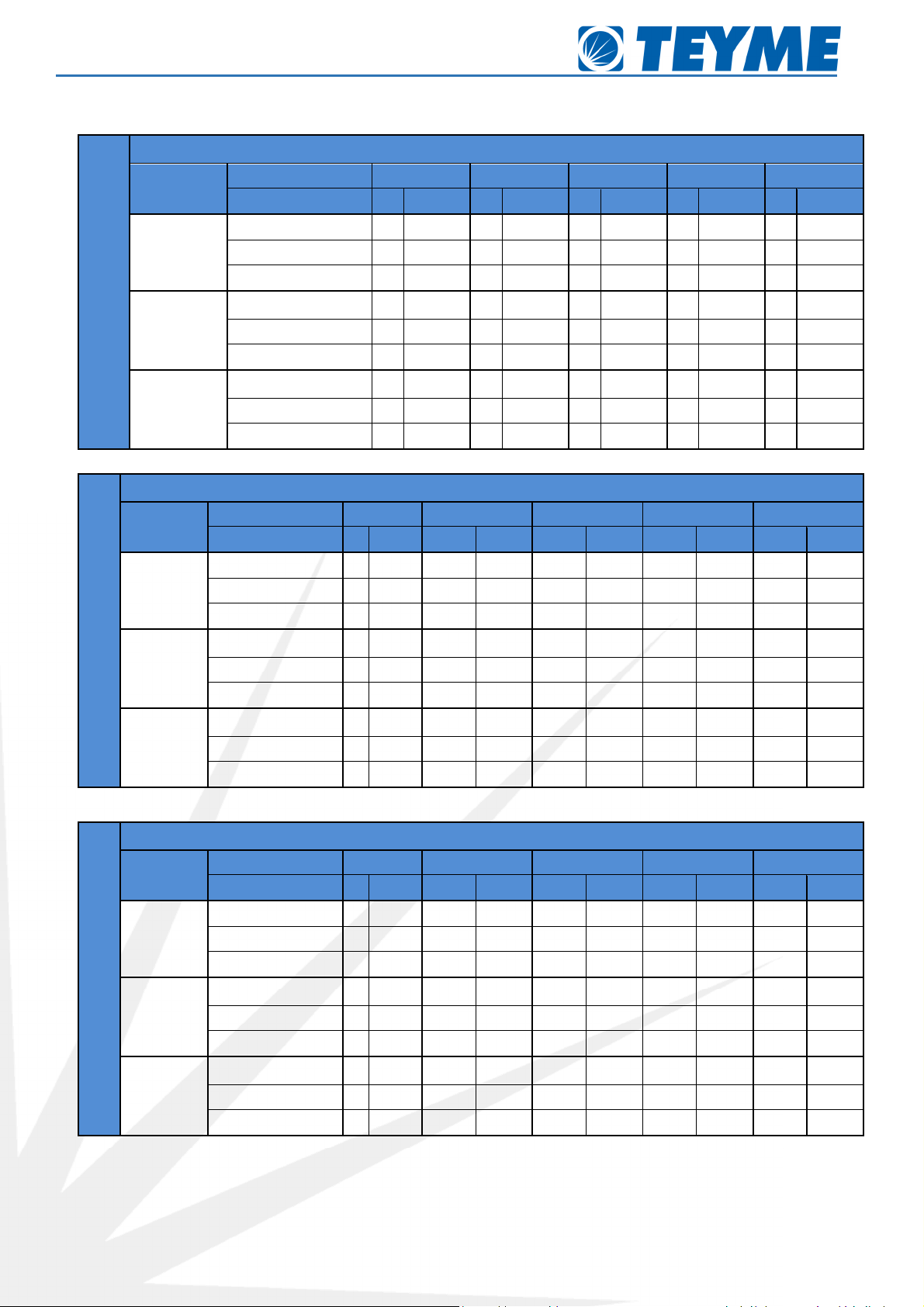
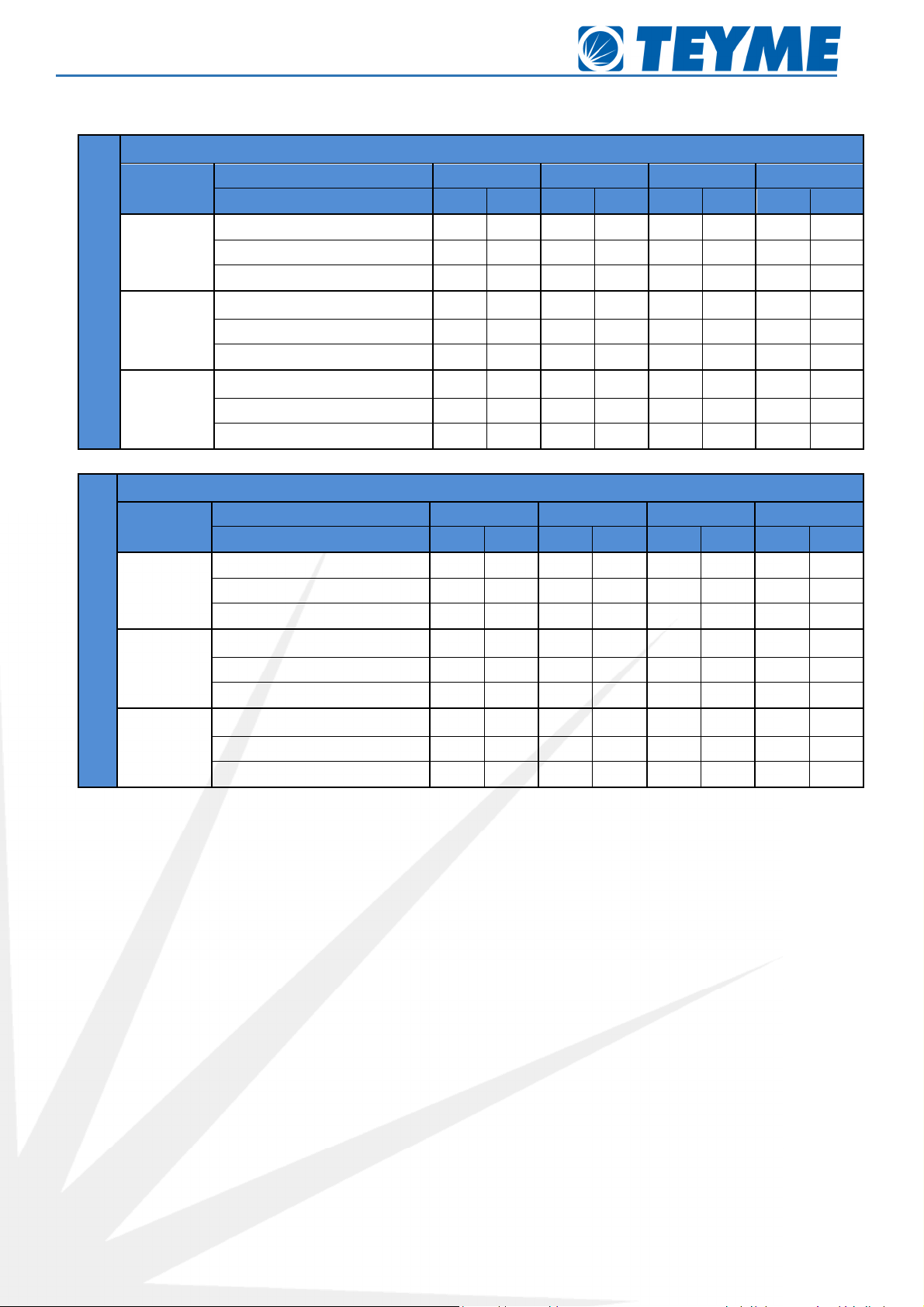
4.3.3. Air Flow of the Units
The following boards show the performances of the different air units, depending on the chosen turning speed of the PTO,
ratio of the gearbox and inclination of the impeller blades.
GTA6 UNIT
BOARD OF PERFORMANCES AIR UNIT – DYNAMIC TESTS +/- 5%
P.T.O. (rpm)
Impeller Position 1 2 3 4 5
Gear Box Speed I II I II I II I II I II
400
Flow rate (cfm) --- --- --- 10.300 --- 12,507 --- 14.714 --- 17.069
Speed (mph) --- -- --- 48,09 -- 59.28 --- 69.35 --- 80.53
Power (HP) --- --- --- 2,8 --- 3,7 --- 4,9 --- 6,8
480
Flow rate (cfm) --- --- --- 12.213 --- 14.862 --- 17.510 --- 20.159
Speed (mph) --- --- --- 57,04 --- 69,35 --- 82,77 --- 95,07
Power (HP) --- --- --- 3,9 --- 5,2 --- 7,8 --- 11,0
540
Flow rate (cfm) --- --- --- 13.537 --- 16.480 --- 19.423 --- 22.366
Speed (mph) --- --- --- 63,75 --- 77,17 --- 91,71 --- 105,14
Power (HP) --- --- --- 5,5 --- 7,7 --- 11,6 --- 17,0
Mistblowers Notice of Instructions
Page 18 of 43
GTAV6 UNIT
BOARD OF PERFORMANCES AIR UNIT – DYNAMIC TESTS +/- 5%
P.T.O. (rpm)
Impeller Position 1 2 3 4 5
Gear Box Speed I II I II I II I II I II
400
Flow rate (cfm) --- --- --- 10.300 --- 12,507 --- 14.714 --- 17.069
Speed (mph) --- -- --- 36,91 -- 44,74 --- 52,57 --- 60,40
Power (HP) --- --- --- 2,8 --- 3,7 --- 4,9 --- 6,8
480
Flow rate (cfm) --- --- --- 12.213 --- 14.862 --- 17.510 --- 20.159
Speed (mph) --- --- --- 43,62 --- 52,57 --- 62.63 --- 71.58
Power (HP) --- --- --- 3,9 --- 5,2 --- 7,8 --- 11,0
540
Flow rate (cfm) --- --- --- 13.537 --- 16.480 --- 19.423 --- 22.366
Speed (mph) --- --- --- 48,09 --- 58,16 --- 69,35 --- 79,41
Power (HP) --- --- --- 5,5 --- 7,7 --- 11,6 --- 17,0
GTA7 UNIT
BOARD OF PERFORMANCES AIR UNIT – DYNAMIC TESTS +/- 5%
P.T.O. (rpm)
Impeller Position 1 2 3 4 5
Gear Box Speed I II I II I II I II I II
400
Flow rate (cfm) ---
--- 11.477 13.537 14.126 16.480 16.627 19.423 18.982
22.072
Speed (mph) ---
--- 38,03 44,74 46,98 54,81 54,81 64,87 62,63 72,70
Power (HP) ---
--- 2,3 3,2 3,0 4,5 4,3 7,1 6,7 10,2
480
Flow rate (cfm) ---
--- 13.684 16.039 16.627 19.423 19.570 23.102 22.366
26.339
Speed (mph) ---
--- 45.86 53.69 54.81 64.87 64.87 77,17 73,82 87,24
Power (HP) ---
--- 3,8 5,2 5,0 7,5 7,2 12 10,5 16,6
540
Flow rate (cfm) ---
--- 15.303 17.804 18.684 21.777 21.924 25.603 25.014
29.135
Speed (mph) ---
--- 50,33 59,28 61,52 72,70 72,70 85 82,77 97,31
Power (HP) ---
--- 5,3 7,2 7,0 10,4 10,2 16,8 14,5 22,5
GTA8 UNIT
BOARD OF PERFORMANCES AIR UNIT – DYNAMIC TESTS +/- 5%
P.T.O. (rpm)
Impeller Position 1 2 3 4 5
Gear Box Speed I II I II I II I II I II
400
Flow rate (cfm) ---
--- 13.831 16.186 17.069 19.717 20.012 23.249 22.807
26.486
Speed (mph) ---
--- 27,96 32,44 34,67 40,26 40,26 47,20 45,86 53,69
Power (HP) ---
--- 4,0 5,9 5,5 8,1 8,0 13,1 12,0 18,3
480
Flow rate (cfm) ---
--- 16.480 19.276 20.012 23.249 23.543 27.663 26.780
31.636
Speed (mph) ---
--- 33,55 39,15 40,26 46,98 48,09 55,92 53,69 63,75
Power (HP) ---
--- 6,8 9,9 9,4 13,6 13,6 21,9 20,4 30,7
540
Flow rate (cfm) ---
--- 18.393 21.336 22.366 26.192 26.339 30.753 30.017
35.020
Speed (mph) ---
--- 36,91 43,62 44,74 52,57 53,69 62,63 60,40 71,58
Power (HP) ---
--- 9,6 14,2 13,2 19,5 19,2 31,5 28,8 44,1
Mistblowers Notice of Instructions
Page 19 of 43
GTA9 UNIT
BOARD OF PERFORMANCES AIR UNIT – DYNAMIC TESTS +/- 5%
P.T.O. (rpm)
Impeller Position 1 2 3 4
Gear Box Speed I II I II I II I II
400
Flow rate (cfm) 1 .069 20.453 21.483 25.603 25. 50 30.606 29.429 35.16
Speed (mph) 2 ,96 33,55 35, 9 42,50 42,50 51,45 49,21 59,28
Power (HP) 5 ,8 9,1 14,9 13 22,5 19,8 33,2
480
Flow rate (cfm) 20.159 24.426 25.603 30.606 30.606 36.492 34.8 3 41.348
Speed (mph) 33,55 40,26 42,50 51,45 51,45 61,52 58,16 69,35
Power (HP) 8,5 13,2 15, 25, 24 38,8 36,8 59,2
540
Flow rate (cfm) 22.660 26.633 28.546 33.255 33.990 40.31 38.552 45. 62
Speed (mph) 38,03 44, 4 48,09 55,92 5 ,04 6 ,11 64,8 6,06
Power (HP) 12,1 1 ,8 22,5 3 33,9 56,2 50,5 9,4
GTA9C UNIT
BOARD OF PERFORMANCES AIR UNIT – DYNAMIC TESTS +/- 5%
P.T.O. (rpm)
Impeller Position 1 2 3 4
Gear Box Speed I II I II I II I II
400
Flow rate (cfm) 1 .65 20.306 21.189 24. 20 25.014 28.840 2 .954 32.0
Speed (mph) 32,44 38,03 39,15 45,86 45,86 53,69 51,45 59,28
Power (HP) 6,5 10 8,5 14 11,5 18,5 14,5 23
480
Flow rate (cfm) 20.306 23.83 24. 20 28.840 29.134 33.843 32.960 3 .963
Speed (mph) 36,91 43,62 45,86 53,69 53,69 62,63 60,40 69,90
Power (HP) 10,5 16,5 14,5 23 19,5 30,5 24 3 ,5
540
Flow rate (cfm) 22.366 26.192 2 .369 31. 83 32.0 3 .3 5 36.19 41. 89
Speed (mph) 41,38 48,09 50,33 58,16 59,28 68,23 6 ,11 ,1
Power (HP) 14,5 23 19,5 31,5 26 41,5 33,5 50,5
This manual suits for next models
10
Table of contents
Other Teyme Farm Equipment manuals


