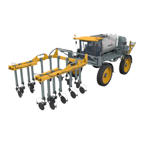
Hagie 2101 User manual

CALIFORNIA
Proposition 65 Warning
WARNING: Diesel engine exhaust and
some of its constituents are known to the
State of California to cause cancer and
birth defects or other reproductive harm.
WARNING: Battery posts, terminals, and
related accessories contain lead and lead
compounds, chemicals known to the State
of California to cause cancer and birth
defects or other reproductive harm.
ANY PICTURES CONTAINED WITHIN THIS OPERATOR’S
MANUAL THAT DEPICT SITUATIONS WITH SHIELDS, GUARDS,
RAILS, OR LIDS REMOVED ARE FOR DEMONSTRATION
PURPOSES ONLY. HAGIE MANUFACTURING COMPANY
STRONGLY URGES THE OPERATOR TO KEEP ALL SHIELDS
AND SAFETY DEVICES IN PLACE AT ALL TIMES.

01-04 493305
COVERS MACHINE SERIAL NUMBERS:U1460440001 thru U1460440200
HAGIE MANUFACTURING
COMPANY
BOX 273 CLARION, IOWA 50525 (515) 532-2861
OPERATOR’S MANUAL SUPPLEMENT FOR
HAGIE MODEL 2101
SPRAYER/DETASSELER

ABBREVIATIONS
A/C................................................AIR CONDITIONING
ADJ .................................................................. ADJUST
ADPTR.......................................................... ADAPTER
ALT......................................................... ALTERNATOR
AMP ................................................................AMPERE
APPROX .......................................... APPROXIMATELY
ASSY...........................................................ASSEMBLY
AUX..............................................................AUXILIARY
BRKT............................................................. BRACKET
BTTRY ...........................................................BATTERY
C......................................................................CELSIUS
CCA........................................COLD CRANKING AMPS
CTRL.............................................................CONTROL
CYL..............................................................CYLINDER
DIAG ..............................................................DIAGRAM
DIM.............................................................DIMENSION
DISPL..................................................DISPLACEMENT
EA ........................................................................ EACH
ELECT...........................................................ELECTRIC
F...............................................................FAHRENHEIT
FIG....................................................................FIGURE
FLO......................................................................FLOW
FRT....................................................................FRONT
FT.........................................................FOOT OR FEET
GA..................................................................... GAUGE
GAL..................................................................GALLON
HAL...............................................................HALOGEN
HR........................................................................HOUR
HYD............................................................HYDRAULIC
HYDRO .................................................HYDROSTATIC
ID.....................................................INSIDE DIAMETER
IN........................................................................... INCH
INFO...................................................... INFORMATION
Km/H....................................KILOMETERS PER HOUR
LB...................................................................... POUND
LS.........................................................LIGHT SENSOR
MAINT.................................................. MAINTENANCE
MIN....................................................................MINUTE
M/F............................................................MAINFRAME
MPH.................................................MILES PER HOUR
MT..................................................................... MOUNT
MTH.................................................................. MONTH
MTR..................................................................MOTOR
NO...................................................................NUMBER
OD............................................... OUTSIDE DIAMETER
PLT .....................................................................PLATE
PRESS........................................................PRESSURE
PRKNG .......................................................... PARKING
PSI.................................POUNDS PER SQUARE INCH
QT......................................................................QUART
RAD .............................................................RADIATOR
REC ...................................................RECOMMENDED
REQ.............................................................REQUIRED
RPM...............................REVOLUTIONS PER MINUTE
SAE...............SOCIETY of AUTOMOTIVE ENGINEERS
SEC.................................................................SECOND
SERV ..............................................................SERVICE
SLCTR ........................................................ SELECTOR
SMV......................................SLOW MOVING VEHICLE
SOLE ...........................................................SOLENOID
SPEC .................................................. SPECIFICATION
STRG...........................................................STEERING
SQ................................................................... SQUARE
TACH.....................................................TACHOMETER
TEMP...................................................TEMPERATURE
TERM........................................................... TERMINAL
TRD.................................................................... TREAD
TT............................................................... TUBE-TYPE
TU................................................................TUBELESS
VAR...............................................................VARIABLE
V............................................................................VOLT
VLV.....................................................................VALVE
W......................................................................WEIGHT
WD.........................................................WHEEL DRIVE
W/..........................................................................WITH
W/O................................................................WITHOUT
WHL...................................................................WHEEL
WK.......................................................................WEEK
WLD...........................................................WELDMENT

1
TO THE OWNER
Congratulations on your selection of a Hagie Model 2101 SPRAYER/DETASSELER.
This operator’s manual supplement is not intended to stand alone as an operating manual for
the 2101 SPRAYER/DETASSELER, but is considered an additional support publication for
your 2101 Operator’s Manual to encompass the detasseling options. We recommend that
you study your 2101 Operator’s Manual along with this supplement and become acquainted
with the adjustments and operating procedures before attempting to operate your new
sprayer/detasseler. As with any piece of equipment, certain operating procedures, service,
and maintenance are required to keep it in top running condition.
We have attempted herein to cover all of the adjustments required to fit varying
conditions. However, there may be times when special care must be considered.
Hagie Manufacturing Company reserves the right to make changes in the design and
material of any subsequent sprayer/detasseler without obligation to existing units.
We thank you for choosing a Hagie SPRAYER/DETASSELER and assure you of our
continued interest in its satisfactory operation for you. If we might be of assistance to you,
please call us. We are proud to have you as a customer.
AWORD FROM HAGIE MANUFACTURING COMPANY
Read this manual before operating.

2
The following pages and illustrations will help
you operate and service your new sprayer/
detasseler. It is the responsibility of the user to
read the Operator’s Manual and comply with the
safe correct operating procedures and lubricate
and maintain the product according to the
maintenance schedule.
The user is responsible for inspecting the
machine and having parts repaired or replaced
when continued use of the product causes damage
or excessive wear to other parts.
Keep this manual in a convenient place for
easy reference when problems arise. This manual
is considered a permanent fixture with this
machine. In the event of resale, this manual should
accompany the sprayer/detasseler. If you do not
understand any part of the manual or require
additional information or service, contact the Hagie
Customer Support Department:
Hagie Manufacturing Company
Box 273, Clarion, IA 50525
(515) 532-2861
TO THE OPERATOR
The following symbols, found throughout this manual, alert you to potentially dangerous conditions to
the operator, service personnel, or the equipment.
This symbol indicates an immanently hazardous situation
which, if not avoided, will result in death or serious
injury
.
This
symbol indicates a potentially hazardous situation
which, if not avoided, could result in death or injury.
This symbol indicates a potentially hazardous situation
which, if not avoided, may result in minor or moderate
injury. It may also be used to alert against unsafe
practices.

I. SAFETY/DECALS.............................................................................................................4-6
II. SPECIFICATIONS................................................................................................................ 7
III. PREPARING TO OPERATE ..........................................................................................8-24
IV. OPERATING INFORMATION ...................................................................................25-40
V. SERVICE AND MAINTENANCE ..............................................................................41-44
VI. TROUBLE SHOOTING ................................................................................................45-54
VII. LIMITED WARRANTY ..................................................................................................... 55
INDEX .................................................................................................................................. 57
TABLE OF CONTENTS
3

Most accidents occur as the result of failure to
follow simple and fundamental safety rules. For this
reason, most accidents can be prevented by
recognizing the real cause and doing something
about it before the accident occurs.
Many conditions cannot be completely
safeguarded against without interfering with
efficient operation and/or reasonable accessibility.
Therefore, you must study your 2101 Operator’s
Manual along with this supplementary manual and
4
I. SAFETY/DECALS
SAFETY PRECAUTIONS
learn how to use the sprayer/detasseler controls
for safe operation. Likewise, do not let anyone
operate without instruction.
Do not make modifications such as
weldments, add-ons, adaptations, or changes from
the original design of the sprayer/detasseler. Such
changes and/or modifications may become safety
hazards to you and others and WILL VOID ALL
WARRANTIES.
SAFETY
GENERAL OPERATION SAFETY
• If equipped with light sensing depth units, do not look directly into light beam. It emits a very
low intensity microwave signal which may cause possible eye damage.
• Never allow walking personnel in the same field as a detasseler.

DECAL LOCATION
5
DECALS CONTINUED
2 on each cutter housing.
650819
!
DANGER
KEEPAWAY;
CUTTING
BLADES
!
Decals warning you of avoidable danger are
located on various parts of the sprayer/detasseler.
They are there for your personal safety and
protection. DO NOT remove them. They will
fracture upon attempted removal and therefore
must be replaced.
Following are locations of important safety
decals not shown in your 2101 Operator’s Manual.
WARNING DECALS
Replace them if they are torn or missing. All
warning decals and other instructional Hagie
decals or machine striping may be purchased
through the Hagie Customer Support Department.
To replace decals, be sure that the installation area
is clean and dry; decide on exact position before
you remove the backing paper.
I. SAFETY/DECALS
CUTTING BLADES MUST OPERATE
IN CORRECT DIRECTION
BLADE ROTATION
LEFT OF OPERATOR BLADE ROTATION
RIGHT OF OPERATOR
FRONT
!
650303
Front window of cab.

650820
CAUTION
Quad puller head.
I. SAFETY/DECALS
6
650820
CAUTION
2 on each male corn chopper.
650955
Above motor control box on right cab glass.
CAUTION
BEFORE ENGAGING HYDRAULIC MOTORS
1. REDUCE ENGINE SPEED TO AN IDLE
2. CLEAR AREA OF UNAUTHORIZED
PERSONNEL

II. SPECIFICATIONS
7
A. Overall tractor height......................................136”
B. Lift arm range................................................53.0”
C. Static loaded hub height................................25.8”
D. Wheel base................................................139”
E. Combo length (w/o attachments)...............284”
F. Rear handrail height..................................124”
DETASSELER OPTION DIMENSIONS
Detasseling equipment options
Front mounted with Tasseltrol
®/LS System
Quad Puller
Number of rows available ...........4, 6, 8, 10, or 12
Drive............................................Hydraulic
Tire size ......................................4.10/3.50 2 ply
Operating speed .........................Up to 400 RPM
Pulling height ..............................Min. range – 34” to 87”
Max. range – 52” to 105”
Weight per head assembly .........86 lbs.
Cutter
Number of rows available........... 4, 6, 8, 10, or 12
Drive........................................... Hydraulic
Blade size................................... 18”
Operating speed......................... Up to 3600 RPM
Cutting height............................. Min. range – 32” to 85”
Max. range – 50” to 103”
Weight per head assembly......... 62 lbs.
Male corn equipment options
Male corn cutter (1 blade)........................................................................................Hydraulically driven 18” blade
Male corn cutter (4 blade)........................................................................................Hydraulically driven 18” blades
(includes left and right)
Male corn chopper (8 blade)....................................................................................Ground driven 15” blades or
Ground driven 20” blades
A
B
C
E
D
F

8
III. PREPARING TO OPERATE
In shipment, some of the components may
have been sent loose and need to be installed be-
fore operating. In order to ensure proper installation
of the optional attachments, refer to your HAGIE
2101 SPRAYER/DETASSELER Parts Manual for
the correct option for outlining the installation, hy-
draulic schematic, and wiring diagram. Read and
comply with the following instructions. Always
make sure you have proper equipment and help
when installing the attachments.
Converting Your Sprayer to a Detasseler
FIG 3.1

9
III. PREPARING TO OPERATE
REMOVING BOOMS CONTINUED
REMOVING SPRAY BOOMS
Park the sprayer on level ground and set the
parking brake. To prepare the booms for removal,
lift the booms out of the boom cradle, leaving the
extensions folded in. Fold them out enough to clear
the solution tanks when lowered. Lower the booms
onto heavy-duty stands, supporting them in at least
four places (fig. 3.2).
Disconnecting Attachments – All of the fol-
lowing items need to be disconnected before you
remove the booms:
• Solution supply quick-couple (fig. 3.3, item 1).
• Foamer supply quick-couples (fig. 3.3, item 2).
• Boom indicator lights wire harness (fig. 3.3, item 1).
• Boom control stack valve wire harness (fig. 3.3,
item 1).
• Raven control wire harness (fig. 3.3, item 1).
• Solution valve wire harness (fig. 3.3, item 1).
• Hydraulic quick-couplers on boom control stack
valve (fig. 3.3, item 3).
FIG 3.2
FIG 3.3
1
2
3

10
III. PREPARING TO OPERATE
REMOVING BOOMS CONTINUED
FIG 3.6
1
2
FIG 3.7
Each lift arm is secured in place with six (12 total)
heavy duty bolts (fig. 3.4). Remove each bolt from the
quick-attach mount. Remove the air control linkage (fig.
3.5, item 2) from the air valve control arm (fig. 3.5, item 1)
on each front leg assembly. Push the air valve control
arm down to release all the air out of the bag. When the
air bag has lowered, the “mounting pin” (fig. 3.6, item 2)
on each quick-attach mounting plate should drop clear of
the “mounting hook” (fig. 3.6, item 1) on each lift arm.
Once clear, back the machine away slowly (fig. 3.7).
FIG 3.4
Disconnecting Booms
FIG 3.5
1
2

1. Attach the center tool bar (fig. 3.8, item 1) and bolt it in place according to 2101 SPRAYER/
DETASSELER Parts Manual.
2. Attach left and right outriggers (fig. 3.8, item 3) with supplied hardware. Refer to 2101SPRAYER/
DETASSELER Parts Manual.
3. Attach support rods if required.
4. Attach fold cylinder mounts (fig. 3.8, item 2) on outriggers.
11
III. PREPARING TO OPERATE
ATTACHING EQUIPMENT CONTINUED
FIG 3.8
1
2
3
ATTACHING DETASSELING EQUIPMENT

12
III. PREPARING TO OPERATE
Attach Outrigger Fold Stack Valve – Attach the outrigger hydraulic fold stack valve (fig. 3.9, item 1) in
the center of the tool bar with supplied mounting bracket and hardware. Refer to 2101 SPRAYER/
DETASSELER Parts Manual for correct hardware and hydraulic schematic. Attach supplied wire harness to
boom control stack valve wire harness connection (see page 9). Refer to 2101 SPRAYER/DETASSELER
Parts Manual for correct fold stack valve wiring schematic.
Attach Outrigger Fold Cylinders – Attach the outrigger fold cylinders (fig. 3.9, item 3) with supplied
hardware according to 2101 SPRAYER/DETASSELER Parts Manual. Also refer to 2100 SPRAYER/
DETASSELER Parts Manual for correct hydraulic schematic.
Attach Lift Arm Stack Valve – Attach the hydraulic lift arm stack valve (fig. 3.9, item 2) toward the left
of the tool bar with supplied mounting bracket and hardware. Refer to 2101 SPRAYER/DETASSELER
Parts Manual for correct hardware and hydraulic schematic. Attach supplied wire harness(es) to “jumper”
panel (see page 22). Refer to 21001SPRAYER/DETASSELER Parts Manual for correct lift stack valve wir-
ing schematic.
ATTACHING EQUIPMENT CONTINUED
FIG 3.9
1
2
3

Attaching Lift Assemblies
Refer to 2101 SPRAYER/DETASSELER Parts
Manual for correct hardware when following these
steps:
1. Attach the lift mounts (fig. 3.10, item 2) to the
tool bar and outriggers at the appropriate spac-
ings.
2. Attach the lift arms (fig. 3.10, item 1) to the lift
mounts.
3. Attach the lift arm cylinders to the lift arm as-
semblies (fig. 3.11, item 2).
4. Attach the tool bar weldment to the lift arm as-
semblies (fig. 3.11, item 1).
5. Connect hydraulic hoses to lift cylinders. Refer
to 2101 SPRAYER/DETASSELER Parts Man-
ual for correct hydraulic schematics.
III. PREPARING TO OPERATE
ATTACHING EQUIPMENT CONTINUED
13
FIG 3.11
1
2
FIG 3.10
1
2

14
III. PREPARING TO OPERATE
3.12, item 2) to the lift arm stack valve filtered con-
nection (fig. 3.12, item 1). Connect the hydraulic
return quick-couple to the lift arm stack valve (fig.
3.12, item 4).
ATTACHING EQUIPMENT CONTINUED
FIG 3.12
4
1
2
3
Connecting Fold and Lift Hydraulics
Connect the hydraulic supply quick-couple to
the filtered connection on the outrigger fold stack
valve (fig. 3.12, item 3). With the supplied hardware
(refer to 2101 SPRAYER/DETASSELER Parts
Manual), connect the outrigger fold stack valve (fig.

15
III. PREPARING TO OPERATE
ATTACHING QUAD PULLERS
1. Attach the quad pullers to each lift arm tool bar (fig. 3.13).
2. Install the stalk guides to the quad puller head assembly
(fig. 3.14, item 3).
3. Attach the deflector shield mount tube (fig. 3.14, item 1)
and the deflector shields for right or left hand deflection (fig.
3.14, item 2).
4. Refer to page 16 for information about installing hydraulic
hoses.
5. Normal operating angle of the quad puller is obtained when
the tool bar mount surface is parallel to the ground (fig.
3.15, item 1). This angle can be varied by an adjusting bolt
(fig. 3.15, item 2) and slot (fig. 3.15, item 3).
6. Adjust tire pressure to approximately 10 pounds.
NOTE:
Be sure all four tires have equal
pressure. Check tire pressure daily.
NOTE:
Some quad pullers may come pre-assembled to the tool b
ar. In this case, you would attach them to the lift assembly.
FIG 3.15
1
2
3
FIG 3.13
FIG 3.14
1
2
3

16
III. PREPARING TO OPERATE
ATTACHING QUAD PULLERS CONTINUED
Quad Puller Hydraulic As-
sembly
Hydraulic hoses on Quad Puller
heads should be hooked up so tires ro-
tate according to figure 3.16 and figure
3.17. Refer to 2101 SPRAYER/
DETASSELER Parts Manual for correct
hardware, hose lengths, and hydraulic
schematic.
FIG 3.17
rotation
rotation
rotation
front
front
THREE-HEAD SERIES
FIG 3.16
front
rotation
rotation
TWO-HEAD SERIES

17
III. PREPARING TO OPERATE
ATTACHING CUTTER HEADS
1. Attach the cutter head assembly to the tool bar
(fig. 3.18).
2. Install the stalk guides to the cutter head assem-
bly (fig. 3.20, item 1).
3. Refer to pages 18-19 for information about in-
stalling hydraulic hoses.
NOTE:
Some cutters may come pre-assembled to
the tool bar. In this case, you would attach
the assembly to the lift assembly.
4. Adjust the cutter heads using the adjusting bolts
so the front of the cutter head is pointing down-
ward approximately ½ inch (fig. 3.20).
FIG 3.19
CUTTING BLADES MUST OPERATE
IN CORRECT DIRECTION
BLADE ROTATION
LEFT OF OPERATOR BLADE ROTATION
RIGHT OF OPERATOR
FRONT
!
Make sure the cutter blades operate
in the correct direction (fig. 3.19).
FIG 3.20
1
1
A – B must
equal ½ inch
A
B
LEVEL
GROUND
FIG 3.18
ATTACHING CUTTERS CONTINUED
Table of contents
Other Hagie Farm Equipment manuals

Hagie
Hagie DTS 10 User manual

Hagie
Hagie 204 User manual

Hagie
Hagie DTS 10 User manual

Hagie
Hagie DTS 8 HI-TRACTOR User manual

Hagie
Hagie NTB Series User manual

Hagie
Hagie DTB User manual

Hagie
Hagie 204SP User manual

Hagie
Hagie NTB Series User manual

Hagie
Hagie 204 User manual

Hagie
Hagie NTB 16-Row User manual
Popular Farm Equipment manuals by other brands

VOSS.farming
VOSS.farming profiCUT go instruction manual

Horizont
Horizont Ranger B4 instruction manual

Kellfri
Kellfri 35-HKK operating instructions

GREAT PLAINS
GREAT PLAINS Yield-Pro 3P3025AH manual

sitrex
sitrex SB150 Assembly, use and maintenance

Galebreaker
Galebreaker Bayscreen Installation and operating instructions