TGS DIANA Series User manual
22-INCH INDOOR CEILING FAN
DIANA™
INSTALLATION INSTRUCTIONS
www.trulygreensolutions.com

Table of Contents ................................................................ 2
Safety Information............................................................... 2
Warranty ............................................................................... 3
Pre-Installation .................................................................... 3
Installation............................................................................ 6
Assembly............................................................................ 7
Operation ........................................................................... 15
Care and Cleaning.............................................................15
Troubleshooting................................................................. 16
To reduce the risk of electric shock, ensure the electricity has
been turned off at the circuit breaker or fuse box before you
begin.
All wiring must be in accordance with the National Electrical
Code ANSI/NFPA 70 and local electrical codes. Electrical
electrician.
The outlet box and support structure must be securely mounted
and capable of reliably supporting 15.9 kg (35 lbs) Use only UL-
listed outlet boxes marked “Acceptable for Fan Support of 15.9
kg (35 lbs) or less.”
Do not place objects in the path of the blades.
Safety Information
Table of Contents
READ AND SAVE THESE INSTRUCTIONS.
installation should be performed bya qualified licensed
IC Statement ...................................................................... 17
WARNING: To reduce the risk of personal injury, do not
WARNING:
WARNING: To avoid possible electrical shock,
turn the electricity off at the main fuse box before
wiring. If you feel you do not have enough electrical
wiring knowledge or experience, contact a licensed
electrician.
CAUTION: To reduce the risk of personal injury,
use only the screws provided with the outlet box.
CAUTION: To avoid personal injury or damage to the fan
and other items, use caution when working around or
cleaning the fan.
bend the blade brackets when installing the brackets,
balancing the blades, or cleaning the fan. Do not insert
foreign objects in between rotating fan blades.
To reduce the risk of fire, electric shock
or personal injury, mount to an outlet box marked
“acceptable for fan support of 15.9 kg (35 lbs)
or less” and use screws provided with the outlet box.
Thefan must bemounted with a minimumCAUTION:
of 7 ft. (2.1m) of clearance from the trailing edge of the
blades to the oor.
After making electrical connections, spliced conductors
should be turned upward and pushed carefully up into the
outlet box. The wires should be spread apart with the
grounded conductor and the equipment-grounding conductor
on one side of the outlet box and ungrounded conductor on
the other side of the outlet box.
All set screws must be checked and retightened where
necessary before installation.
Changes or modifications not expresslyCAUTION:
approved by the party responsible for compliance could
void the user’s authority to operate the equipment.
WARNING:
shock, do not use this fan with any solid-state speed
control device.
To reduce the risk of re or electric
□
□
□
□
□
□
2
www.trulygreensolutions.com

Pre-Installation
Warranty
TOOLS REQUIRED
NOTE: These are approximate measures. They do not
include the amps and wattage used by the light kit.
Phillips
screwdriver
Flat head
screwdriver
Adjustable
wrench
Electrical
tape
Wire
cutter
Step ladder
SPECIFICATIONS
29.7
30.5
30.5
950
825
610
VoltsSpeedSize CFM
Fan Power
Consumption
(Without Lights)
WATT
(Higher Is Better)
CFM/WATT
Net
Weight
Gross
Weight Cubic Feet
22 in.
Low
120
20
5.23 cu. ft.
Medium 27
High 32
23.81 lbs
(10.8 kgs)
30.82 lbs
(13.98 kgs)
3
www.trulygreensolutions.com
must be paid by the customer.
province to province. This warranty supersedes all prior warranties. Shipping costs for any return of the product as part of a
claim on the warranty
exclusion or limitation may not apply to you. This warranty gives specific legal rights, and you may also have other rights which vary from
may otherwise be accorded by law. Some provinces do not allow the exclusion of incidental or consequential damages, so the above
not be liable for incidental, consequential, or special damages arising out of or in connection with product use or performance except as
Some provinces do not allow limitation on how long an implied warranty lasts, so the above limitation may not apply to you. The
retailer shall
limited to the time period as specified in the express
warranty.
ability and fitness for a particular purpose to the extent
permitted by
law. The duration of any implied warranty which cannot be disclaimed is
warranty invalid. There is no other express warranty. We hereby disclaim
any and all warranties, including but not limited to those of
merchant
certain amount of “wobble” is normal and should not be considered a defect.Servicing performed by unauthorized persons shall render the
pitting, corroding, tarnishing or peeling. Brass finishes of this type give their longest useful life when protected from varying weather conditions. A
covered by this warranty. Because of varying climatic conditions, this warranty does not cover any changes in brass finish, including rusting,
product are your responsibility. Damage to any part such as by accident, misuse, improper installation, or by affixing any accessories, is not
returned. To obtain warranty service, you must present a copy of the receipt as proof of purchase. All costs of removing and reinstalling the
original purchaser. We agree to correct such defects without charge or at our option replace with a comparable or superior model if the product is
free from defects in workmanship and material at the time of shipment from the factory for a period of one year after the date of purchase by the
lifetime after the date of purchase by the original purchaser. We also warrant that all other fan parts, excluding any glass or acrylicblades, to be
We warrant the fan motor to be free from defects in workmanship and material present at time of shipment from the factory for a
period of a

Pre-Installation (continued)
HARDWARE INCLUDED
: Hardware not shown to actual size.
AA
BB
CC
DD
GG
Canopy screw (not to scale) (preassembled) 2
Wire nuts (not to scale) 10
1
1
Hitch pin (not to scale) (preassembled)
5
AA
BB
CC
DD
EE
Part Description Quantity
Lock pin (not to scale) (preassembled)
NOTE
FF
GG
EE 2
Set screw (not to scale) (preassembled)
FF 5
Wood screw (not to scale)
4
www.trulygreensolutions.com
Metal washer (not to scale)
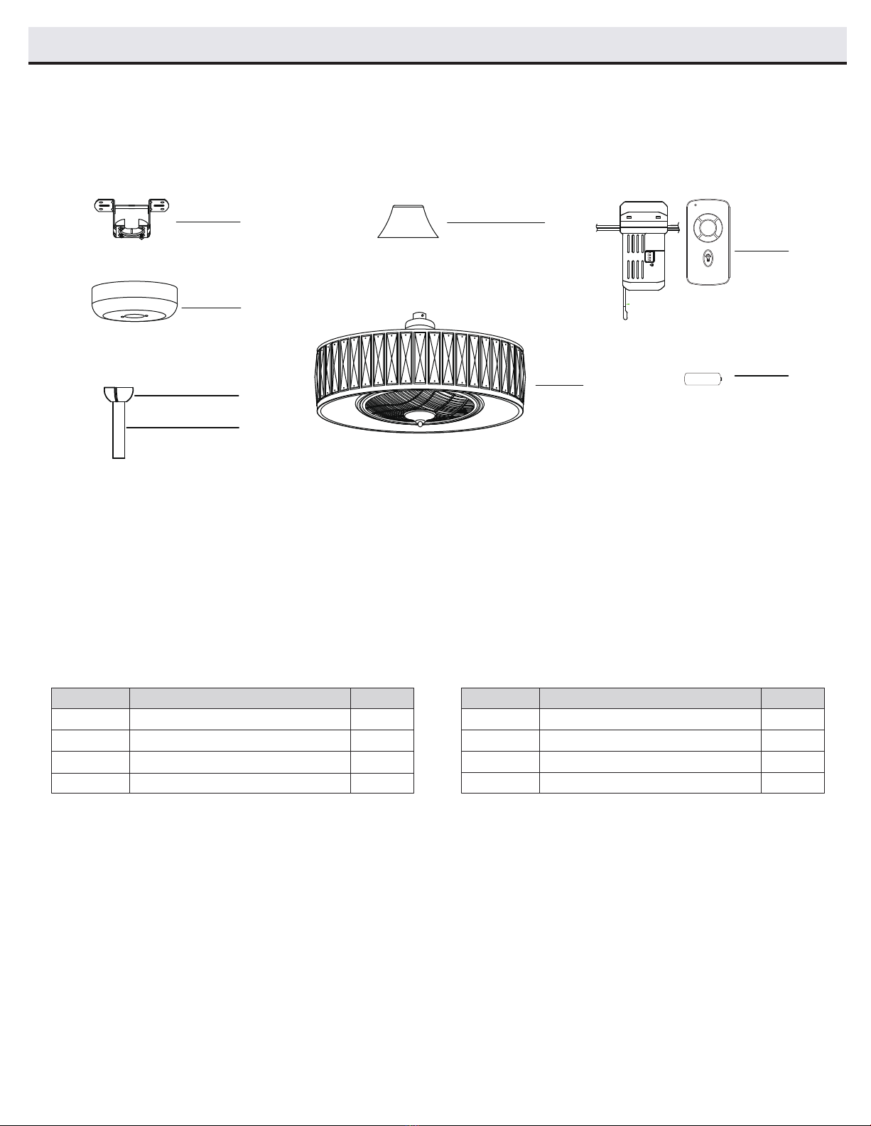
PACKAGE CONTENTS
D
E
Hanger ball (preassembled)
Downrod 6” and 18” 2
1
A
B
C
1
1
1
Mounting bracket
Canopy Fan motor assembly
Remote control set
1
Coupling cover
G
1
F
E
D
C
B
A
G
Part Description Quantity Part Description Quantity
Pre-Installation (continued)
F
ON
12V
1 2 3 4
ON DIP
H
1
Battery 23A 12V
H
2
0
3
1
5
www.trulygreensolutions.com

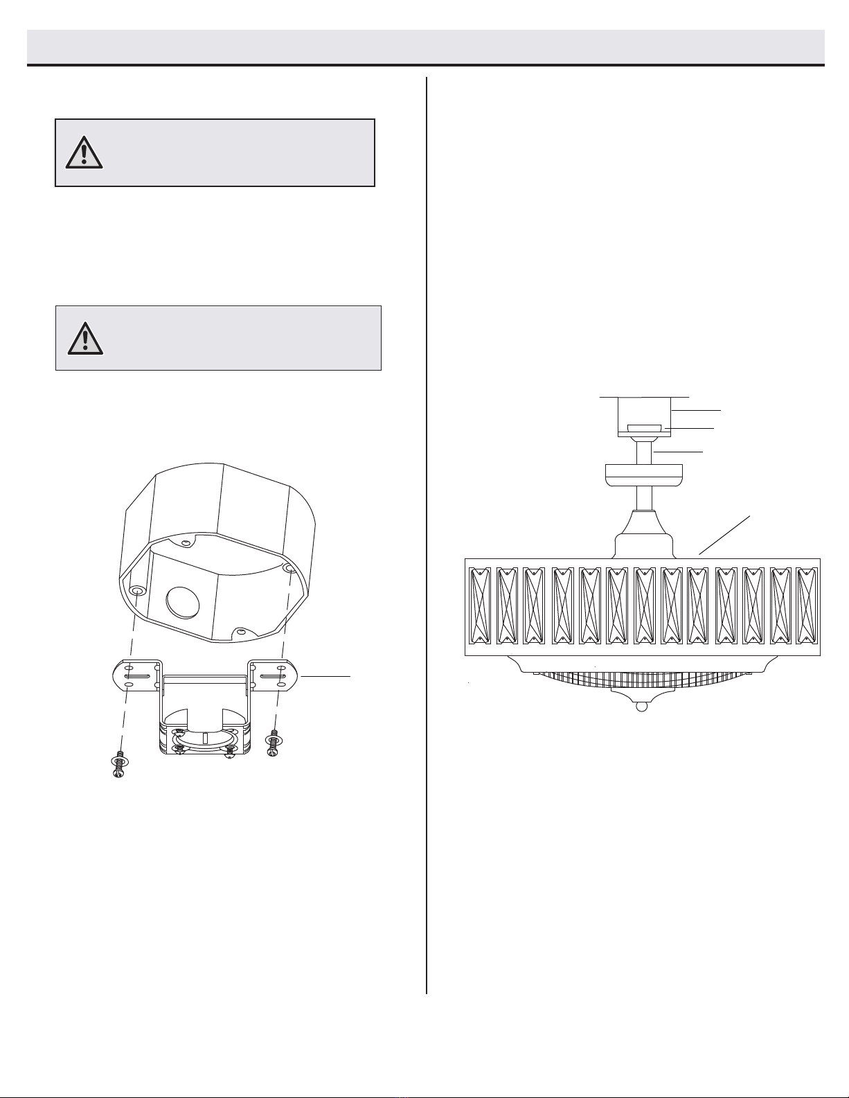
Installation
MOUNTING OPTIONS
WARNING:
personal injury, mounttooutletbox marked “acceptable
for fan support of 15.9 kg (35lbs) or less” using the
screwsprovided with theoutlet box. An outlet box
not beacceptable for fan support and may need to be
If your ceiling fan does not have an existing UL-listed mounting
box, then install one using the following instructions:
□Disconnect the power by removing the fuses or turning off
the circuit breakers.
□Secure the outlet box directly to the building structure.
Use the appropriate fasteners and materials. The outlet box
and its bracing must be able to fully support the weight
of the moving fan (at least 15.9 kg). Do not use a plastic
outlet box.
The illustrations below show two different ways to mount the
outlet box.
you may need an installation hanger bar as shown above.
NOTE: You may need a longer downrod to maintain
proper blade clearance when installing on a steep, sloped
ceiling. The maximum angle allowable is 10° away from
horizontal.
Outlet Box
Outlet Box
Outlet Box
Hanger Bar
To reduce the risk of fire, electric shock, or
commonly used for the support of lighting xtures may
replaced. If in doubt, consult a qualied electrician.
To hang your fan where there is an existing xture but no ceiling joist,
6
www.trulygreensolutions.com

Assembly - Standard Ceiling Mount
Assembling the fanRouting the wires
Route the wires exiting the top of the fan motor
assembly (F) into the coupling cover (E).
Make sure the slot openings are on top. Route the
wires through the canopy (B) and then through the
downrod (D) assembly.
21
□
□
□
CAUTION: To ensure wobble-free operation and to avoid
damage to the fan, the downrod (D) and the set screw
(EE) must be completely tightened.
B
E
D
F
Loosen the set screws (EE) in the downrod coupler until the
inside of the channel is clear of the screw tip.
Remove and save the lock pin (DD) on
the end of the downrod (D).
Slide the ceiling canopy (B)onto the downrod (D), followed by the
coupling cover (E).
Attach the downrod (D) into the coupler until the lock pin (DD) can
be inserted through the hole in both the rod and coupler.
Tighten both set screws (EE) on the coupler.
Insert the lock pin (DD) through the hole in the
coupler and
downrod (D), and then attach the hitch pin (CC) on the other side.
□
□
□
Make sure power is off before attempting
installation.
□
□
CC
DD
EE
D
E
B
WARNING:
7
www.trulygreensolutions.com
Assembly - Standard Ceiling Mount (continued)
Attaching the fan to the electrical box
3Hanging the fan
□Carefully lift the fan motor assembly (F) up to the mounting
bracket (A).
□Seat the hanger ball (C) portion of the downrod assembly (D)
in the mounting bracket (A) socket. Ensure that the tab on the
mounting bracket (A) socket is properly seated in the groove
in the hanger ball.
4
□Pass the 120V supply wires through the center hole in the
mounting bracket (A).
□
□
WARNING:
To reduce the risk of fire, electric shock
or personal injury, mount to outlet box marked
“acceptable for fan support of 15.9 kg (35 lbs)
or less” and use screws provided with the outlet box.
A
Securely tighten the two outlet box screws.
Install the ceiling mounting bracket (A) on the outlet box using the
two mounting screws provided with the outlet box. If necessary,
use leveling washers (not included) between the mounting
bracket (A) and outlet box.
A
D
F
C
NOTE:
The flat side of the mounting bracket (A) is toward
the outlet box. When it is used as a flush mount, it is
important that the mounting bracket (A) be level.
8
www.trulygreensolutions.com

Assembly - Standard Ceiling Mount (continued)
Making the electrical connections
5
WARNING:
WARNING:
Follow the steps below to connect the fan to your house
supply wires. Secure the wire nuts (BB) supplied with your
fan by wrapping the connections with electrical tape.
the electricity is turned off at the circuit breaker or main
fuse box before wiring.
To avoid possible electrical shock, ensure
including the ground, and that no bare wire is visible at
the wire nuts, except for the ground wire.
Check to see that all connections are tight,
Secure the wire connections with plastic wire nuts
(BB) provided with the electrical hardware.
Insert the receiver into the mounting bracket with
the at side of the receiver facing the ceiling.
Connect the ground conductor of the 120V supply
(this may be a bare wire or a wire with green-colored
insulation) to the green ground lead(s) of the fan.
There are two green grounding leads: one from the
mounting bracket and one from the hanger ball/
downrod (D) assembly.
BB (X7)
Put the end of the cable through the holes of the crimping column
and form a small loop of suitable size. Then tighten the crimping
screws to lock the cable. Use a wood screw (FF) with a metal
washer (GG) through the cable loop and secure it at the ceiling.
□
□
□
□
□
Connect the black (live) wire from the ceiling fan to the black
wire “MOTOR L” from the receiving unit.
Connect the white (neutral) wire from the ceiling fan to
the white wire “MOTOR N” from receiving unit.
Connect the blue wire from the ceiling fan to the blue wire
“LIGHT +” from the receiving unit.
Connect the black (live) wire from the power supply to the
black wire “AC in L” from the receiving unit.
Connect the white (neutral) wire from the power supply to the
white wire “AC in N” from the receiving unit.
□
□
□
D
ATTENTION: This steel cable is a protection device to
prevent people being hurt in case the xture drops
accidentally. It must be securely installed.
GG
FF
□
□
Connect the orange wire from the ceiling fan to the orange
wire “LIGHT -” from the receiving unit.
□
9
www.trulygreensolutions.com
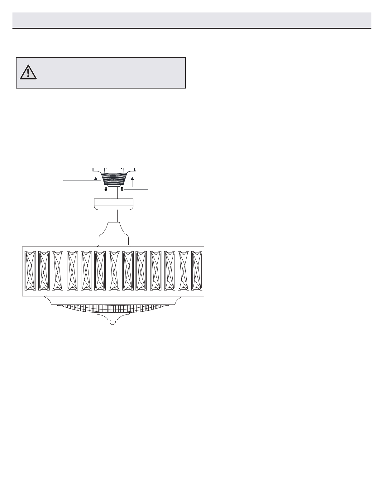
Assembly - Standard Ceiling Mount (continued)
Mounting the fan
6
WARNING: When using the standard ball/downrod mounting, the
tab in the ring at the bottom of the mounting bracket must rest in
the groove of the hanger ball. Failure to properly seat the tab in
the groove could cause damage to the wiring.
A
AA
AA
□Align the locking slots of the ceiling canopy (B) with the two
canopy screws (AA) in the mounting bracket (A). Push up tor
engage the slots and turn clockwise to lock in place.
□Install the two canopy screws (AA) (saved from Assembly
step 1, “Preparing for mounting”) into the holes in the
canopy (B) and tighten them firmly.
B
10
www.trulygreensolutions.com
Operation
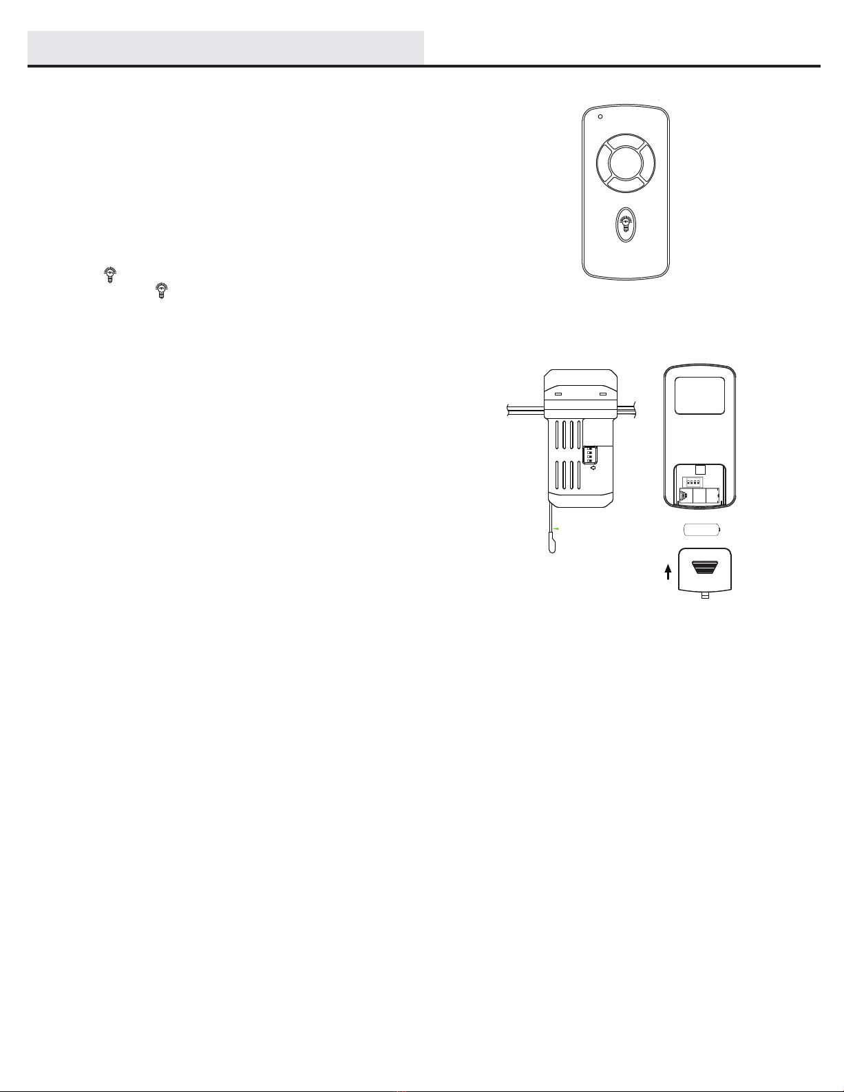
Slide the code switches on the receiver to the same
positions that are set on the remote control.
OPERATING THE REMOTE CONTROL
2
0
3
1
ON
FOOID;A25-TXOO3E
This device complies with part 15 of the FCCrules
Operation is subject to the following two
conditiones
This device complies with part 15 of the FCCrules
Operation is subject to the following two
conditiones
This device complies with part 15 of the FCCrules
Operation is subject to the following two
conditiones
12V
1 2 3 4
ON DIP
1 2 3 4
ON DIP
Remove the battery cover on the back of the remote control
and install a 12V battery. Reattach the battery cover.
□
□
□
□
□
□
Light Control
Speed Control
Press the 1, 2, or 3 button to start the fan.
Press the 0 button to stop the fan.
Press to turn the light on or off.
Press and hold to dim the light.
11
www.trulygreensolutions.com

Care and Cleaning
Troubleshooting
Problem Solution
The fan will not start. □Check the main and branch circuit fuses or breakers.
□Check the line wire connections to the fan and switch wire connections in the switch housing.
□Check the battery in the remote control.
□Ensure you are in the normal range of 10-20 feet.
□Turn the power off and ensure that the dip switch settings are the same on the remote control and receiver.
The fan is noisy. □Ensure all motor housing screws are snug.
□Ensure the screws that attach the fan blade bracket to the motor hub are tight.
□Ensure the wire nut connections are not rattling against each other or the interior wall of the switch housing.
□Allow a 24-hour “breaking in” period. Most noises associated with a new fan disappear during this time.
□If you are using the ceiling fan light kit, ensure the screws securing the glassware are tight. Check that the light
bulbs are also secure.
□Ensure the canopy is a short distance from the ceiling. It should not touch the ceiling.
□Ensure your outlet box is secure and rubber isolator pads were used between the mounting plate and outlet box.
The fan wobbles. □
□
□Becauseof thefan’s natural movement, some connections may become loose. Check the support connections, brackets, and blade
attachments twice a year. Make sure they are secure. Itisnot necessary to remove the fan from the ceiling.
□Clean your fan periodically to help maintain its new appearance over the years. Do not use water when cleaning, as thiscould damage
plating is sealed with a lacquer to minimize discoloration or tarnishing.
□You can applya light coatoffurniture polish to the wood for additional protection and enhanced beauty. Cover small scratches with a
light application ofshoe polish.
□You donotneed tooil your fan. The motor has permanently lubricated, sealed ball bearings.
WARNING: Make sure the power is off before cleaning
your fan.
the motor or wood, or possibly cause an electrical shock. Use only a soft brush or lint-free cloth to avoid scratching the nish. The
□Always unplug the fan before cleaning, disassembly or servicing.
12
www.trulygreensolutions.com
to you at no
charge.
fan continues to wobble, please contact Truly Green Solutions Customer Service. A balancing
kit will be sent
each blade to the ceiling. Any measurement deviation should be within 1/8 in. Run the fan for ten minutes. If the
ceiling. Rotate the fan until the next blade is positioned for measurement, and measure from the same point on
ceiling above the tip of one of the blades. Measure from a point on the center of the blade to the point on the
Most fan wobble problems are caused when blade levels are unequal. Check this level by selecting a point on
the
Check that all blade and blade arm screws are secure.

This device contains license-exempt transmitter(s)/receiver(s) that comply with lnnovation, Science and Economic Development Canada’s
license-exempt RSS(s). Operation is subject to the following two conditions :
□This device may not cause interference.
□This device must accept any interference, including interference that may cause undesired operation of the device.
IC Statement
13
www.trulygreensolutions.com
Table of contents
Other TGS Fan manuals


Popular Fan manuals by other brands


Swegon
Swegon ADAPT Free b Installation, commissioning maintenance

alora mood
alora mood ARCHER instruction sheet

Kichler Lighting
Kichler Lighting Tranquil instruction manual

NRD
NRD Staticmaster 4068 Installation, operation & maintenance manual

Thetford
Thetford C260 Cassette Toilet installation instructions

Caframo
Caframo 7478D operating instructions


