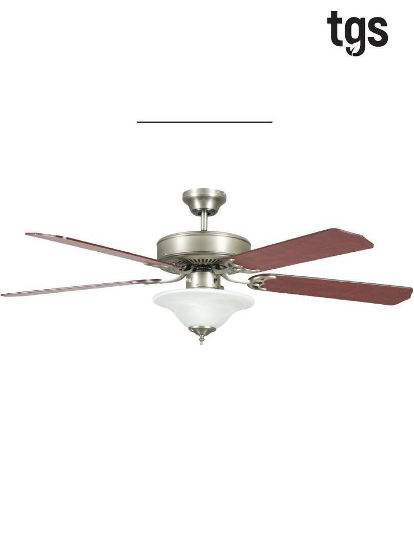
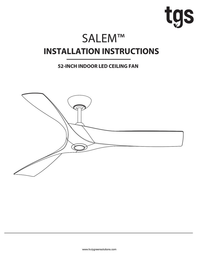
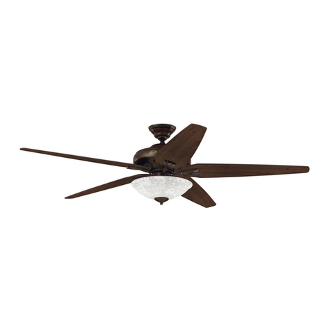
TGS BEVERLY Series User manual

BEVERLY™
INSTALLATION INSTRUCTIONS
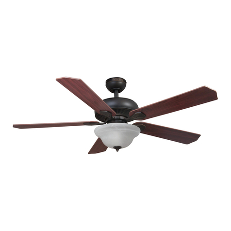
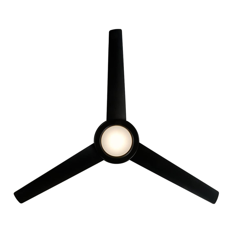
52-INCH INDOOR LED CEILING FAN
www.trulygreensolutions.com

Dimension Reference:
Hardware Package Included:
Fan Parts Included:
Hardware Package
16
16Paper Washers.
S11
S12
e1
1
3Bracket Screw.
S11.
S12
1
3. Canopy
4. Coupler Cover
6.
Blade Arm
7. Fan Blade
5
6
7
1
5. Fan Motor Assembly 1
1
1
5
5
1
2
3
4
5-1/4 in
2-1/2 in
10-3/4 in
13-1/4 in
52 in
2
www.trulygreensolutions.com

Exploded View:
Support Rod
Cotter Pin
Ceiling Canopy
Canopy Screws
Mounting Bracket
Coupler Cover
Blade Arm Screws
Blade Arm
Blade
Three Speed Switch
Pull Chain
Fan Motor
Assembly
Safety Pin
Junction Box
Switch Housing
Fiber Washer
3
www.trulygreensolutions.com

4
www.trulygreensolutions.com
supplied by the person(s) installing, caring for and operating fan.
common sense, caution and care are factors which can not be built into this product. These factors must be
are not meant to cover all possible conditions and situations that may occur. It must be understood that
•
NOTE: The safeguards provided by these safety instructions and by any separate installation instructions
necessary.
grease and permanently sealed at the factory so that, under normal conditions, further attention is not
•
Lubrication of your new ceiling fan is not necessary. The ball bearings have been adequately charged with
refer to a do-it-yourself wiring handbook or hire a qualified electrician to install your fan.
You could however, encounter situations or problems not covered in this manual. Should this occur, please
•
Every effort has been made to provide you with proper instructions for the safe installation of this ceiling fan.
finish...and will VOID YOUR WARRANTY.
high humidity. Installation in this type of location could be UNSAFE, will most likely damage the fan and its
•
This ceiling fan was not designed for installation in any location where it might be exposed to moisture or
the ceiling.
any point in its rotation and a minimum of 7 feet from blade level to floor and 10 inches from the blades to
•
The location you choose should have a minimum clearance of 20 inches from any wall to the blade tip at
necessary
products for the proper and safe installation of your ceiling fan.
hardware and do-it-yourself centers. In most cases your Truly Green Solutions dealer will have all the
Support”. If you have any questions, outlet boxes and support systems for ceiling fans are available at most
it is securely attached and able to support at least 50 pounds of moving weight marked “Acceptable for Fan
•
If you plan to use an existing electrical location check to make sure that the outlet box is not PLASTIC, that
Support”
(Plastic outlet boxes are not recommended for ceiling fan installation).
box should be able to support a minimum moving weight of 50 pounds and marked “Acceptable for Fan
electrician to run the wiring and install an outlet box designed for ceiling fans or heavy fixtures. The outlet
•
If the location where you plan to install your fan does not already have an electrical outlet, hire a licensed
amp breaker or fuse. Make sure that your electrical system and choice of location meet these requirements.
•
Basic requirements for a ceiling fan installed with lights are 120V AC-60Hz on a grounded circuit with a 15
connections. Plastic electrical tape is not recommended.
of the codes and wire the fan accordingly. Never leave bare wire uncovered, use wire nuts to cap all
•
Make sure that all wiring conforms to national and local electrical codes. If you are in question obtain a copy
installing or servicing this fixture.
•
To avoid the risk of electrical shock be sure to shut off power at the main fuse or circuit breaker box before
INSTALL
YOUR NEW CEILING FAN. SAVE INSTRUCTIONS.
ELECTRICAL WIRING PROCEDURES WE RECOMMEND THAT YOU HAVE
A
QUALIFIED ELECTRICIAN
THE FAN. IF YOU ARE NOT FAMILIAR WITH NATIONAL AND LOCAL ELECTRICAL CODES AND BASIC
READ ALL SAFETY INFORMATION AND INSTALLATION INSTRUCTIONS BEFORE YOU BEGIN INSTALLING
Safety
Instructions:

• To reduce the risk of fire, electrical shock, or personal injury, mount this fan to an outlet box marked
“Acceptable for Fan Support of 22.7 kg ( 50 lbs )” or less and use Mounting Screws provided with the outlet
box. CAUTION: Install the primary mounting means and use only the hardware provided with the fan.
• To reduce the risk of personal injury take care not to bend the blade brackets when installing the brackets,
balancing the blades or cleaning the fan. Be careful not to insert foreign objects in between rotating fan
blades.
• To reduce the risk of fire or electrical shock, do not use this fan with any solid-state speed control device.
• The important safeguards and instructions appearing in this manual are not meant to cover all possible
conditions and situations that may occur. It must be understood that common sense, caution and careful
attention to detail are factors which cannot be built into this product. These factors must be supplied by the
person or persons installing, caring for, and operating the unit.
Warning:
Back off (loosen) the set screws (2) in the support rod coupler
until the inside of the channel is clear of the screw tip. Remove
and save the safety pin and washer on the end of the support
rod assembly. Slide the ceiling canopy onto the support rod,
followed by the support rod coupler cover (see figure 2-1).
Feed the electrical wires from the fan housing through the
support rod.
Thread the support rod into the support rod coupler until the
safety pin can be inserted through the hole in both the rod and
coupler. Insert the safety pin through the hole in the support rod
coupler and support rod then attach washer into safety pin and
the retaining clip on the other side. Tighten both set screws and
safety screw on the support rod coupler.
Mounting Bracket
Non-Slotted
Screw
Slotted Screw
Canopy
Remove the two non-slotted mounting screws on the top of the
canopy. Back the two slotted screws out about half way. This
will enable you to remove the mounting bracket from canopy
(see figure 1).
Screws
FIG 1
Installation Instructions:
Step 1 Assemble Fan Support Rod
Note: If support rod is already assembled in the box, skip this step.
FIG 2-1
Support Rod Coupler
Support Rod
Ceiling Canopy
Coupler Cover
Cotter Pin
Safety Pin
FIG 2-2
Fan Motor Assembly
Ceiling Canopy
FOR SEMI FLUSH CONVERSION: Remove cover cap on ceiling
canopy. Remove top screws from fan motor assembly and insert
rubber washer provided, make sure to line up screw holes and secure
ceiling canopy to fan motor assembly with screws (see figure 2-2).
Skip step 3.
Rubber Washer
5
www.trulygreensolutions.com

Step 2 Install Mounting Bracket
Install the mounting bracket onto the electrical junction box in the ceiling
using two machine screws, two washers and two lock washers (see figure
3).
The mounting bracket has slotted holes to enable it to move sideways for
proper alignment. Make sure the mounting bracket is centered over the
electrical junction box and that it is securely attached (see figure 4).
NO MOVEMENT SHOULD OCCUR BETWEEN THE MOUNTING
BRACKET AND THE ELECTRICAL JUNCTION BOX.
Pull the electrical wires in the junction box down and through the mounting
bracket.
Junction Box
Step 3 Hanging the Fan Body
Notice the half ball on the end of the support rod is grooved down one side (see
figure 5). This keyway fits over the small keyway pin on the inside of the mounting
bracket and keeps the ceiling fan from spinning on the mounting bracket.
Using your step ladder, lift the fan and place the half ball in the center of the
mounting bracket with the keyway pin inserted into the keyway on the ball. Turn the
fan left and right slightly to make sure it is seated on the bracket with the keyway
pin in the keyway (see figure 6).
FIG 5
FIG 6
FIG 3
FIG 4
Slotted Holes
Mounting Bracket
Keyway Pin
Ball Hanger
Support Rod
Mounting
Bracket
Keyway Pin
Ball Hanger
Support Rod
6
www.trulygreensolutions.com

FIG 7
Trim the lead wires, leaving about six inches of each wire extending from the
support rod (see figure 7).
Step 3 Hanging the Fan Body (continued...)
Mounting
Bracket
Canopy
Ball Hanger
Ground Wire
Support Rod
Step 4 Making the Electrical Connections
To operate your ceiling fan with the pull chain(s) and switches mounted on your
fan, follow the instruction below (see figure 8-1).
Attach the GREEN wire (connected to the half ball) to the GROUND wire in the
junction box. The GROUND wire is usually a bare copper wire without plastic
insulation. It could also be covered in green plastic insulation.
Attach the BLACK wire and BLUE wire from the ceiling fan to the BLACK wire in
the junction box.
Attach the WHITE wire from the ceiling fan to the WHITE wire in the junction box.
Fold the connected wires (see figure 8-2) and push them up inside the electrical
junction box with the BLACK and BLUE wires to one side and the WHITE and
GREEN to the other side. Make sure the wire nuts do not come loose during this
operation.
FIG 8-1
FIG 8-2
Black
Blue
Green
White
Black
Blue
White
Green
Step 5 Secure Canopy
Slide the ceiling canopy up into place over the ceiling mounting bracket. Loosen
up the canopy screws on the side of the mounting bracket. Line up the J Slots
with the canopy screws. Press the canopy against the mounting bracket and
turn it clockwise. Tighten screws on the J Slots and install the two screws in the
remaining holes (see figure 9).
FIG 9
7
www.trulygreensolutions.com

Your fan requires very little maintenance. Cleaning of the housing should be done with a damp soft cloth (NO CLEANING AGENTS). On the
blades, use a duster or dry cloth because any moisture could cause the blades to warp.
Conforms To D.O.E. EPACT Regulation
Step 6 Blade And Blade Arm Assembly
Lightly attach each blade to the blade arm by using 3pcs
screws and fiber washers as shown in figure 10. Tighten each
screw. Make sure the blade is straight.
Attach each blade assembly to motor aeembly by using 2pcs
provided screws. Then securely tighten after the screws are
attached, Repeat this procedure for all blades. (see figure 10)
Be careful not to bend the blade arms during installation. This
will cause your fan to wobble while running.
Step 7 Installation of Switch Housing
Back off (loosen) the three screws on the electrical housing
mounting plate attached to the fan motor assembly (see figure 11).
A color coded wire connector (female) is located inside the
electrical switch housing (see figure 12), a male connector
extends from the mounting plate. Align the colors on each
connector and push them together. The connectors are also
notched and will connect only when the colors are aligned.
The switch housing has three slotted holes around the top. Align
these holes with the three screws on the mounting plate. Push the
switch housing up and rotate to the right so the screws are at the
far left of the horizontal slot. Tighten each screw (see figure 13).
Maintenance:
Switch Housing
Connector
Motor Housing
Connector
Reverse Switch
Three Speed
Switch
(pull chain)
Mounting Plate
Switch Housing
Mounting Plate
Switch Housing
FIG 10
FIG 11
FIG 12
FIG 13
Motor Housing
Fan Blade Screw
Fiber Washer
8
www.trulygreensolutions.com

Operation:
The pull chain located on the switch housing controls the speed of your fan. When the fan is OFF, pull the chain once for HIGH
speed, twice for MEDIUM speed, three times for LOW speed and a fourth time to turn it off again.
1.
2. 3.
Optional Wiring Diagrams (If Applicable):
Figure 14 illustrates the wiring used to control the fan with a wall
switch plus an optional light fixture controlled at the fixture.
Figure 15 illustrates the wiring used to control fan with the pull
chain on the electrical switch housing plus an optional light fixture
with a wall switch.
Figure 16 illustrates the wiring used to control the fan and optional
light fixture with separate wall switches.
Your dealer carries a number of different types of wall switches
that have been designed and tested for use with our products.
If you elect to control the motor of your ceiling fan from a wall
switch, remember that the wall switch will only turn your fan ON or
OFF. The speed is adjusted at the fan.
If you elect to control the speeds of your ceiling fan from a wall
switch, YOU MUST set the speed switch on the ceiling fan to
HIGH speed and leave it in that setting.
FIG 14
FIG 15
FIG 16
JUNCTION BOX BLK
BLK
BLU
WHT
WHT
GRN
FAN
GRN
RED
BLK(LOAD)
Fan&Lights Controlled by wall switch or switches
BLK(HOT)
WALL
SWITCH
JUNCTION BOX
BLK
BLK
BLU
WHT
WHT
GRN
FAN
GRN
BLK(HOT)
BLK(LOAD)
WALL
SWITCH
Fan Controlled at fan with light controlled at wall switch
JUNCTION BOX
BLK
BLK
BLU
WHT
WHT
GRN
FAN
GRN
BLK(HOT)
BLK(LOAD)
WALL
SWITCH
Fan Controlled with wall switch and light controlled at fan
9
www.trulygreensolutions.com
chains (sold separately) to ends of the pull chains.
operate. Attach the pull chain extensions supplied or custom pull
If
the reverse switch is set in the (3) middle position the fan will not
position in summer (1), DOWN position in winter (2). IMPORTANT:
reverse switch to recirculate air depending on the season: UP
Turn fan completely off before moving the reverse switch. Set

Troubleshooting Guide:
cases these installation errors may be mistaken for defects. If you experience any faults please check this troubleshooting guide.
Problem Suggested Remedy:
1. If fan does not start:
1. Check main and branch circuit fuses or circuit breakers.
2. Check line wire connections to fan and switch wire connections in switch housing. CAUTION:
switch is in the middle.
4. Make sure that the wall controller is turned “ON”.
2. If fan sounds noisy:
1. Make sure all screws in motor housing are snug (not over tightened).
2. Make sure the screws which attach the fan blade holder to the motor are tight.
3. Make sure wire nut connectors in switch housing are not rattling against each other or against
the interior wall of the switch housing.
4. If using an optional ceiling fan light kit check to be sure the screws securing the glass shade are
tight. Check to be sure the light bulb is tight on the socket and not touching the glass shade.
5. Some fan motors are sensitive to signals from solid state variable speed controls. DO NOT USE a
solid state variable speed control.
6. Your ceiling fan’s “break in” period is 24 hours of operation. Most noises associated with a new
fan will disappear after this period.
3. If fan wobbles:
All blades are weighed and grouped by weight. Natural woods vary in density which could
cause the fan to wobble even though all blades are weight-matched. The following procedures
should eliminate most of the wobble. Check for wobble after each step.
2. Check that all blade holders are tightened securely to motor.
3. Make sure that canopy and mounting bracket are tightened securely to ceiling junction box
4. Most fan wobble problems are caused when blade levels are unequal. Check this level by
selecting a point on the ceiling above the tip of one of the blades keeping measure within 1/8
in. Rotate the fan until the next blade is positioned for measurement. Repeat for each blade. If
all blade levels are not equal you can adjust blade levels by the following procedure. To adjust a
blade tip down insert a washer (not supplied) between the blade and blade holder at the screw
closest to the motor. To adjust a blade tip up insert washer (not supplied) between the blade
and blade holder at the two screws farthest from the motor.
5. If blade wobble is still noticeable interchanging two adjacent (side by side) blades can
redistribute the weight and possibly result in smoother operation.
4. If light does not work:
1. Check blue wire from fan to make sure it is connected to hot wire from the house.
2. Check for loose or disconnected wires in fan switch housing.
3. Check for loose or disconnected wires in light kit.
switch housing.
on power to the fan using the pull chain, wall switch, or remote control (whichever is installed
on the particular fan).
10
www.trulygreensolutions.com
Table of contents
Other TGS Fan manuals
Popular Fan manuals by other brands
Vents-us
Vents-us VKM EC 100 installation guide

Tommy Bahama
Tommy Bahama BAHAMA BREEZES owner's manual
Ruskin
Ruskin RRS Rooftop Systems P28 Series installation instructions
Monte Carlo Fan Company
Monte Carlo Fan Company 4GIR60 Series Owner's guide and installation manual

Maico
Maico AWV 10 Mounting instructions
WAC Lighting
WAC Lighting GEOS F-068L installation instructions
