Thales MobileMapper Beacon User manual

USER MANUAL
MobileMapper™Beacon
www.thalesgroup.com/navigation

Copyright Notice
© 2005 Thales S.A. All rights reserved.
No part of this publication or the computer programs described in it may be
reproduced, translated, stored in a retrieval system, or transmitted in any
form or by any means, electronic, mechanical photocopying, recording, or
otherwise, without prior written permission of Thales Navigation. Your
rights with regard to this publication and the computer programs are subject
to the restrictions and limitations imposed by the copyright laws and/or the
jurisdiction in which you are located
Trademarks
All product and brand names mentioned in this publication are trademarks
of their respective holders.
FCC Notice
This device complies with Part 15 of the FCC Rules. Operation is subject to
the following two conditions:
1.This device may not cause harmful interference, and
2.This device must accept any interference received, including interference
that may cause undesired operation.

Table of Contents
Preface..........................................................................................................1
Key Features.........................................................................................2
Introduction.................................................................................................3
Receiving Your Shipment ....................................................................3
MobileMapper Beacon System ............................................................3
Using the MobileMapper Beacon ..............................................................4
User Interface .......................................................................................4
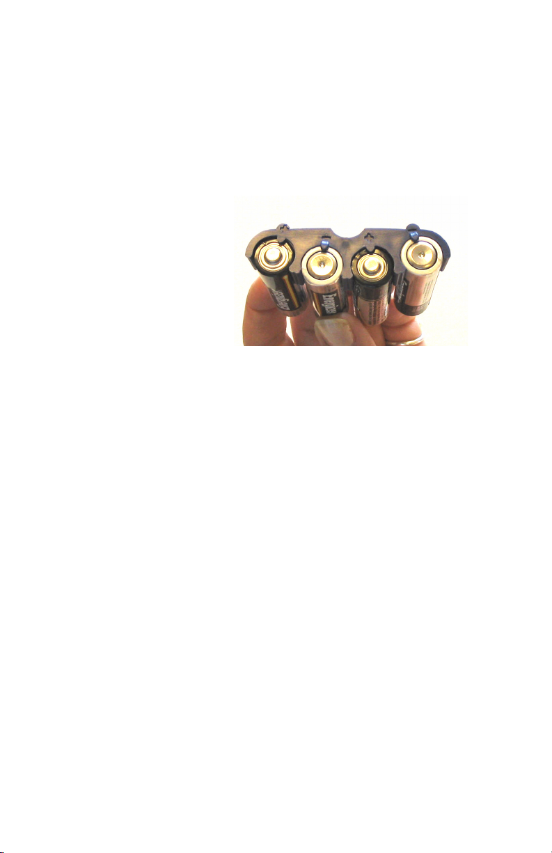
Powering the MobileMapper Beacon...................................................5
Powering the MobileMapper Beacon...................................................9
Belt-mounting.....................................................................................10
Bluetooth Wireless Communications with MobileMapper CE..........11
Establishing a Bluetooth Connection............................................12
Serial Communications ......................................................................13
Serial Port Parameters ........................................................................14
Beacon Lock .......................................................................................15
Knowing What Beacon Station To Use..............................................15
MobileMapper CE Bluetooth Manager ..............................................16
Windows CE Configuration Utility....................................................17
Differential Mode .........................................................................17
Tuning the Beacon Frequency ......................................................18
Monitoring Reception Performance..............................................20
Beacon Interference............................................................................20
Troubleshooting Reception ................................................................21
Coast Guard DGPS Service .....................................................................23
Radiobeacon Range ............................................................................23
Radiobeacon Reception ......................................................................24
Spatial Decorrelation ..........................................................................25
Coast Guard Beacon vs WAAS/EGNOS ...........................................25
Benefits of Coast Guard Beacon...................................................25
Benefits of WAAS/EGNOS..........................................................26
Radiobeacon DGPS ............................................................................27
Radiobeacon Coverage.......................................................................28


1
Preface
Welcome to the Thales MobileMapper™ Beacon User Man-
ual and thank you for buying this high-performance, belt-
mounted DGPS system. This product is an accessory to the
MobileMapper and MobileMapper CE handheld GPS/GIS
data collection systems. The purpose of the MobileMapper
Beacon system is to receive accuracy-enhancing corrections
from Coast Guard beacon networks.
Coast Guard differential GPS beacons have been installed
throughout many locations in the world, and send GPS cor-
rections to users in order to improve GPS accuracy and in-
tegrity, using a medium frequency signal. This service
facilitates the Coast Guard requirements to provide a safe
navigation and position service to its users. Over the last
many years, Coast Guard beacons have been used to great
success by terrestrial users. In fact, a program is currently in
place to provide dual redundant coverage of beacons
throughout the continental United States for a variety of
land-based uses.
GPS corrections received by the MobileMapper Beacon are
transmitted to the GPS data collection system using Blue-
tooth®(1) wireless technology.
(1) The Bluetooth®trademark and logos are owned by Bluetooth SIG, Inc.
and any use of such marks by Thales is under license. Other trademarks and
trade names are those of their respective owners.

2
The MobileMapper Beacon may also be used with 3rd-party
GPS systems that accept RTCM SC-104 corrections via a
Bluetooth or traditional hard-wired serial connection.
The following figure shows the MobileMapper Beacon sys-
tem.
We have written this document to assist you with learning
how to use the MobileMapper Beacon system, how it oper-
ates with GPS equipment, and provide some general infor-
mation on Coast Guard beacon technology.
Key Features
• Fully integrated Coast Guard beacon receiver and
antenna
• All-day battery life using either four alkaline, 1.5-V Lith-
ium or NiMH rechargeable AA-type batteries
• Integrated Bluetooth wireless technology for communi-
cations with the MobileMapper CE
• Convenient belt-mounted carrying system
• User interface includes a power button and status lights
• Conventional hard-wired serial port for communication
with other GPS equipment via a cable with standard DB9
connector.

3
Introduction
The Thales MobileMapper Beacon system is an accessory to
the Thales MobileMapper CE GPS data collection system.
The MobileMapper Beacon is a self-contained, Coast Guard
beacon receiver system. It features an internal beacon re-
ceiver and magnetic field beacon antenna, wireless commu-
nications, and a compartment for 4 AA batteries.
The following figure illustrates the use of the MobileMapper
Beacon.
Receiving Your Shipment
If you find that any of the items are damaged due to ship-
ment, please contact the freight carrier immediately for as-
sistance. If you find that the system is incomplete for some
reason, please contact your point of sale for assistance.
MobileMapper Beacon System
Each MobileMapper Beacon system is composed of:
• MobileMapper Beacon Coast Guard beacon receiver unit
• 4 AA Batteries
• Belt-mounted carrying system
•1 battery clip for easy loading of batteries
• Warranty card
• User Manual
• A PC-interface cable for serial communications.
Note - Though the
MobileMapper Beacon
is primarily intended for
use with our
MobileMapper and
MobileMapper CE GPS/
GIS data collections sys-
tems, it may be used with
any GPS system that
support RTCM-based
real-time differential
corrections. In order to
connect to other devices,
you will need to ensure
the GPS supports either
Bluetooth wireless tech-
nology or an RS-232
serial port.

4
Using the MobileMapper Beacon
User Interface
The MobileMapper Beacon user interface is located on the
top of the unit. This interface consists of a power button and
three lights. A red light next to the power button indicates the
unit is on. A green light comes on once the unit has locked
onto a DGPS transmitter with a signal-to-noise ratio greater
than seven and is sending the corrections to the GPS receiv-
er. A blue light next to the Bluetooth symbol is illuminated
when the unit is sending the corrections to the GPS receiver
via the Bluetooth connection.
The following picture shows the status lights and power but-
ton located on the top surface of the product. Please note the
power button and indicator lights are visible through a cut-
out located on the top of the pouch, supplied with the system.

5
The following table provides detail regarding the status
lights.
Powering the MobileMapper Beacon
The MobileMapper Beacon system includes four AA alka-
line batteries for power. You may alternatively use four
1.5-V Lithium batteries (such as the Energizer® e² Lithium)
or four NiMH (nickel metal hydride) rechargeable batteries,
as long as you do not mix battery types.
NiMH batteries, being rechargeable, offer economy but if
you are going to work in cold weather, you should be aware
that the charge capacity of NiMH technology decreases with
falling temperatures.
Please also keep in mind that if you use NiMH batteries, they
need to be freshly charged before use if they are been stored
for a long period of time.
Although you may load individual batteries into the Mo-
bileMapper Beacon, the system includes two battery clips to
ease battery loading. You may insert four AA batteries into
each of the clips, drop one clip into the battery compartment
and store the spare clip in the mesh pouch on the side of the
belt-mounted carrying system.
LED Color Function
Red
Power indicator - when the MobileMapper Beacon is powered,
this LED will solidly illuminate. Note: This LED does not have a
label, but is connected to the Power Button to indicate what it
is for.
Blue
Bluetooth indicator - this LED will illuminate when there is a
Bluetooth connection between the MobileMapper Beacon and
a Bluetooth compatible device and off when there is no Blue-
tooth connection.
Green
Beacon lock indicator - this indicator will illuminate continu-
ously when the MobileMapper Beacon has achieved a solid
beacon lock with an SNR (signal to noise ratio) of greater than
7.
This product is
intended for use with
regular 1.5-V,
rechargeable and non-
rechargeable, AA bat-
teries. Do NOT use
higher voltage batter-
ies (including 3.6V Li-
SOCl2 AA cells) as
these will cause dam-
age to the unit.

6
The easiest way to insert batteries into a clip is by sliding
them up from under the clip. There are some moulded stops
designed for the proper alignment of the batteries in the clip.
This ensures that the battery terminals make the proper con-
tact when the compartment door is fastened to the unit.
It is important to insert the batteries into the clip with alter-
nating polarity. A fully loaded clip is shown below.
As shown on this photo, the polarity of the batteries is posi-
tive, negative, positive, negative. You can easily slide the
batteries up and into the clip.
The battery clips are also marked with plus and minus signs
to indicate the polarity of the batteries. If you use batteries
without polarity markings, just remember that the flat end is
negative and the end with the raised knob is positive.

7
It is not necessary to remove the MobileMapper Beacon
from the belt-mounted carrying system in order to open the
battery compartment. Just unscrew the knurled silver knob
until you feel the compartment door come loose and pull the
door away from the unit.
You will find that the fastener disengages and 'pops' toward
you. You can then use the fastener to open the door.
At this point, you may load either four individual batteries
into the MobileMapper Beacon, or load the batteries into the
clip and insert the clip assembly into the battery compart-
ment. The battery clip easily inserts into the compartment.

8
To secure the battery compartment door, slide it into place.
Now gently push the door down until the gasket engages.
Pressing the door down, screw the knurled knob into the unit
assuring a good seal.
Warning - Please use only batteries of the same type. Do not
mix alkaline batteries with 1.5-V Lithium or NiMH batteries.
Please do not mix batteries of different charge levels. This can
cause the batteries to fail, causing damage to you or the Mo-
bileMapper Beacon.

9
Powering the MobileMapper Beacon
To turn on the MobileMapper Beacon, press the black, re-
cessed power button on the top of the unit as seen in the pho-
tographs below. When powered, the red LED light turns on.
When the MobileMapper Beacon is turned off, it still draws
a small amount of current from the batteries. If you will not
use the receiver for a number of weeks, you may wish to re-
move the batteries so they do not lose their charge. You may
place the batteries in the belt-mounted carrying system so
you know to place them back in the receiver prior to use.

10
Belt-mounting
The MobileMapper Beacon is designed to mount easily onto
a belt using the included carrying system. You may alterna-
tively carry the Beacon in a backpack or mount it on a range
pole in some fashion. Wherever you carry the MobileMap-
per Beacon, please be sure to separate it from your GPS re-
ceiver or any other electronic device (cell phone, PDA, etc.)
by at least 75 centimeters (30 inches) to prevent radio inter-
ference. You should also keep the top of the Beacon horizon-
tal to optimize signal reception. This is easy to do if you
place the Beacon on your belt on the hip opposite to the hand
you use to carry your MobileMapper or MobileMapper CE
receiver. For example, if you will carry the GPS receiver in
your left hand, place the MobileMapper Beacon on your
right hip. Doing this keeps the Beacon away from the GPS
receiver, it keeps the top horizontal and it allows you to
check reception status by looking at the LEDs on the top of
the unit.
The belt-mounted carrying system has an open bottom so
you can easily access the battery compartment, use an exter-
nal beacon antenna or attach a serial data cable to the unit
without having to remove it from the carrying system.

11
Bluetooth Wireless Communications with
MobileMapper CE
The MobileMapper Beacon's primary method of communi-
cating coast guard beacon corrections to the MobileMapper
CE system is via an internal Bluetooth wireless communica-
tions module. This module is a license-free transceiver that
may be used in majority of countries throughout the world,
and operates at 2.4 GHz.
Bluetooth wireless communications is a convenient method
to communicate between electronic devices, eliminating the
need for you to connect a cable between the MobileMapper
Beacon and the MobileMapper CE.
The MobileMapper Beacon contains a Power Class 1 Blue-
tooth enabled device that is capable of a maximum range of
100 m with another class 1 device. If you are communicating
with another device that is a Power Class 2, your range will
be limited to a maximum of 10 m.
As Bluetooth transmits and receives at 2.4 GHz, it is a line
of sight system. This means that the MobileMapper Beacon
and the receiving device require a line of sight between them
in order to communicate. This is critical if you are using the
two devices toward their maximum operating rate from each
other. For example, you may use the MobileMapper CE
away from a vehicle, with the MobileMapper Beacon sitting
on the roof instead of wearing it. In this case, both devices
must be able to 'see' each other and be within the range limit.
However, when operating the MobileMapper Beacon near
the other device, such as the MobileMapper CE, you do not
need a line of sight between the two products. In this case,
reflected signals can be tracked off the ground with success.
You can also use a serial
data cable to communi-
cate with the
MobileMapper CE. The
original (non-CE)
MobileMapper receiver
is not Bluetooth-
enabled, and so you
must use a cable link.
This is available as an
option.

12
Establishing a Bluetooth Connection
For details regarding the process of connecting to the Mo-
bileMapper Beacon system with the MobileMapper CE,
consult the section below, "MobileMapper CE Bluetooth
Manager."
When the MobileMapper CE has established a Bluetooth
connection to the MobileMapper Beacon system, a blue
LED will illuminate on the top of the MobileMapper Bea-
con. This blue LED is identified with the Bluetooth logo as
shown in the following figure. A successful Bluetooth con-
nection between these devices will be present as long as the
blue LED light on the MobileMapper Beacon is on.
If you are using the MobileMapper Beacon system with an
alternate GPS system that uses Bluetooth communications,
please follow the instructions for that system on how to per-
form a Bluetooth discovery and make a connection to the
MobileMapper Beacon system.
Note - The Bluetooth
port will not be used for
firmware updates; it is
recommended you use
the serial port for any
software updates.

13
Serial Communications
The second method of communicating with the MobileMap-
per Beacon is through a traditional RS-232 serial port. When
using a serial cable, you will not see the Bluetooth light illu-
minate; however, serial data will be downloading into the
GPS system.
A PC-interface cable is supplied with the MobileMapper
Beacon system for serial communications. This cable will be
used for any firmware upgrade, if required, and for intercon-
nection to GPS systems that do not support Bluetooth wire-
less communications.
On the bottom of the MobileMapper Beacon system, you
will notice that beside the battery door, there is a rubber boot
that covers a data socket. Written on this rubber boot is the
word 'Data'. The round 7-pin connector of the PC-interface
cable plugs into this socket. There is a white dot on both the
socket and the 7-pin plug of the cable. To mate these connec-
tors, align the two dots together and simply push the connec-
tor onto the socket. To remove the connector, you will need
to squeeze the two locking clips on either side of the 7-pin
connector of the cable.
To attach the serial cable to the MobileMapper Beacon, line
up the white dots on both connectors.
When not using serial
communications, please
ensure that the rubber
boot is pushed onto the
data socket at all times.
This will protect the con-
nector from water and
dust.

14
To remove the cable, squeeze the tabs on either side of the
cable and gently pull it out.
Serial Port Parameters
If you wish to use the MobileMapper Beacon with non-Tha-
les GPS equipment without Bluetooth wireless technology,
you may need to use conventional serial communications be-
tween the two systems. In this case, you will need to know
the port settings of the MobileMapper Beacon, which fol-
low:
• Baud Rate: 4800
• Data bits: 8
• Stop bits: 1
•Parity:None
In the event that you are
connecting the
MobileMapper Beacon
to a non-Thales-branded
GPS receiver, you may
need to plug a gender
changer and null modem
adapter into the DB9
end of the Beacon's
serial cable.
Using the optional serial
cable (P/N 980816), it is
easy to connect Thales
MobileMapper to
MobileMapper Beacon.

15
Beacon Lock
When a signal from a coast guard beacon station has been ac-
quired, the green lock indicator light will illuminate as
shown below. If you are operating in a weak signal environ-
ment, or with sufficient environmental noise to cause inter-
ference with the signal, this light will either be intermittently
illuminated or may not come on at all. We recommend that
you trouble-shoot a no-lock condition by using the Differen-
tial GPS configuration tool supplied in the GPS Utilities
folder of the MobileMapper CE or the standalone Mo-
bileMapper Beacon configuration utility that can be down-
loaded from ftp.thalesnavigation.com.
Using this tool, you can tune the Beacon to specific frequen-
cies and coast guard beacon stations and monitor the current
frequency or station being used and the resulting reception
performance.
Knowing What Beacon Station To Use
Thales publishes a beacon listing that provides beacon sta-
tion details around the world. Often, beacon site details
change or new stations are added, so please check with your
local Thales Navigation office for updates.

16
MobileMapper CE Bluetooth Manager
In order to use corrections from the MobileMapper Beacon,
the MobileMapper CE's Bluetooth Manager must first be
used to discover the Beacon product, and then establish a
connection.
To access the Bluetooth Manager:
• Tap the Windows butterfly icon in the lower left of the
MobileMapper CE screen with the stylus.
• Then access Settings>Control Panel>BTManager. The Blue-
tooth icon will appear in the system tray.
To turn the Bluetooth function on or off, you will need to tap
on the Bluetooth icon. A window will pop up. From here,
you will be able to turn this communications feature on or
off. Ensure that your MobileMapper Beacon system is near-
by and powered. When turned on, the Bluetooth Manager
will proceed to initiate a discovery of nearby Bluetooth-ca-
pable systems. The results of this process are displayed be-
low the on and off buttons.
When the discovery is complete, you should see the Mo-
bileMapper Beacon system displayed as 'MMBEACON
xxxxx', where 'xxxxx' is the last five digits of the multimedia
access code (MAC) address, indicated on the serial label of
the MobileMapper Beacon system.
If you press the 'plus (+)' box beside the 'MMBEACON
xxxxx' device, you will notice that the supported service is
'BLUETOOTHSERIAL'. Using the stylus, tap and hold on
the service name. A menu will pop up and choose 'connect'.
In a few moments, you should see the Bluetooth indicator
light on the MobileMapper Beacon illuminate. The Mo-
bileMapper CE will also indicate a Bluetooth connection.
To make sure that your
MobileMapper CE
handheld will
automatically connect to
the same MobileMapper
Beacon device each time
you turn on the system,
in the context-sensitive
menu tied to the chosen
Bluetooth
Serial Port, check Auto
Connect.
Table of contents
Other Thales GPS manuals