Thales DVOR 432 User manual

Reference No. 83130 55024
Doppler
Operation and Maintenance
DVOR 432
Technical Manual
As for details, the electrical and echanical infor ation given in the
docu entation supplied with each equip ent prevails
Part 2
All rights reserved
E2004
Thales ATM G bH
Stuttgart
Printed in Ger any
VHF Omnidirectional Radio Range

NAVAIDS
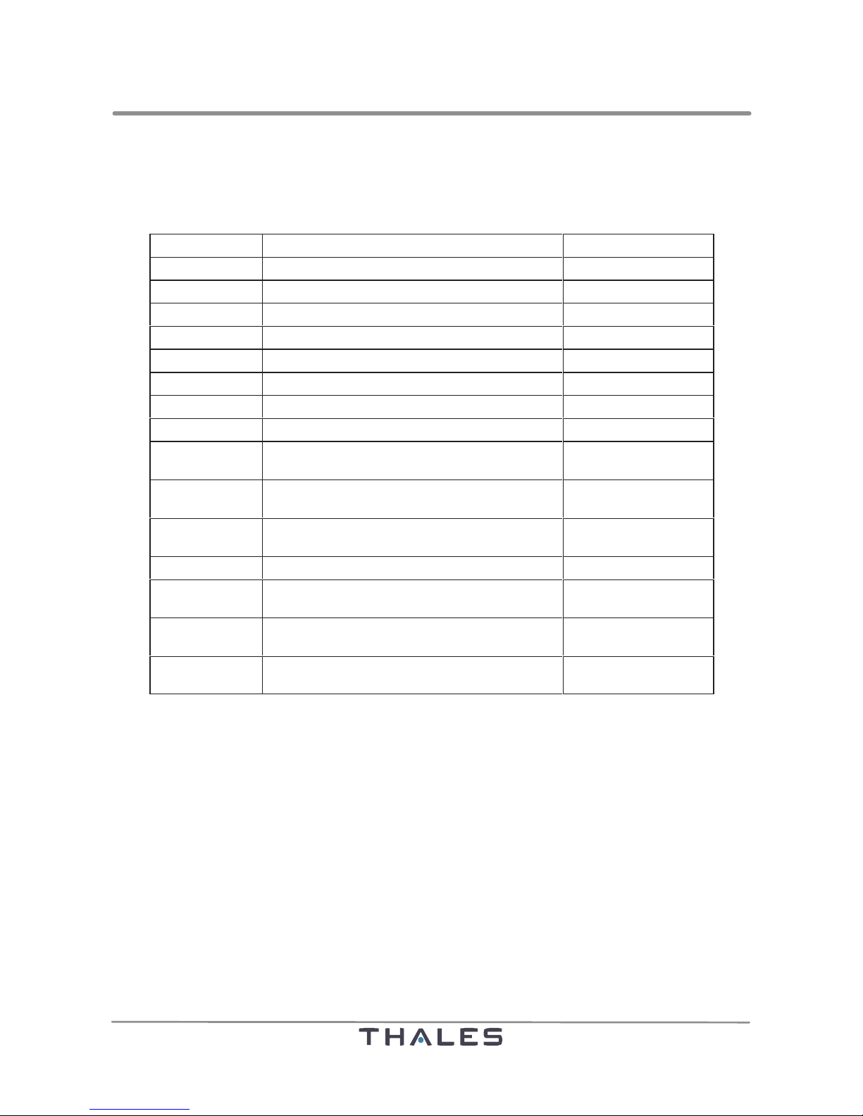
Conventional Navaids Documentation Structure
Ed. 01.04
DVOR 432
The equip ent docu entation co prises:
Part Technical Man als Code No.
1Equip ent Description (incl. Annex NF) 83130 55023
2 Operation and Maintenance (incl. Annex NF) 83130 55024
Vol me Drawing Set Code No.
Standard
A Delivery List, Parts List,
Sche atic diagra s and Layout Drawings
83051 48620
B Delivery List, Parts List,
Sche atic diagra s and Layout Drawings
83051 48620
C Delivery List, Parts List,
Sche atic diagra s and Layout Drawings
83051 48620
Nextfield (option)
A Delivery List, Parts List,
Sche atic diagra s and Layout Drawings
83051 48640
B Delivery List, Parts List,
Sche atic diagra s and Layout Drawings
83051 48640
C Delivery List, Parts List,
Sche atic diagra s and Layout Drawings
83051 48640

DVOR 432
Operation and Maintenance Preliminary Remarks
AEd. 01.04
PRELIMINARY REMARKS
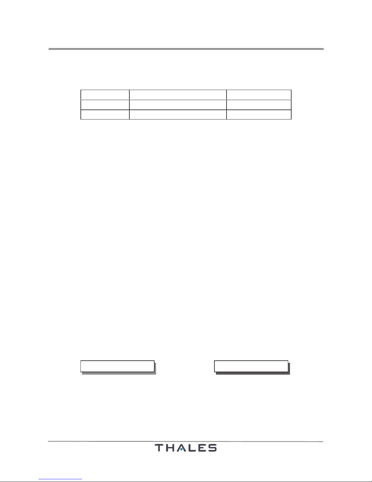
The equip ent anuals for DVOR 432 (50 W and 100 W, single or dual) co prise:
PART CONTENTS CODE NO.
1Equip ent Description 83130 55023
2 Operation and Maintenance 83130 55024
This Technical Manual Part 2 includes the Operation and Maintenance with the chapters below:
1General Infor ation
2Installation
3Operation
4Align ent Procedure
5Maintenance
6Fault Location and Repairs
Annex DVOR Nextfield (optional)
The 50 W and 100 W installations differ only slightly with respect to equip ent, functions and operaĆ
tion, separate descriptions are not therefore provided for these two versions, but instead any special
features of either are pointed out. The content of part 1 "Equip ent Description" will as well-known
presupposed. Installation and allign ent procedure of the nextfield onitoring option is described
in the Annex to this anual.
Since it is not possible to include odifications, such as those which ay be ade to circuitry details
or di ensioning in the interests of technical progress, in the Technical Manual, we should point out
that questions of detail should always be answered using the technical docu entation supplied with
the syste . It is possible that reference nu bers of drawings or subasse blies used in this descripĆ
tion are no longer contained in the set of drawings supplied (Volu e A to C), but rather than (to conĆ
for with the syste ) they have been replaced by new drawings with another nu ber. Please carry
out a once-only check on the basis of delivery list supplied and exchange where appropriate.
Description and use of the PC User Program will be found in the Technical Manual ADRACS, Code
No. 83140 55324.
MARK SYMBOLS
To get the best out of the navigation syste s Navaids 400 you should study the contents of this anuĆ
al carefully. In particular you should fa iliarize yourself with the arks given in this anual which are
highlighted for easy recognition:
Cautions call attention to ethods
and procedures which ust be
followed to avoid da age to
equip ent.
Warnings call attention to ethods,
procedures or li its which ust be
followed precisely to avoid injury to
persons.
NOTE or REMARK : For ore infor ation about operations.
CAUTION WARNING

DVOR 432
Preliminary Remarks Operation and Maintenance
BEd. 01.04
Table of effective pa es
Basic edition: 01.02 / Revised edition: 01.04
Pa es Ed.-No. Remarks
Title 01.04
A to B 01.04
I to X 01.04
AV-1 to 16 01.04
1-1 to 10 01.04
-1 to 46 01.04
3-1 to 16 01.04
4-1 to 3 01.04
5-1 to 14 01.04
6-1 to 36 01.04
Annex 01.04 DVOR Nextfield (optional)
Trademarks: Microsoft and MS-DOS are registered trademarks, WINDOWS is a trademark of the Microsoft Corporation. IBM is a registered trademark of the International
Business Corporation. Pentiumis a registered trademark of the Intel Corporation. All other mentioned product names may be trademarks of the respective
manufacturers and must be observed.
Note Despite of careful editing work technical inaccuracies and printing faults cannot be excluded in this publication. Change of text remains reserved without notification.

DVOR 432
Operation and Maintenance Table of Contents
IEd. 01.04
TABLE OF CONTENTS
Section Title Page
CHAPTER 1 GENERAL INFORMATION 1-1...........................................
1.1 STORING AND UNPACKING THE EQUIPMENT 1-1........................
1.1.1 General 1-1........................................................
1.1.2 Unpacking 1-1......................................................
1.2 STORING AND UNPACKING THE DVOR ANTENNAS 1-3...................
1.3 GENERAL INSTALLATION INFORMATION 1-4.............................
1.3.1 Safety Precautions 1-4..............................................
1.3.1.1 General Rules 1-4......................................................
1.3.1.2 Precautionary Measures against Da age caused by Ani als 1-4............
1.3.1.3 Equip ent Notes 1-4...................................................
1.3.2 Personnel Require ent 1-5..........................................
1.3.3 Tools and Special Materials 1-5.......................................
1.4 LIST OF RECOMMENDED INSTRUMENTS AND ACCESSORIES 1-7.........
CHAPTER 2 INSTALLATION 2-1.....................................................
2.1 SELECTING THE INSTALLATION SITE 2-1................................
2.2 FOUNDATIONS FOR DVOR COUNTERPOISE AND SHELTER 2-2...........
2.3 DVOR CONTAINER SHELTER 2-5........................................
2.3.1 General 2-5........................................................
2.3.2 Transportation and Installation of the Container Shelter 2-5...............
2.4 INSTALLATION OF THE DVOR ANTENNAS 2-7............................
2.4.1 General 2-7........................................................
2.4.1.1 Prerequisites 2-7.......................................................
2.4.2 Antenna ounting 2-8...............................................
2.4.2.1 Lifting the Antennas onto the Counterpoise 2-8............................
2.4.2.2 Installation of the Carrier Antenna 2-8....................................
2.4.2.3 Installation of the Sideband Antennas 2-9.................................
2.4.3 RF Cabling of Antennas 2-11..........................................
2.4.3.1 General 2-11...........................................................
2.4.3.2 Carrier Antenna 2-11....................................................
2.4.3.3 Sideband Antennas 2-11.................................................
2.4.4 Preli inary Settings and echanical Align ent of the Sideband 2-13......
Antennas

DVOR 432
Table of Contents Operation and Maintenance
II Ed. 01.04
Section Title Page
2.4.5 Installation of the Monitor Dipole 2-15..................................
2.4.6 Conversion of S3000 Antennas to S4000/NAV400 Antennas 2-16..........
2.5 INSTALLATION AT THE RACK IN THE SHELTER 2-17.......................
2.5.1 General 2-17........................................................
2.5.2 Power Supply 2-17...................................................
2.5.2.1 Power Connections 2-17.................................................
2.5.2.2 Connection of Battery Set 2-19...........................................
2.5.3 Connections at Trans itter and ASU Rack 2-22..........................
2.5.3.1 RF/AF Connections 2-22.................................................
2.5.3.2 Pin-Assign ent ASU Interface Connector (intern, SubD, 37pin, fe ale) 2-23..
2.5.3.3 Connection ASU to Antennas 2-23........................................
2.5.4 External Interface Connection 2-25.....................................
2.5.4.1 DME IDENT 2-25.......................................................
2.5.4.2 DIAGNOSIS 2-25.......................................................
2.5.4.3 LGM1 2-25.............................................................
2.5.4.4 LGM2/DME 2-26........................................................
2.5.4.5 LGM3/NDB 2-26........................................................
2.5.4.6 ANALOG 2-27..........................................................
2.5.4.7 Local PC 2-27..........................................................
2.5.4.8 VAM 2-27..............................................................
2.5.4.9 OIO LCP IN 2-27........................................................
2.5.4.10 OIO LCP OUT 2-28.....................................................
2.5.5 External Interfaces, Cable Connections 2-29.............................
2.5.5.1 Connection of Re ote Control RMMC 2-29................................
2.5.5.2 Connection of a local PC or Laptop 2-29...................................
2.5.5.3 Connection of Voice Signal for VAM 2-29..................................
2.5.5.4 Connection of auxiliary Inputs/Outputs (LCP) 2-29..........................
2.5.5.5 Connection of auxiliary Analog and Te p inputs (CSL) 2-29..................
2.6 GROUNDING 2-33......................................................
2.6.1 General 2-33........................................................
2.6.2 Strip or esh Ground Conductors 2-33.................................
2.6.3 Ground Rods 2-34...................................................
2.6.4 Ground Plates 2-34..................................................
2.6.5 Esti ating the Ground Resistance 2-34.................................

DVOR 432
Operation and Maintenance Table of Contents
IIIEd. 01.04
Section Title Page
2.6.6 Measuring the Ground Resistance 2-35.................................
2.7 COLLOCATION WITH DME 2-37..........................................
2.7.1 Overview 2-37.......................................................
2.7.2 Connection of FSD 40/45 to DVOR 432 2-37............................
2.7.2.1 CSB-Version, I/O-panel at the rear of cabinet 2-37........................
2.7.2.2 CSB-Version, I/O-panel on top of the cabinet 2-37........................
2.7.2.3 IOM-Version 2-38......................................................
2.7.2.4 Configuration of DVOR 432 and DME FSD 40/45 2-38.......................
2.7.3 Connection of DME 415/435 to DVOR 432 2-44..........................
2.7.3.1 Ident and RS232 connection 2-44.........................................
2.7.3.2 Configuration of DVOR 432 and DME 415/435 2-44.........................
2.8 INSTALLATION OF THE DME ANTENNA 2-46..............................
CHAPTER 3 OPERATION 3-1.......................................................
3.1 GENERAL 3-1.........................................................
3.2 LOCAL CONTROL INTERFACE 3-1......................................
3.2.1 Indication La ps for Main Status 3-2..................................
3.2.2 Liquid Crystal Display Screen for Indication and Control of the Syste 3-2.
3.2.2.1 General Structure 3-2..................................................
3.2.2.2 Welco e Window 3-4..................................................
3.2.2.3 Syste Status Windows 3-4.............................................
3.2.2.4 Syste Control Windows 3-8............................................
3.2.2.5 Syste DATA Window 3-10..............................................
3.2.2.6 MENU LIST Window 3-11...............................................
3.2.3 Key-lock Switch on LCP front Panel 3-12...............................
3.3 CONTROLS AND INDICATIONS ON THE SUBASSEMBLIES 3-13.............
3.4 NORMAL OPERATION 3-16..............................................
3.4.1 Switching On 3-16...................................................
3.4.2 Change over fro Re ote to Local (on LCI) 3-16........................
3.4.3 Change Over to Maintenance Operation 3-16............................
3.4.4 Change over to Monitor Bypass 3-16...................................
3.4.5 Acoustic Alar 3-16..................................................
3.4.6 Monitoring ATIS or Voice 3-16.........................................
3.4.7 Functional Check of Indications 3-16...................................
3.4.8 Switching Off 3-16...................................................

DVOR 432
Table of Contents Operation and Maintenance
IV Ed. 01.04
Section Title Page
CHAPTER 4 ALIGNMENT PROCEDURE 4-1..........................................
4.1 GENERAL PREREQUISITES 4-3.........................................
4.2 FIRST SWITCHING ON 4-5.............................................
4.3 MATCHING OF ANTENNAS 4-7..........................................
4.4 CHECK OF DECOUPLING BETWEEN SIDEBAND ANTENNAS 4-9...........
4.5 CALIBRATION OF MONITORS 4-11.......................................
4.6 SETTING OF TRANSMITTERS AND MONITORS 4-13.......................
4.7 RECORDING OF SIMULATOR-ERROR-CURVE 4-18......................
4.8 SETTING OF MONITOR ALARM LIMITS 4-19...............................
4.9 BATTERY MONITORING 4-21............................................
4.10 NORMAL OPERATION 4-22..............................................
4.11 FLIGHT CHECK 4-23....................................................
4.12 RELATIONSHIP BETWEEN THE MONITOR DISPLAY OF THE RF LEVEL 4-31..
AND THE POWER
CHAPTER 5 MAINTENANCE 5-1....................................................
5.1 GENERAL 5-1.........................................................
5.2 PERIODIC MAINTENANCE 5-1..........................................
5.2.1 Eli ination of Static Charges 5-2........................................
5.2.2 Da age check 5-2..................................................
5.2.3 Cleaning 5-2.......................................................
5.2.4 Docu entation of Syste Data 5-3...................................
5.3 NORMAL MAINTENANCE 5-4...........................................
5.3.1 Replacing the Lithiu Batteries (MSP-C, MSP-VD, LCP) 5-4...............
5.3.2 Maintaining E ergency Battery 5-5...................................
5.3.2.1 Battery Voltage 5-5.....................................................
5.3.3 Matching the Charging Voltage of BCPS Modules 5-5...................
5.3.3.1 Reasons for Voltage Matching 5-5.......................................
5.3.3.2 Matching the Voltage 5-6...............................................
5.4 STARTUP, CARE AND MAINTENANCE OF THE LEAD BATTERY 5-7..........
5.4.1 Startup Specifications for the Lead Battery in Navigation Installations 5-7..
5.4.1.1 General 5-7...........................................................
5.4.1.2 Preli inary Operations 5-8..............................................
5.4.1.2.1 Accu ulator Acid and Specially Purified Water 5-8.........................
5.4.1.2.2 Mixing Sulphuric Acid 5-8...............................................

DVOR 432
Operation and Maintenance Table of Contents
VEd. 01.04
Section Title Page
5.4.1.2.3 Relationship between the Acid Density and the Te perature 5-9.............
5.4.1.2.4 Basic Rules for Handling Batteries 5-10....................................
5.4.1.2.5 Filling the Batteries with Acid 5-11.........................................
5.4.1.3 Startup 5-11............................................................
5.4.1.3.1 General 5-11...........................................................
5.4.1.3.2 Dry Pre-charged Batteries 5-11..........................................
5.4.1.3.3 Non Pre-charged Batteries 5-11..........................................
5.4.1.3.4 Initial Charging 5-12.....................................................
5.4.2 Care and Maintenance of the Lead Battery 5-13..........................
5.4.2.1 Maintenance Accessories and Scope of Checks 5-13........................
5.4.2.1.1 Keeping the Lead Battery Clean 5-14......................................
5.4.2.1.2 Measuring the Acid Density (not for aintenance-free batteries) 5-14.........
5.4.2.1.3 Topping Up the Cells (not for aintenance-free batteries) 5-14...............
5.4.2.1.4 Measuring the Cell Voltage 5-14..........................................
CHAPTER 6 FAULT LOCATION AND REPAIR 6-1......................................
6.1 FAULT LOCATION 6-1..................................................
6.1.1 General 6-1........................................................
6.1.2 Fault Evaluation with PC and ADRACS 6-1.............................
6.1.3 Fault Location Support DVOR (50 W and 100 W) 6-1....................
6.1.3.1 Power Supply and Module Indicators 6-1.................................
6.1.3.2 Localization of the defective Equip ent Part (1) 6-2........................
6.1.3.3 Status Check of the Microprocessor of the MSG-C (2) 6-2.................
6.1.3.4 RF-Level too low or issing (3) 6-3.....................................
6.1.3.5 Modulation Depth of Carrier too low (4) 6-4...............................
6.1.3.6 Modulation by Sidebands too low or wrong (5) 6-5.........................
6.1.3.7 Wrong Carrier Frequency (6) 6-8.........................................
6.1.3.8 Azi uth Indication (7) 6-8...............................................
6.1.3.9 Fault in the Monitor (8) 6-9..............................................
6.1.3.10 Fault of the Local Control Panel (LCP) (9) 6-11..............................
6.2 REPAIRS 6-13..........................................................
6.2.1 General 6-13........................................................
6.2.1.1 Safety precautions 6-13..................................................
6.2.1.1.1 General regulations 6-13.................................................
6.2.1.1.2 Work on the equip ent 6-13.............................................

DVOR 432
Table of Contents Operation and Maintenance
VI Ed. 01.04
Section Title Page
6.2.1.1.3 Handling Electrostatically Sensitive Subasse blies 6-13.....................
6.2.1.1.4 Co ponents containing berylliu oxide cera ics 6-14......................
6.2.1.1.5 Handling lead batteries 6-14..............................................
6.2.2 Correcting a Processor Standstill 6-15..................................
6.2.2.1 Failure in the Monitor Processor 6-15......................................
6.2.2.2 Failure in the Trans itter Processor 6-15...................................
6.2.3 Replacing Subasse blies 6-17........................................
6.2.3.1 Disconnecting the Voltage before replacing Subasse blies 6-17..............
6.2.3.2 Subasse blies in the Trans itter Rack and Power Supply 6-17...............
6.2.3.2.1 Replacing EPROM 6-19..................................................
6.2.3.2.2 Creating new Checksu for MSP EPROM in ADRACS 6-19..................
6.2.3.2.3 Replace and Reconfigure Subasse bly LCP 6-20...........................
6.2.3.3 DVOR antenna 6-20.....................................................
6.2.4 List of DIP-FIX-Switches and Ju pers 6-21............................
6.2.4.1 General 6-21...........................................................

DVOR 432
Operation and Maintenance Table of Contents
VIIEd. 01.04
LIST OF FIGURES
Fig.-No. Title Page
Fig. 1-1 DVOR in 10 ft container shelter for all types of transport 1-1.................
Fig. 1-2 DVOR with packing for rail or road transport 1-1...........................
Fig. 1-3 Packaging for rail and road transport 1-2..................................
Fig. 1-4 Packaging for and transport of the DVOR antenna do es 1-3...............
Fig. 2-1 DVOR siting criteria (general data) 2-1....................................
Fig. 2-2 Foundations for DVOR Shelter (for infor ation only) 2-2....................
Fig. 2-3 Foundations for DVOR counterpoise and shelter (for infor ation only) 2-3....
Fig. 2-4 10 ft DVOR container shelter 2-5.........................................
Fig. 2-5 Correct lifting with a lifting harness 2-5....................................
Fig. 2-6 Standard shelter, ground plan and electrical installation DVOR (exa ple) 2-6..
Fig. 2-7 Antenna ring 2-7.......................................................
Fig. 2-8 Pipes for guiding the antenna cables 2-8..................................
Fig. 2-9 Lifting equip ent for DVOR antenna installation 2-8........................
Fig. 2-10 Installation of vertical pipes and installation point of antenna 1 2-9...........
Fig. 2-11 Installation direction of vertical pipe and antenna do e 2-9.................
Fig. 2-12 Spacing of vertical pipes of sideband antenna 2-10.........................
Fig. 2-13 Antenna ring, single antenna and vertical pipe 2-10.........................
Fig. 2-14 Connection diagra of individual radiators of the sideband antennas 2-11.....
Fig. 2-15 Sideband antenna with atcher/decoupling odule pulled out 2-11..........
(e.g.: antenna 2)
Fig. 2-16 Cabling of sideband antenna 2-12........................................
Fig. 2-17 Cabling to the shelter 2-12...............................................
Fig. 2-18 Calibration capacitors on the antenna ele ents 2-13........................
Fig. 2-19 Plate separation distance of capacitors CA as a function of 2-14..............
the operating frequency
Fig. 2-20 Aligning the sideband antenna with the aid of bearing arkers 2-14...........
Fig. 2-21 Diagra atic site layout of DVOR onitor dipole 2-15......................
Fig. 2-22 Mast with onitor dipole (exa ple) 2-15...................................
Fig. 2-23 Connections at the BCPS connection plate, C-bar and botto plate 2-20.....
(100 W version)
Fig. 2-24 Cabling, BCPS connection plate, C-bar and botto plate (100 W version) 2-21
Fig. 2-25 DVOR trans itter and ASU rack, top view, connectors 2-22..................
Fig. 2-26 DVOR ASU rack, front side, connections 2-23..............................
Fig. 2-27 External wiring of auxiliary OIO connectors of LCP 2-29......................

DVOR 432
Table of Contents Operation and Maintenance
VIII Ed. 01.04
Fig.-No. Title Page
Fig. 2-28 Interface connections trans itter cabinet, rear side 2-30.....................
Fig. 2-29 Syste cabling DVOR 2-31..............................................
Fig. 2-30 Different types of ground conductor configuration 2-33......................
Fig. 2-31 Deter ining of the ground resistance 2-35.................................
Fig. 2-32 Interface Assign ent of LGM2 and DME-Ident in DVOR 432 2-39............
Fig. 2-33 AF-distribution box, assign ent of ter inals (exa ple) 2-39................
Fig. 2-34 CSB-Version, I/O panel at cabinet rear side, connection DVOR to DME 2-40...
Fig. 2-35 CSB-Version, I/O panel at cabinet rear side, ident connection 2-40..........
DVOR to DME
Fig. 2-36 CSB-Version, I/O panel at cabinet rear side, RS 232 connection 2-40........
DVOR/DME
Fig. 2-37 CSB-Version, I/O panel on cabinet top, connection DVOR to DME 2-41.......
Fig. 2-38 CSB-Version, I/O panel on cabinet top, ident connection DVOR/DME 2-41....
Fig. 2-39 CSB-Version, I/O panel on cabinet top, RS 232 connection DVOR/DME 2-41..
Fig. 2-40 IOM-Version, connector panel at cabinet rear side, connection 2-42.........
DVOR to DME
Fig. 2-41 IOM-Version, connector panel at cabinet rear side, ident connection 2-42....
DVOR/DME
Fig. 2-42 IOM-Version, connector panel at cabinet rear side, RS 232 connection 2-42..
DVOR/DME
Fig. 2-43 Cable connections to DVOR and DME FSD 40/45 2-43......................
(DME with individual internal or external ode for RC connection)
Fig. 2-44 Cable connections to DVOR and DME 415/435 2-43........................
(DME with individual internal or external ode for RC connection)
Fig. 2-45 Collocation CVOR/DVOR with DME 415/435 2-45...........................
Fig. 2-46 Ident connection CVOR/DVOR to DME 415/435 2-45........................
Fig. 2-47 RS232 connection CVOR/DVOR to DME 415/435 2-45.......................
Fig. 2-48 Arrange ent and installation of the DME antenna (exa ple AAN 86), 2-46.....
principle view
Fig. 3-1 Local Control Interface (LCI), exa ple 3-1................................
Fig. 3-2 Liquid crystal display screen of the Local Control Interface (LCI), exa ple 3-2.
Fig. 3-3 Welco e window, exa ple 3-4..........................................
Fig. 3-4 Syste Status window with status 'NORMAL', exa ple 3-5.................
Fig. 3-5 Syste Status window with status 'ALARM', both trans itters 3-5...........
are switched off (shut down), exa ple
Fig. 3-6 Syste Status window with status 'Warning', exa ples 1 3-6................
Fig. 3-7 Syste Status window with status 'WARNING', exa ples 2 3-7..............

DVOR 432
Operation and Maintenance Table of Contents
IXEd. 01.04
Fig.-No. Title Page
Fig. 3-8 Syste Status window with status 'WARNING', exa ple 3 3-8...............
Fig. 3-9 Syste Control window TRANSMITTER CONTROLS, exa ple 3-9...........
Fig. 3-10 Syste Control window MONITOR CONTROLS, exa ple 3-9...............
Fig. 3-11 DATA window to indicate onitoring data 3-10.............................
Fig. 3-12 MENU LIST window, exa ple 3-11........................................
Fig. 3-13 Data Indication window AERIAL TRANSMITTER DATA, exa ple 3-12..........
Fig. 3-14 Key-lock switch and indication of operational ode on LCD screen, 3-12.....
exa ple
Fig. 3-15 Push buttons and indications on the subasse blies inside the rack (1) 3-14....
Fig. 3-16 Push buttons and indications on the subasse blies inside the rack (2) 3-15....
Fig. 4-1 Setting characteristics for DVOR-antenna 4-27.............................
Fig. 4-2 Position of capacitors CA, CTr (antenna do e), C5 4-27....................
( atcher/decoupling odule)
Fig. 4-3 Test setup for atching easure ents for DVOR-antenna 4-28..............
Fig. 4-4 Si ulator test setup for DVOR 4-28.......................................
Fig. 4-5 Trans itter rack, rear side, potentio eters on CCP-D 4-29..................
Fig. 4-6 Test log for si ulator fault plot 4-30.......................................
Fig. 5-1 Accu ulator acid chart 5-8.............................................
Fig. 5-2 Chart showing the relationship between the acid density and 5-9............
the te perature
Fig. 6-1 Push buttons and indications on the subasse blies MSP and 6-16..........
MSG-C in the rack
Fig. 6-2 Preparation and adjust ents during a subasse bly replace ent 6-18........
Fig. 6-3 LCP front panel and LCP control enu 6-20...............................

DVOR 432
Table of Contents Operation and Maintenance
XEd. 01.04

NAVAIDS 400
List of Abbreviations
Conventional Navaids
AV-1Ed. 01.04
ABKÜRZUNGSVERZEICHNIS
LIST OF ABBREVIATIONS
LISTE D'ABRÉVIATIONS
LISTA DE ABREVIATURAS
A Antenne
Antenna
Antena
AC Alternating Current
Courant alternatif
Corriente alterna
ACA Analogical Carrier A plifier (BITE signal)
A plificateur pour porteurs analogiques (signal BITE)
A plificdor portador analogico (señal BITE)
ACC Alternating Current Converter
ADC Analog-Digital Converter
Convertisseur analogique/nu érique
Convertidor analógico/digital
ADCS Analog-to-digital Converter Subsyste
Sous-systè e convertisseur analogique/nu érique
Subsiste a convertidor analógico/digital
ADR Analog Display Routine
Routine affichage analogique
Rutina de indicator analógico
ADRACS Auto atic Data Recording And Control Syste
ADSB Alternating Double Sideband
Bande latérale double alternante
Banda lateral doble alternante
ADU Antenna Distribution Unit
Antennen-Verteileinheit
Ense ble de distribution d'antenne
Unidad de distribución de antena
AF Audio Frequency
Basse fréquence
Audiofrequencia
AFC Auto atic Frequency Control
Co ande auto atique par fréquence
Control auto ático de frecuencia
AGC Auto atic Gain Control
Co ande auto atique de gain
Control auto ático de ganancia
AM A plitude Modulation
Modulation d'a plitude
Modulación de a plitud

NAVAIDS 400
List of Abbreviations Conventional Navaids
AV-2 Ed. 01.04
AMP AMPlifier
A plificateur
A plificador
ANSI A erican National Standards Institute
ASB Alternating SideBand
Bandes latérales alternantes
Banda lateral alternante
ASC Antenna Switch Control
Co utateur d'antennes de co ande
Control de con utador de antena
ASCII A erican Standard Code for Infor ation Interchange
Code standard a éricain pour l'échange d'infor ations
Código stándard a ericano para el interca bio de infor aciones
ASM Antenna Switch Module
Module de co utateur d'antennes
Módulo de con utador de antena
ASU Antenna Switching Unit
Ense ble de co utation d'antennes
Unidad de con utación de antena
ATC Air Traffic Control
Contrôle du trafic aérien
Control del tráfico aéreo
ATIS Air Traffic Infor ation Syste
Systè e d'infor ations du trafic aérien
Siste a de infor aciones del tráfico aéreo
ATM Air Traffic Manage ent
AWD Auto atische Wähleinrichtung für Datenverbindungen
Auto atic dialling equip ent for data connections
Dispositif auto atique de sélection pour liaisons d'ache ine ent de données
Dispositivo auto ático de selección para co unicaciones de datos
BAZ Back-Azi uth
BCD Binär Codiert Dezi al
Binary Coded deci al
BCPS Battery Charging Power Supply
Chargeur de batterie et bloc d'ali entation
Chargador de bateria y equipo de ali entación
BD Baud
Baud
Baudio
BF Basse Fréquency
Audio Frequency
Baja frecuencia (audiofrecuencia)
BIT(E) Built-in Test (Equip ent)
Dispositif de test intégré
Dispositivo de test integrado

NAVAIDS 400
List of Abbreviations
Conventional Navaids
AV-3Ed. 01.04
BKZ BefehlsKennZahl
Co and code nu ber
Nu éro indicatif de co ande
Nú ero indicador de orden
BNC Bayonet Navy Connector
Koaxialverbinder it Bayonetkupplung
BP Backplane
Rückwandverdrahtung
bro. broches
polig
pin
BSE Betriebs- und Schutzerde
Syste and protective ground
Prise de terre de systè e et terre de protection
Puesta a tierra del siste a y de protección
BSG-D Blending Signal Generator
Générateur de signaux de transition
Generador de señal de transición
BST Baustahl
Structure steel
Acier de construction
Acero de construcción
BUSGNT Bus Grant
Autorisation de bus
Autorización de bus
BUSRQ Bus Request
De ande de bus
Solicitud de bus
CA Carrier A plifier
CAB Cabinet
Ar oire
Ar ario
CAT Category
Kategorie
Category
Categoría
CCA Circuit Card Asse bly
Baugruppe
Asse blage de la carte de circuit
CCITT Co itée Consultatif International Téléphonique et Télégraphique
International Telegraph and Telephone Consultative Co ittee
CCP Control Coupler
Coupleur de co ande
Acoplador de control

NAVAIDS 400
List of Abbreviations Conventional Navaids
AV-4 Ed. 01.04
CDI Course Deviation Indicator
Indicateur de déviation (cap)
Indicador de desviaciòn de ru bo
CD-ROM Co pact Disc - Read Only Me ory
Disque co pact -Mé oire à lecture
Disco co pacto - Me oria per anente
CE Confor ité Européen oder/or/ou Co unautés Européennes
CEE International Co ision on Rules for the Approval of Electrical Equip ent
CLR; CL Clearance signal
Signal de Clearance
Señal de Clearance
CMOS Co ple entary Metaloxide Se iconductor
Se i-conducteur oxyde étallique co plé entaire
Se iconductor co ple entario de óxido etálico
CONC Phone Concentrator
Telefon-U schalteinrichtung
Installation de co utation téléphonique
Centralilla teléfonica
CPU Central Processing Unit
Zentrale Prozessoreinheit
CR Carriage Return
Retour du chariot
Retorno de carro
CRC Cyclic Redundancy Check
CRT Cathode Ray Tube
Tube cathodique
Tubo catódico
CRS; CS Course signal
Kurssignal
Signal de directif
Señal de ru bo
CSB (1) Carrier signal with SideBands (HF)
Signal de porteuse avec bandes latérales
Señal de portadora con bandas laterales
CSB (2) Control&Status Board (part of the LCSU)
CSL Control and Selector Logic
Logique de co ande et de sélection
Lógica de control y de selección
CTOL Conventional Take-off and Landing
Décollage et atterrissage classiques
Despegue y aterrizaje convencionales
CTS Clear to Send
Prêt à é ettre
Listo para trans itir
Table of contents
Other Thales GPS manuals

Thales
Thales VesseLINK Certus 350 User manual

Thales
Thales MobileMapper CE User manual
Thales
Thales MobileMapper Beacon User manual

Thales
Thales NSS 100S-1 Setup guide

Thales
Thales MobileMapper CE User manual

Thales
Thales Mobile Mapper User manual

Thales
Thales Z-Max User guide

Thales
Thales CGRS User manual


