Thames & Kosmos Electronics User manual

EXPERIMENT MANUAL
WARNING — Science Education Set. This set contains chemicals
and/or parts that may be harmful if misused. Read cautions on individual
containers and in manual carefully. Not to be used by children except
under adult supervision.

What’s in your experiment kit:
✔No. Description Qty. Item No.
1 Electronics board 1 774090
2 Contact clips (17 pieces) 1 000642
3 Electronic components 1 774100
– Resistor, 470 Ohm (2)
– Resistor, 3.3 Kiloohm (1)
– Resistor, 22 Kiloohm (1)
– Resistor, 100 Kiloohm (1)
– Resistor, 220 Kiloohm (1)
– Electrolytic capacitor, 10 Microfarad (1)
– Electrolytic capacitor, 100 Microfarad (1)
– Transistor module, npn (2)
– Light-emitting diode (LED), green (1)
– Light-emitting diode (LED), red (1)
4 Pushbutton 1 000367
5 Wire bridges, short (10 pieces) 1 000282
6 Wire bridges, long (10 pieces) 1 000292
7 Wire connectors 2 000343
8 Battery clip (for 9-volt battery) 1 712310
Please check all the parts against the list to make sure that nothing is missing.
If you are missing any parts, please contact Thames & Kosmos customer
service.
Checklist: Find – Inspect – Check off
Additional
things you will
need:
→ 9-volt battery
(Type 6LR61)
→ Drinking glass
→ Blotting paper
→ Tape
→ Glue
→ Scissors
→ Paper
→ Cardboard
→ Pencil
→ Various objects (e.g.,
bowl, eraser, pencil, toy)
→ Adhesive bandage
→ Aluminum foil
→ Hair dryer
→ Ice
→ Water
33a
3d
3c
3b
4
5
2
1
6
7
8
EQUIPMENT
CONTENTS
1
Conductance
Pages to
Can water conduct
electricity?
Alarm Systems
Pages to
Sound the alarm! Learn
how alarm systems work.
Timer Switches
Pages 8 to
Circuits that
buy you time.
Flashers
Pages to
On — Off — On — Off.
That’s how it works!
Sensors and Detectors
Pages to
Sensitive detectors and
exciting experiments.
CHECK IT OUT
You will find supplemental
information on pages 21,
27, 22, 23, 41, 47, and 48.

Safety Notes
WARNING! Only appropriate for use by children at least 8 years
of age. Instructions for parents or other supervising adults
must be followed.
Save the packaging, as it contains important information!
→You will need a 9-volt square battery of type 6LR61 for the
experiments. Due to its limited shelf life, the battery is not
included in the kit and must be purchased separately.
→Never perform experiments using wall outlets or the
household current supply. Never insert wires or other parts
into wall outlets! Household voltage can be deadly.
→Do not use batteries together with the household power
supply.
→Avoid short-circuiting the batteries while experimenting
— they could explode!
→Never connect the battery terminals to each other.
→Remove dead batteries from the kit box.
→Dispose of used batteries in accordance with environmental
guidelines.
→Only install batteries in the correct polarity direction.
→Never recharge non-rechargeable batteries. They could
explode!
→Take rechargeable batteries out of the experiment kit box
before recharging them.
We assume no liability against any damage of any kind that may
arise from the experiments. In addition, we offer no guarantee
that the circuits and procedures described in this manual are
free of copyright protection. The instructions and the
materials in the kit are for instructional purposes only,
not for professional or practical application.
Dear Parents,
This experiment kit will
introduce your children to the
world of electronics with the
help of lots of fun and exciting
experiments.
Please stand by your child’s
side during the experiments
and be ready to provide advice
and assistance.
Before beginning the
experiments, read through the
manual along with your child.
Pay attention to the adjacent
safety notes and follow the
advice provided with the
instructions.
Please be sure that none of the
kit parts get into the hands of
young children.
We wish you and your child a
lot of fun with the
experiments!
2
Note!
Once you have attached the clip
to the battery, do not let the two
ends of the wire touch each other
— that would result in a short
circuit!
The battery could overheat and
cause damage. Of course, it
would also quickly go dead.
Ideally, insert the two wire ends
into two contact clips when they
are not being used.
Advice about
protecting the
environment
None of the electrical or electron-
ic components in this kit should
be disposed of in the regular
household trash when you have
finished using them; instead, they
must be delivered to a collection
location for the recycling of elec-
trical and electronic equipment.
The symbol on the product, in-
structions for use, or packaging
indicates this.
The materials are reusable in ac-
cordance with their designation.
By reusing or recycling used de-
vices, you are making an impor-
tant contribution to the protec-
tion of the environment. Please
consult your local authorities for
the appropriate disposal location.
3
Used Batteries
What should you do with dead batteries?
Do not under any circumstances simply
throw them into the trash! For the sake of
the environment, you should always take
them to a collection location for used
battery disposal. Some stores that sell
batteries will also accept used batteries
for proper disposal.
IMPORTANT INFORMATION

In electronics, components
such as resistors, capacitors,
light-emitting diodes, and
transistors are used.
To understand how all of these
components work, you should
start by reading through the
descriptions below.
You will need something to hold the
electronic components in place while
performing the experiments.
In electronics, you usually work with a
base plate, sometimes called a breadboard
or simply “board.” The electronics board in
your kit will serve this purpose. It contains
openings for the contact clips and for
forming the circuit assembly.
You will be inserting the components into
these contact clips in order to connect
them to one another electronically.
Contact clips
Introducing the
components
Component Illustration Pictorial Representation Schematic Symbol
None

EQUIPMENT
effect. You can tell how large a resistor is
by looking at the little colored rings
printed on the component.
The various resistors in your kit can be
distinguished as follows:
Ω yellow-violet-brown
. kΩ orange-orange-red
kΩ red-red-orange
kΩ brown-black-yellow
kΩ red-red-yellow
In this kit, you will find a 10-µF capacitor
and a 100-µF one. The capacitance value is
printed directly on it. For your
experiments, you will be using so-called
electrolytic capacitors, which have a plus
and a minus mark.
Note: The electrolytic capacitors always
have to be installed the right way around,
exactly as shown in the circuit diagram.
In electronics, it’s a common problem that
there might be too much current flowing
— which can be dangerous for certain
electronic components. Light-emitting
diodes — miniature electronic lights —
can overheat, for example, and be
destroyed if they get too much current.
That’s why you need resistors, which act
like little “current brakes.” Their ability to
put the brakes on current is indicated in
ohms (Ω) and kilohms (kΩ). The more ohms
a resistor has, the greater its braking
Capacitors are able to store electric
current, just like a battery. Their
capacitance, or how much current they
can store, is indicated in “farads.” Usually,
though, 1 farad is much too much. That’s
why you typically work with a much
smaller unit of measure, the “microfarad”
— one millionth of a farad! The
abbreviation for microfarad is “µF” (with
that first symbol being the Greek letter
“mu,” short for “micro” or “one millionth”).
Resistors
Electrolytic
capacitors
Component Illustration Pictorial Representation Schematic Symbol
Component Illustration Pictorial Representation Schematic Symbol
2.2 MΩ
100 nF
CDS
NTC
GND
+5V...+9V
D0
D1
D2
D3
Digit
BC
EE
n
p
n
BC
EE
p
n
p
10 µF
PWMUin
D0 Din
D1
D2
D3
D4
D5
GND
Beep
Start
Reset
+5V
GND
+9V
B
C
T
E
B
C
E
R
3.3 kΩ
10 k
10 F
C
LED
100 nF
CA
AC
UV
ST
O
P
R
C
Ta
A
CA
+
+
–
9 V
–+
M
–+
NTC
PHT
+ 5V
GND
D0
D1
D2
D3
Dig
IR
PWM
D0
D1
D2
D3
D4
D5
GND
Uin
Din
Beep
Start
Reset
+5V
GND
+9V
Mikrocontroller
CE
CE
R5
. kΩ
C1
µF
+

terminal), meaning no current flows, with
the gate at the collector (C) staying shut
and blocking the path of the water to the
emitter (E). If water does flow in the small
base channel (B), then the gate at the
collector terminal opens up and a current
flows from the collector (C) to the emitter
(E) that is much stronger than the base
current (B)!
So now the transistor is switched on, and
current flows between the collector (C)
and the emitter (E).
The transistor is not just capable of
turning on and off, though. It can also
become more or less conductive. It can use
smaller current to influence larger ones,
which can be used to amplify small
signals.
In the model, we can picture that as small
waves in the base channel turning into
larger ones in the collector-emitter
channel.
Transistors are used for switching and
amplifying electrical currents and
voltages. Each of the two transistor
modules in your kit has three terminals:
> Collector (C)
> Base (B)
> Emitter (E)
Always be sure to insert the sensitive
transistor the right way around — exactly
as shown in the circuit diagram!
You can understand the way a transistor
works by picturing a model with gates
that are controlled by water: First, no
water flows in base channel B
(corresponding to the transistor’s base
Transistor
Module
Component Illustration Pictorial Representation Schematic Symbol
2.2 MΩ
100 nF
CDS
NTC
GND
+5V...+9V
D0
D1
D2
D3
Digit
BC
EE
n
p
n
BC
EE
p
n
p
10 µF
PWMUin
D0 Din
D1
D2
D3
D4
D5
GND
Beep
Start
Reset
+5V
GND
+9V
B
C
T
E
B
C
E
R
3.3 kΩ
10 k
10 F
C
LED
100 nF
CA
AC
UV
ST
O
P
R
C
Ta
A
CA
+
+
–
9 V
–+
M
–+
NTC
PHT
+ 5V
GND
D0
D1
D2
D3
Dig
IR
PWM
D0
D1
D2
D3
D4
D5
GND
Uin
Din
Beep
Start
Reset
+5V
GND
+9V
Mikrocontroller
CE
CE
T2
E
E
B
B
C
C

EQUIPMENT
Light-emitting
diodes
Component Illustration Pictorial Representation Schematic Symbol
Light-emitting diodes, or LEDs for short,
are small, sensitive components used to
signal a switch state. For example, an LED
will let you see whether a piece of
equipment is switched on or whether an
alarm has been triggered. LEDs have
terminals of two different lengths. The
shorter one is called a cathode (C), and the
longer one is an anode (A).
LEDs and other diodes have two different
poles, meaning that they only work in one
direction. When turned the wrong way,
they won’t let current through and they
also won’t light up.
Diodes work similarly to the model with
the water and the gate. If the current
comes from the wrong direction, the
mechanism prevents the water from
flowing through.
If the water comes from the other
direction, the gates open up and the water
flows through. That corresponds to an LED
with its poles turned the right way.
Safety note
Never hold light-emitting diodes
directly against a battery to see
whether they light up. They would
immediately break!
2.2 MΩ
100 nF
CDS
NTC
GND
+5V...+9V
D0
D1
D2
D3
Digit
BC
EE
n
p
n
BC
EE
p
n
p
10 µF
PWMUin
D0 Din
D1
D2
D3
D4
D5
GND
Beep
Start
Reset
+5V
GND
+9V
B
C
T
E
B
C
E
R
3.3 kΩ
10 k
10 F
C
LED
100 nF
CA
AC
UV
ST
O
P
R
C
Ta
A
CA
+
+
–
9 V
–+
M
–+
NTC
PHT
+ 5V
GND
D0
D1
D2
D3
Dig
IR
PWM
D0
D1
D2
D3
D4
D5
GND
Uin
Din
Beep
Start
Reset
+5V
GND
+9V
Mikrocontroller
CE
CE
LED1
LED2
CA
A
C
A
AC
C

Pushbutton
(tactile switch)
Wire bridges
Wire connectors
Component Illustration Pictorial Representation Schematic Symbol
Component Illustration Pictorial Representation Schematic Symbol
Component Illustration Pictorial Representation Schematic Symbol
circuit just briefly, releasing a kind of
“signal” in the process.
This signal is understood by the circuit as
a kind of order, such as “Set the alarm!”
way of small contact clips, thus
conducting the current from one
component to the next.
them as sensors and alarm wires, for
example.
The pushbutton is a kind of current switch,
serving to open or close a circuit. A regular
switch will open or close a current flow
and keep it in that state. A pushbutton, on
the other hand, will open or close the
The wire bridges are made of thin copper
wire, which is a good current conductor.
They connect the other kit components by
You will find two additional long wire
connectors in your kit. You will be using
2.2 MΩ
100 nF
CDS
NTC
GND
+5V...+9V
D0
D1
D2
D3
Digit
BC
EE
n
p
n
BC
EE
p
n
p
10 µF
PWMUin
D0 Din
D1
D2
D3
D4
D5
GND
Beep
Start
Reset
+5V
GND
+9V
B
C
T
E
B
C
E
R
3.3 kΩ
10 k
10 F
C
LED
100 nF
CA
AC
UV
ST
O
P
R
C
Ta
A
CA
+
+
–
9 V
–+
M
–+
NTC
PHT
+ 5V
GND
D0
D1
D2
D3
Dig
IR
PWM
D0
D1
D2
D3
D4
D5
GND
Uin
Din
Beep
Start
Reset
+5V
GND
+9V
Mikrocontroller
CE
CE
Pb

EQUIPMENT
Without electricity, electronics cannot
function at all. The electricity for your
experiments will be supplied by a 9-volt (9
V) square battery, which is not included in
the kit. You will have to get one.
Batteries lose their power after they have
been stored a while. So if a battery were to
be included in the kit, it might not have its
full power when you purchased it — and it
wouldn’t be good for anything.
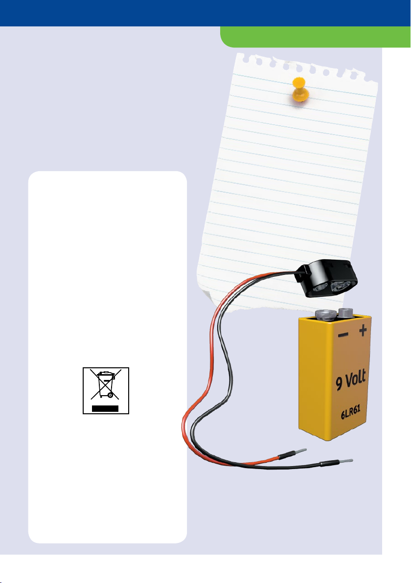
The battery clip will help to conduct
electrical current from the battery to your
circuit. It is easily mounted onto the
battery, with only one orientation being
possible relative to the battery terminals.
The current will then move through the
two loose wires to your circuit.
Battery clip
2.2 MΩ
100 nF
CDS
NTC
GND
+5V...+9V
D0
D1
D2
D3
Digit
BC
EE
n
p
n
BC
EE
p
n
p
10 µF
PWMUin
D0 Din
D1
D2
D3
D4
D5
GND
Beep
Start
Reset
+5V
GND
+9V
B
C
T
E
B
C
E
R
3.3 kΩ
10 k
10 F
C
LED
100 nF
CA
AC
UV
ST
O
P
R
C
Ta
A
CA
+
+
–
9 V
–+
M
–+
NTC
PHT
+ 5V
GND
D0
D1
D2
D3
Dig
IR
PWM
D0
D1
D2
D3
D4
D5
GND
Uin
Din
Beep
Start
Reset
+5V
GND
+9V
Mikrocontroller
CE
CE
+
–
Component Illustration Pictorial Representation Schematic Symbol
Safety note
Never connect the terminals of a
battery directly to each other —
the battery might explode!
Before you can actually start,
there are still a few
preparations you have to take
care of. One is to mount the
contact clips onto your board.
You will also have to insulate
off the wire sections and bend
them into the right shape. The
LEDs will have to be prepared
before inserting them in the
contact clips, too.
Mounting the contact clips
In order to assemble an alarm system or a
lie detector, you will have to be able to
connect the individual components to one
another. That is what the contact clips are
for. These are small, highly conductive
metal parts with holes in the top. You can
insert the components’ terminal wires or
connecting wires (the wire bridges) into
the holes and pull them out again easily.
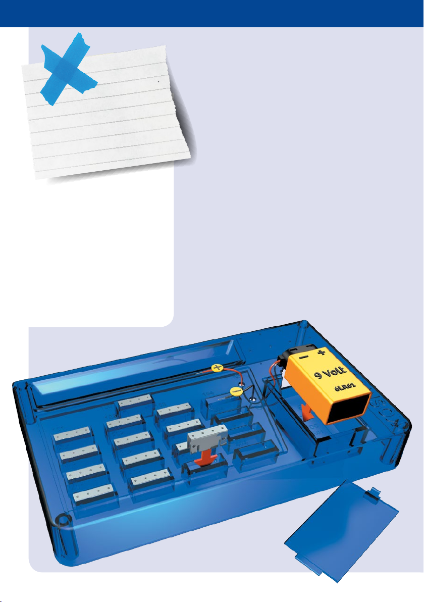
Your kit contains 17 contact clips to insert
into the board. It’s easy. Just hold the sides
of the contact clip between thumb and
forefinger and press them gently together.
Then, simply insert the sides into the
openings. When you insert the clip, be
sure that the side with the holes is always
toward the top. If there are components
that you don’t need right away, you can
keep them in the top compartment and
the recesses to the right. The battery goes
in the compartment next to the area with
the contact clip openings.
Getting ready for
the experiments

EXPERIMENT PREPARATIONS
leaving bare wire ends behind. The two
bare wire end sections should be equally
long, as shown in the picture below. Then,
you will still have to bend the wire pieces
into shape. To do that, place them so they
fit exactly on top of the sketch, and bend
them as shown:
Preparing the wire pieces
Take a careful look at the short and long
wire pieces. You can see that the wire is
surrounded by a thin layer of plastic, know
as “insulation.” The insulation prevents
current from being conveyed to your body,
for example, if you accidentally touch the
wire. There are cuts through the insulation
near both ends of the wire, forming loose
sleeves that you can easily slide off,
Bending the LED terminal wires
You will also have to bend the LED
terminal wires to be able to insert them
into position later on. To do that, proceed
just as you did with the wire bridges: Place
the LED on top of the sketch to the right,
and bend the wires as shown in the
drawing. Please note that one of the LED
terminals is shorter than the other. This
helps to tell them apart, which is
important because the LEDs will only light
up if they are installed in the right
direction.
30 mm 15 mm
15 mm
ACAC
30 mm 15 mm
15 mm
ACAC
30 mm 15 mm
15 mm
ACAC

Insert the transistor module
You always have to install the transistor
correctly, too. All of the assembly drawings
are oriented so the “E” (emitter) terminal
is at the bottom, never at the right, left, or
top.
Getting everything ready
At the beginning of each experiment, you
will find an overview of all the
components that you will need. So start by
looking for all the parts and placing them
in the parts compartment.
The right polarity is important!
Always install the capacitors the right way
around! The assembly drawing shows
exactly how. Also be sure to use the right
capacitance value, 10 µF or 100 µF.
Otherwise, the circuit won’t work right.
Insert the LEDs correctly
The LEDs have one long and one short
terminal wire. The short terminal (the
cathode) is indicated with a “C” in the
drawings, and the longer one (the anode)
is indicated with an “A.” In addition, the
cathode side of the LED is flattened.
C
TIPS AND TRICKS
Pay attention to the wire colors
The current always has to flow in the right
direction. It can only do that if you attach
the battery terminal wires correctly.
The positive wire coming from the battery
clip is red, while the negative wire is black.
The same colors are used in the assembly
drawing as well.
In the drawing, you will also see a +and a
–sign next to the connections.
Using the right resistors
The resistors protect components such as
the LEDs against excessive current, which
might destroy them. So always be sure to
install the right ones.

The circuit diagram
In order to understand how a circuit
works, you need a circuit diagram. It uses
symbols to represent the individual
components and shows how they are
connected to one another.
You can check the meanings of the
symbols by taking a look at the section
with the component descriptions. This
kind of schematic circuit diagram is much
easier and quicker to draw than a
complete circuit board illustration. For
each experiment, you will find both a
pictorial illustration as well as its
corresponding circuit diagram.
As an example, this is the circuit diagram
for a battery tester (Experiment 18).
+
–
9V
T1
R 4
470 Ω
R 3
470 Ω
R 1
220 kΩ
R 2
22 kΩ
LED 1

The circuit board illustration
If you have a complicated circuit assembly,
a schematic circuit diagram can be quite
difficult for a layperson to understand.
That is why, in some of the experiments,
we also illustrate the board as viewed
straight down from above.
In these illustrations, all of the
components are shown and labeled
exactly as described on pages 2 to 8. So if
you ever aren’t sure exactly which
component you are supposed to use, you
can check the front of this manual.
This shows the illustration corresponding
to the battery tester (Experiment 18)
circuit board on the previous page.
Note!
The colors of the components can
sometimes be different from how
they are shown in the manual
illustrations. This will not affect
their function.
TIPS AND TRICKS

Conductance
Would you like to know which things are good conductors
of electricity and which are not? Then assemble your
humidity detector and start by testing the conductance of
water.
Conductance
EXPERIMENT
Humidity detector
YOU WILL NEED
resistors, Ω
resistor, . kΩ
resistor, kΩ
resistor, kΩ
resistor, kΩ
short wire bridges
long wire
connectors
LEDs
transistor modules
electronics board
battery clip
+ and additional household
items: 9-volt square battery,
glass of water
+
–
9V
T2
T1
R 5
3.3 kΩ
R 2
100 kΩ
R 6
470 Ω
R 4
22 kΩ
LED 2
LED 1
R 3
470 Ω
R 1
220 kΩ
A
B
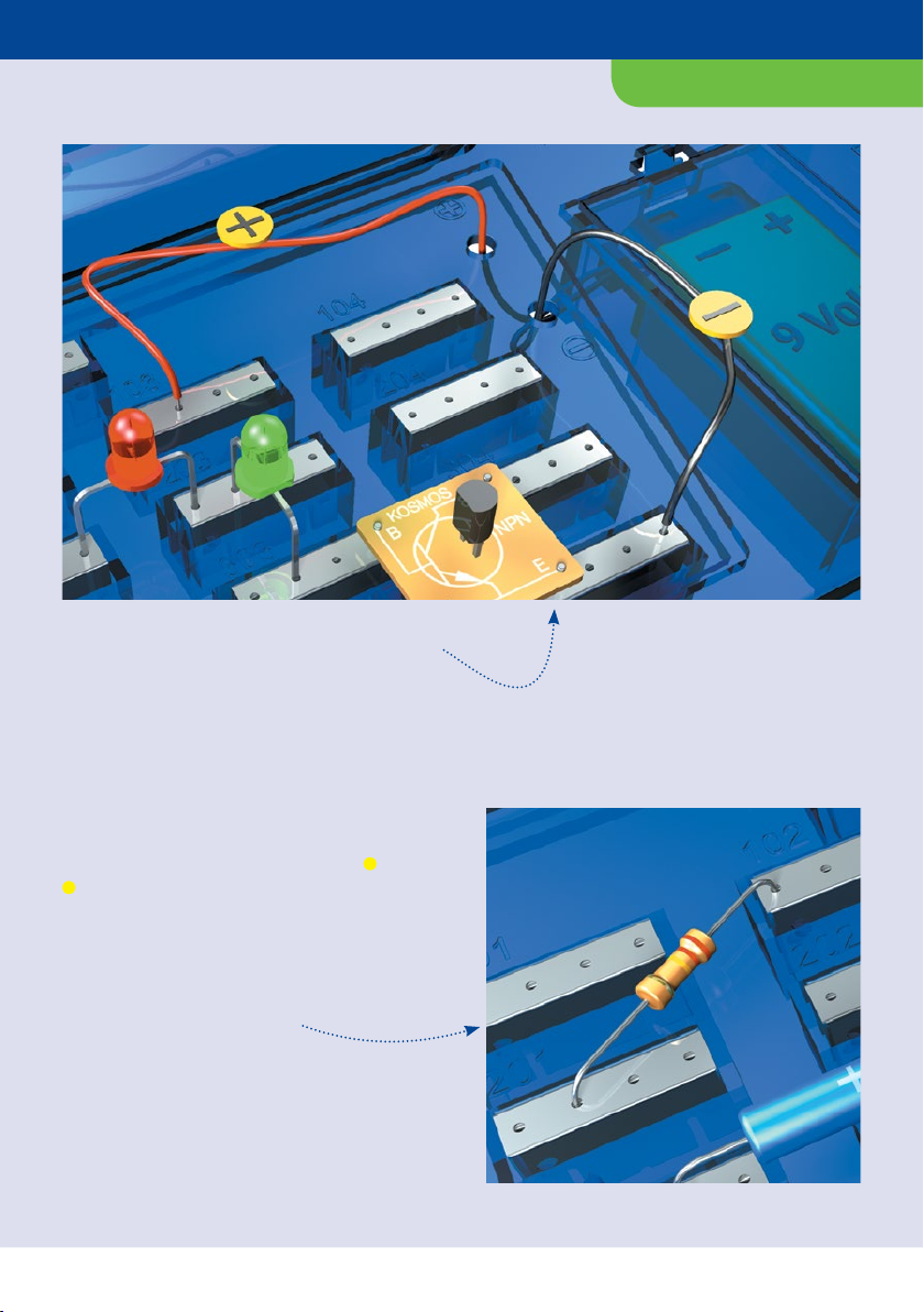
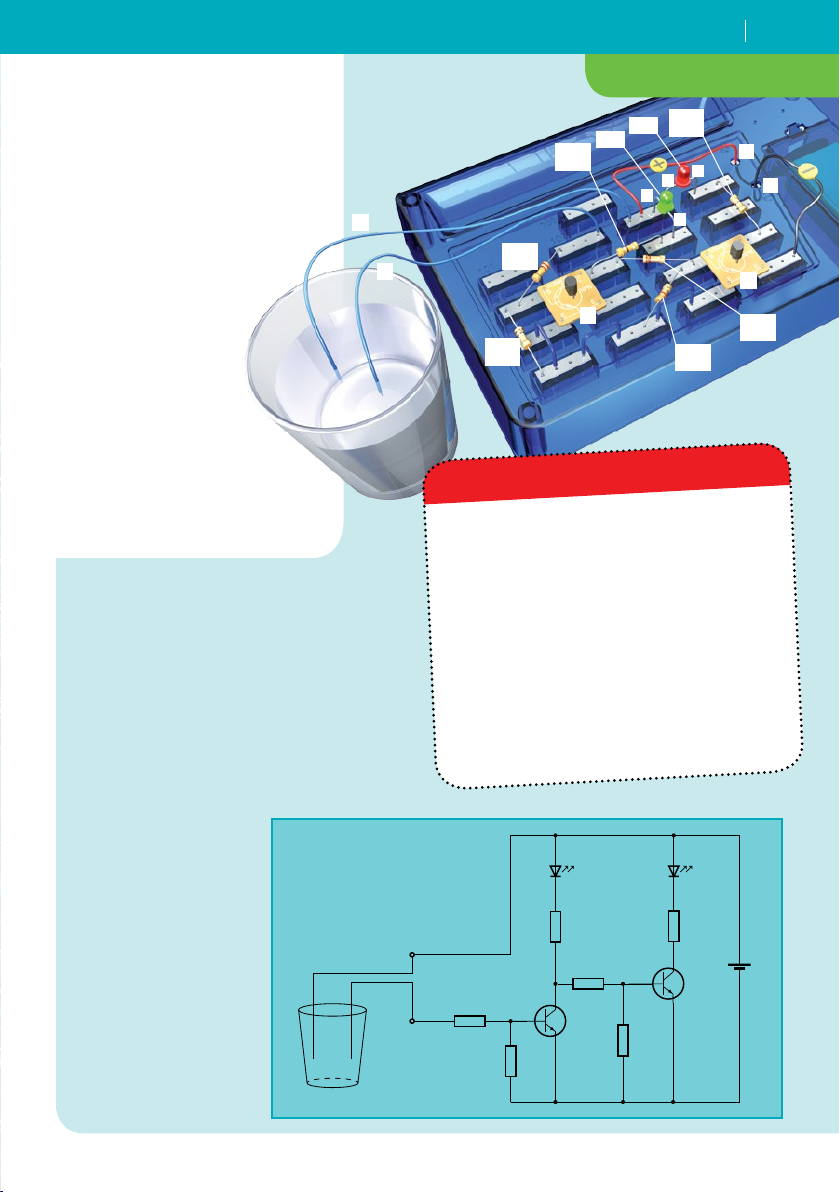
HERE’S HOW
1. Assemble the circuit following the
circuit diagram. You will use the
loose ends of the two long wires
(“A” and “B”) as “sensors.”
2. Fill a glass with tap water.
3. Dangle the two long wires A and B
into the glass.
What happens?
4. Now pull the
wires back out of
the glass.
5. Hang the two
wires in the water
again and wait a
couple days.
What happens
when the water
evaporates?
As soon as the two long wires touch the
water, the green LED lights up — an
indication that there’s enough water
present. If you pull one of the wires out
of the glass, the green LED will go out
and the red one will come on. The same
thing happens, of course, when the
water level drops far enough in the glass
for the wires to be no longer covered
with water. The red LED turns on, in
other words, when there’s not enough
water!
WHAT’S HAPPENING?
R1
KΩ
R5
. KΩ
R4
KΩ
R6
Ω
LED2
LED1
T1
A
+
–
BT2
AC
A
C
R3
Ω
R2
KΩ
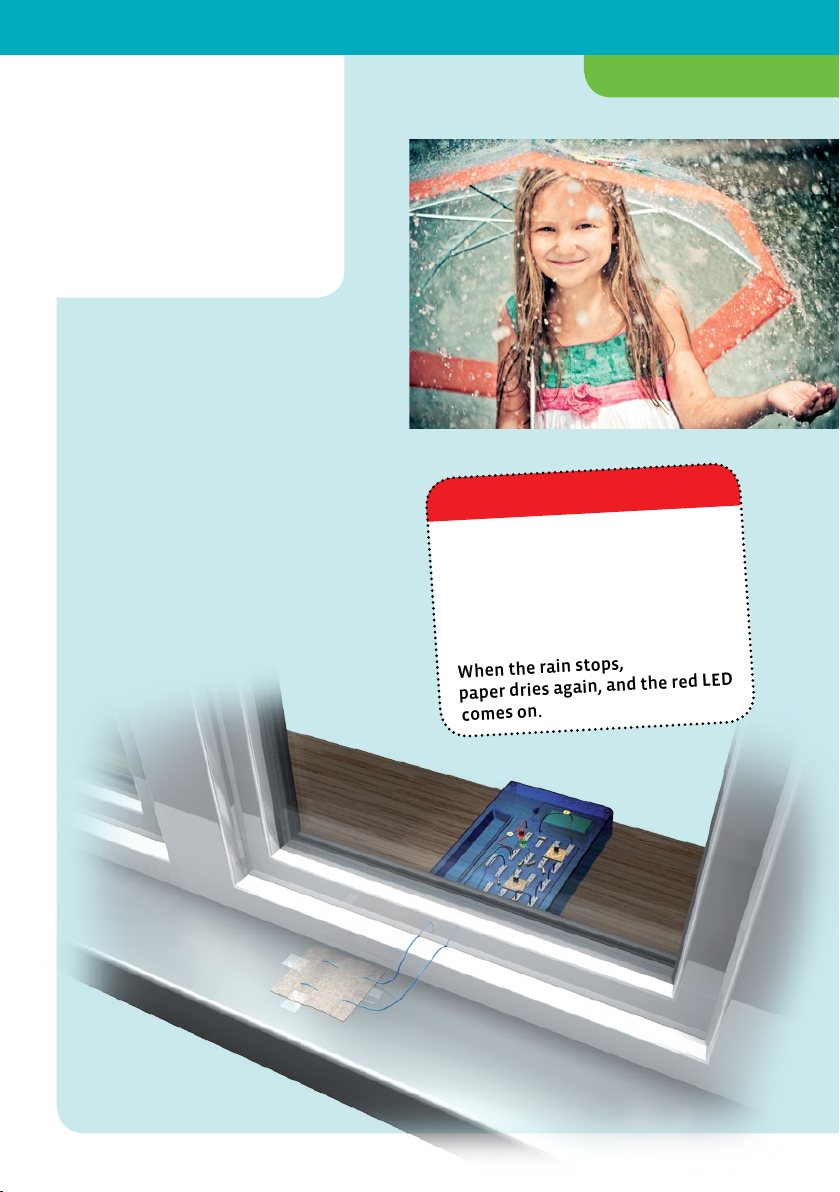
Rain sensor
YOU WILL NEED
your humidity detector
+ and additional household
items: blotting paper, tape,
scissors
HERE’S HOW
1. Cut a piece of blotting paper about
5 x 10 cm in size and tape it to the
outside sill of a window in your
room.
2. Insert the bare ends of the long
wires A and B of the humidity
detector into the blotting paper
strip. Now you just have to wait for
a good rain.
When it starts to rain, the blotting
paper soaks up water and your
electronic circuit reacts to the
moisture — the green LED
lights up.
When the rain stops, the blotting
paper dries again, and the red LED
comes on.
WHAT’S HAPPENING?
EXPERIMENT
Table of contents
Other Thames & Kosmos Science Education Product manuals


