Thames & Kosmos PHYSICS pro User manual
Franckh-Kosmos Verlags-GmbH & Co. KG, Pfizerstr. 5-7, 70184 Stuttgart, Germany | +49 (0) 711 2191-0 | www.kosmos.de
Thames & Kosmos, 301 Friendship St., Providence, RI, 02903, USA | 1-800-587-2872 | www.thamesandkosmos.com
Thames & Kosmos UK Ltd, Goudhurst, Kent, TN17 2QZ, United Kingdom | 01580 212000 | www.thamesandkosmos.co.uk
EXPERIMENT MANUAL
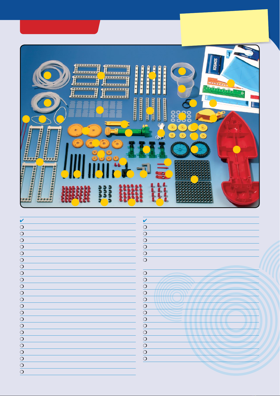
KIT CONTENTS
3
The parts in your kit:
30
44
411211
33
38
1
39
6
21
26
40
18
17
16
10
9
7
32 25
23
8
No. Description Count Item No.
1 Anchor pin 40 702527
2 Joint pin 12 702524
3 Shaft plug 30 702525
4 Shaft pin 2 702526
5 Axle lock 12 702813
6 Washer 12 703242
7 Long frame 4 703239
8 Short frame 6 703232
9 Long rod 6 703235
10 Short rod 6 703233
11 Long axle 4 703234
12 Medium axle 5 703238
13 Short axle 1 703236
14 Medium pulley wheel 4 702518
15 Small pulley wheel 4 702519
16 Large gear wheel (60 teeth) 2 702506
17 Medium gear wheel (40 teeth) 4 702505
18 Small gear wheel (20 teeth) 7 702504
19 Baseplate 2 703237
20 Crankshaft 2 702599
21 XL (extra long) axle 1 703518
22 Connector bridge 2 703231
23 Turbine blade 16 702815
43
24
36
35
29 37
14
15
28
19
13 31 22
420
42
5 3 2
No. Description Count Item No.
24 Rubber band (long) 1 703241
25 Rubber band (medium) 1 703374
26 Cotton cord (white) 1 703244
28 Wheel 2 703230
29 Tire ring (medium pulley wheel) 2 703251
30 Anchor pin lever 1 702590
(Part separator tool)
31 Crank 2 703377
32 Straw (red) 2 703513
33 Digging shovel 1 703514
34 Experiment book (not shown) 1 703510
35 Measuring cup 1 703532
36 Plastic strip for spring motor 1 703240
37 Film for cutouts 1 703380
38 Boat hull 1 703519
39 Die-cut cardboard sheets 1 703522
40 Hydraulic pump 1 703515
41 Hydraulic switch 1 703516
42 Hydraulic cylinder 4 703378
43 Narrow tubing 1 703500
44 Thick tubing 1 703511
GOOD TO KNOW! If you are missing any
parts, please contact Thames & Kosmos
customer service. Any materials not included
in the kit are indicated in italic script under
the “You will need” heading.
39
21
20
19 22
23
24
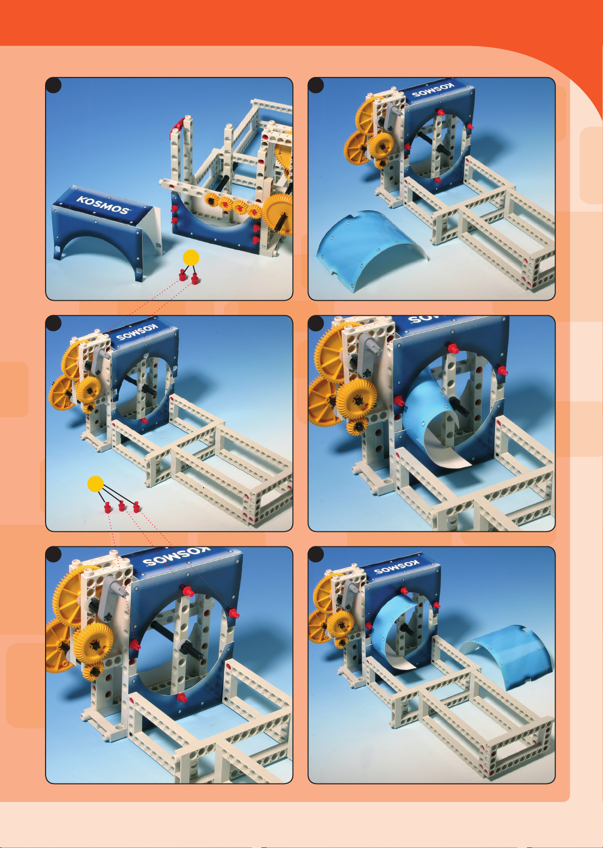
Air and Water in the Flow
3
3
Physics Pro 2014 Part 1.indd 39 8/1/14 1:27 PM
GOOD TO KNOW
45
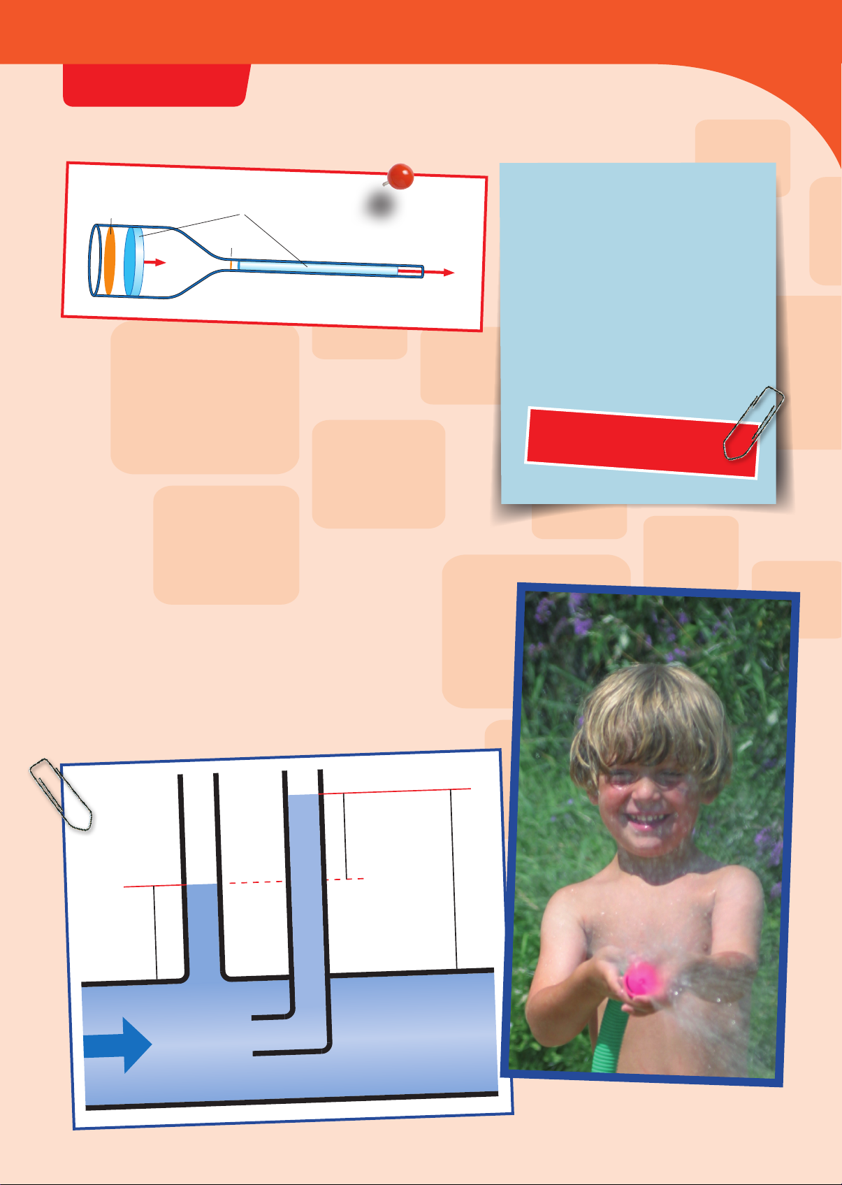
Air and Water in the Flow
The pressure in the direction of
flow is also called dynamic
pressure, because it arises with
dynamics, or the force of
movement. In tubes, there is
always also something called
static (resting) pressure, which is
a product of the difference in
pressure between the entrance to
and exit from the tube.
Dynamic pressure is measured
against the stream, static
pressure in the stream. When the
liquid is resting, there is only
static pressure, and the dynamic
pressure is equal to zero. When
movement starts, dynamic
pressure rises and static pressure
simultaneously drops.
That also applies in reverse. In a
uniform current, in any case, the
sum of the two pressures is
always the same.
Because the speed of the water increases in the narrow part of a tube,
the pressure also increases in the direction of flow. But an increase in
pressure also means an increase in force per unit of area and, thus, an
increase in the distance the narrower stream of water can shoot.
Pressure in currents
THE FLOW EQUATION
If you multiply the large cross-
sectional area (A1) by the
corresponding velocity (v1), the
product is the same as when you
multiply the small cross-sectional
area (A2) by the velocity there (v2).
This equation is called the flow rate
equation or continuity equation:
1 N =1 kg · m
s
2
1 Pa =
1 bar = 1,000 hPa
1 N
1 m
2
1 W =1 J
1 s
P (Pressure) =
F1: A1= F2: A2
p1: p2= V2: V1
p1: p2= T1: T2
or: p · V = constant
(only valid when T = constant)
F1· L1= F2· L2
p1· V1= p2· V2
A1· v1= A2· v2
Load · Load arm = Force · Force arm
F (Force)
A (Area)
P (power) =
W (work) = F (force) · s (distance)
W (work)
t (time)
Fd=C
d· A · · v
2
2
P ==2=2 Pa
10 N
5 m
2
N
m
2
P ==200,000 Pa
100 N
0.0005 m
2
P =
= 16,000 Pa or 16 hPa or 1.6 bar
4 N
0.00025 m
2
or = constant=
p1· V1
T1
p · V
T
p2· V2
T2
Fd= 0.4 ·2 m
2
· 1.23 kg/m
3
· (40 m/s)
2
2
Fd= 0.4 ·=787.2 N
3936
2
kg · m
s
2
Total energy
Work yielded
Friction
Slip-
stream Turbulence
Panel
Cylinder
Teardrop
Turbulence
Toggle switch center
Stop in all directions
Supply
Toggle switch
left
Toggle switch
right
Total Pressure
Dynamic
Pressure
Static Pressure
F1
F2
F2
L1
L2
F1
L1
L2
One-armed
lever
Two-armed
lever
Lift
Aileron
(wing flap)
Rudder
Pitch elevator
Horizontal stabilizer
Stagnation point
Lift through low pressure on the
upper side of the wing
Vertical stabilizer
(vertical tailfin)
Wing
Aileron (wing flap)
Gravity
Wing
Center of
mass
Center of lift
Stagnation point while gliding
A1
V1 V2
Equal quantities of water
A2
H1
H2
Buoyancy B =
Hydrostatic pressure 1 –
Hydrostatic pressure 2
B
Stagnation point
Lift through low pressure on the
upper side of the wing
Additional lift through pressure
on the underside
Pressure on the underside
Total energy
Work yielded
Friction
Slip-
stream Turbulence Panel
Cylinder
Teardrop
Turbulence
Toggle switch center
Stop in all directions
Supply
Toggle switch
left
Toggle switch
right
Total Pressure
Dynamic
Pressure
Static Pressure
F1
F2
F2
L1
L2
F1
L1
L2
One-armed
lever
Two-armed
lever
Lift
Aileron
(wing flap)
Rudder
Pitch elevator
Horizontal stabilizer
Stagnation point
Lift through low pressure on the
upper side of the wing
Vertical stabilizer
(vertical tailfin)
Wing
Aileron (wing flap)
Gravity
Wing
Center of
mass
Center of lift
Stagnation point while gliding
A1
V1 V2
Equal quantities of water
A2
H1
H2
Buoyancy B =
Hydrostatic pressure 1 –
Hydrostatic pressure 2
B
Stagnation point
Lift through low pressure on the
upper side of the wing
Additional lift through pressure
on the underside
Pressure on the underside
Physics Pro 2014 Part 1.indd 45 8/1/14 1:27 PM
1
2
3
x 23
17
19
6
5
11
8
17
Compressed air
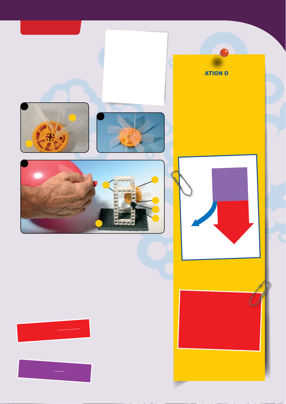
EXPERIMENT 18
YOU WILL NEED
› Axle lock
› Washer
› Short frames
› Long axle
› Medium gear wheels
› Baseplate
› Turbine blades
› 1 Balloon
The air-filled balloon has potential
energy too. You can drive a paddle
wheel turbine with it.
CONSERVATION OF ENERGY
Not all of the potential energy of the
water is converted into hammer beats in
our gravity hammer experiment. Part of
it is used up by friction in the axle seats,
the pulley wheels, and the hammer
shaft. In this process, it is only lost as far
as the hammering is concerned. If you
add up the work from the friction and
the hammering, it equals the energy you
started with.
In other words, the conservation of
energy law applies:
Total energy
Work yielded
Friction
Slip-
stream Turbulence Panel
Cylinder
Teardrop
Turbulence
Toggle switch center
Stop in all directions
Supply
Toggle switch
left
Toggle switch
right
Total Pressure
Dynamic
Pressure
Static Pressure
F1
F2
F2
L1
L2
F1
L1
L2
One-armed
lever
Two-armed
lever
Lift
Aileron
(wing flap)
Rudder
Pitch elevator
Horizontal stabilizer
Stagnation point
Lift through low pressure on the
upper side of the wing
Vertical stabilizer
(vertical tailfin)
Wing
Aileron (wing flap)
Gravity
Wing
Center of
mass
Center of lift
Stagnation point while gliding
A1
V1 V2
Equal quantities of water
A2
H1
H2
Buoyancy B =
Hydrostatic pressure 1 –
Hydrostatic pressure 2
B
Stagnation point
Lift through low pressure on the
upper side of the wing
Additional lift through pressure
on the underside
Pressure on the underside
Balloon
In a closed mechanical
system, no energy is lost.
Energy can be neither created
nor destroyed. It can only be
converted. The sum of the
mechanical energy remains
the same (constant).
When you calculate power, time
becomes a factor. Power is the
relationship of the work
performed to the time needed to
do it:
In addition to watts, kilowatts (1
kW = 1,000 W) and megawatts (1
mW = 1,000,000 W) are also used
as units of power. The engine of a
mid-sized car handles about 60
kW. A human can perform about
200 watts of physical work over
a long period of time, while a
cyclist with a bicycle can get to
1,500 watts fairly quickly.
Work is measured independent of the time it takes to do the work. If
you do the same amount of work in less time, then you exert more
power doing it — whether its raising your hand in school or biking.
Power is work divided by time
1 N =1 kg · m
s
2
1 Pa =
1 bar = 1,000 hPa
1 N
1 m
2
1 W =1 J
1 s
P (Pressure) =
F1: A1= F2: A2
p1: p2= V2: V1
p1: p2= T1: T2
or: p · V = constant
(only valid when T = constant)
F1· L1= F2· L2
p1· V1= p2· V2
A1· v1= A2· v2
Load · Load arm = Force · Force arm
F (Force)
A (Area)
P (power) =
W (work) = F (force) · s (distance)
W (work)
t (time)
Fd=C
d· A · · v
2
2
P ==2=2 Pa
10 N
5 m
2
N
m
2
P ==200,000 Pa
100 N
0.0005 m
2
P =
= 16,000 Pa or 16 hPa or 1.6 bar
4 N
0.00025 m
2
or = constant=
p1· V1
T1
p · V
T
p2· V2
T2
Fd= 0.4 ·2 m
2
· 1.23 kg/m
3
· (40 m/s)
2
2
Fd= 0.4 ·=787.2 N
3936
2
kg · m
s
2
The unit of measure for power P
is the watt (W):
Water, Air, and Energy
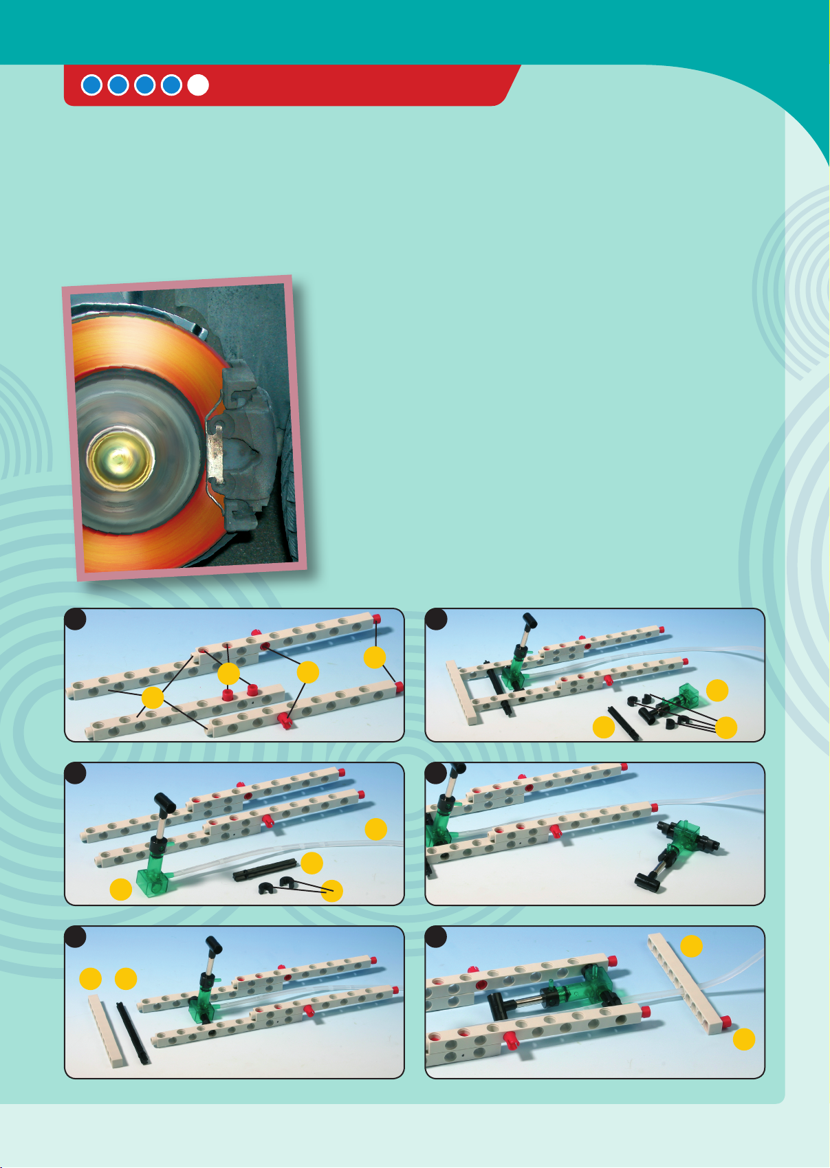
CAR WITH HYDRAULIC BRAKES
Every vehicle should be able to brake. As
their main braking device, passenger cars
have a hydraulically activated foot brake.
Its hydraulic mechanism consists of a
cylinder that transfers force from the
YOU WILL NEED
› 8 Anchor pins 1
› 4 Joint pins 2
› 2 Shaft plugs 3
› 10 Axle locks 5
› 8 Washers 6
› 1 Short frame 8
› 4 Long rods 9
› 6 Short rods 10
› 4 Long axles 11
› 3 Medium axles 12
› 2 Medium pulleys 14
› 2 Large gear wheels 16
› 2 Small gear wheels 18
› 1 XL (extra long) axle 21
› 1 Rubber band (medium) 25
› 2 Wheels 28
› 2 Tire rings for pulleys 29
› 2 Hydraulic cylinders 42
› 1 Piece of narrow tubing 43
brake pedal to the main cylinder. From
there, the braking force is transferred
equally by separate pathways to the
braking cylinders on the wheels. Big and
heavy vehicles, e.g. a tour bus or dredger,
have so-called servo brakes, which
amplify the braking force through a
pump.
This model is like the racing car model
(page 89) — but without the drive spring.
Test the hydraulic brake by pushing
against the car’s brake pedal (the front
pair of rods). Push the pedal down to
activate the brake. That pulls the rear pair
of rods down onto the tires. Water will
serve as the hydraulic fluid. You will see
in Experiments 1 and 2 (on pages 10 and
11) how to fill it without air bubbles.
>See Pages 10-11 and 20-22
4
10
1
2
1
1
9
12
42
42
12
43
5
10 11
1
2
3
5
6
5
Let‘s Build Models
65
Physics Pro 2014 Part 2.indd 65 8/1/14 1:24 PM
Other Thames & Kosmos Science Education Product manuals


