Tips and Tricks for
Model Building and Experiments
Frames (2, 3) and rods (4, 5) are
connected to each other with the help
of the anchor pins (26).
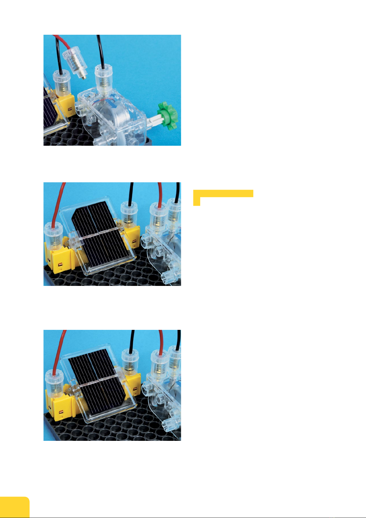
The short end of the axle
shaft (16, 17, 18) is built
so that the shaft can’t
slip through a hole.
If wheels or pulleys are
mounted too close to
other components, it is
hard to turn them.
If a wheel is mounted too
tightly on an axle shaft,
you can push out the axle
shaft with another.
If wheels have enough
“play,” they turn easily.
short end
long end
Follow the Instructions Closely
With this experiment kit, you will assemble a variety of
solar models and conduct a lot of experiments. It is best to
assemble the models in order. Then, it will be easier for you
to construct the complicated models at the end. For all the
models, it is important that all the individual components
are put together properly. Only then will everything work
right. To help you with this, there is a picture correspond-
ing to every step in the assembly process. The instructions
that go with the picture tell you exactly which pieces to use.
Following each piece mentioned in the instructions, there is
a number in parentheses. This is the number that you will
find in the overview of the kit contents on pages 2-3. So if
you aren’t quite sure which piece you are supposed to be
using, you can check on pages 2-3 to verify exactly which
piece it is.
About Connecting Frames and Rods
The basic construction of all of
the models consists of frames
and rods, which are connected
to each other with the help of
anchor pins. Some anchor pins
are already permanently mounted
to all of the frames and rods. But
for most of the connections, you
will need the red anchor pins
(26). They are simply inserted
into the holes of the frames and
rods and serve to ensure a secure
assembly.
To make it easier to remove
the anchor pins from the holes,
your kit comes with a small tool,
the anchor pin lever (30). It has
two different sides, marked “A”
and “B.” The narrow side with the
“A” serves to lever out the anchor
pins. The other side, marked with
the “B,” is wider. You can use it to
remove shaft plugs (25) from the
frames or rods.
You can use the narrow side of the
anchor pin lever (30) to pull the
anchor pin (26) out again.
With the help of the shaft plugs (25),
you can mount individual gear wheels or
sprocket wheels to frames or rods.
The shaft plugs can be levered out with
the broad side of the anchor pin lever.
About Wheels and Pulleys
In this box of solar experiments, you
will find four types of wheels: gear
wheels (6, 7, 8), sprocket wheels (9, 10,
11), pulley wheels (12, 13, 14), and tire
wheels (15). They all perform different
functions.
Gear and sprocket wheels are used
in all of the models. They have two
functions: first, they serve to transfer
the rotary motion of the solar engine
to other components. Second, they
are used to secure axles (16, 17, 18, 19)
so that they don’t slip. The tire wheels
are used to transfer the power of a
vehicle’s engine to the ground surface.
The pulley wheels serve to guide the
cord. In most cases, wheels and pulleys
are secured with the help of the axle
shafts (16, 17, 18). You can also attach
wheels and pulleys to the engine shaft
(19) or secure them individually with
the small red shaft plugs (25).
About Mounting Wheels
The axle shafts (16, 17, 18) and the en-
gine shaft (19) each have two different
ends: one short and one long. On the
short end, wheels and pulleys can only
be pushed on a little way. But if you
push them onto the long end, you can
position wheels and pulleys wherever
you want on the shaft.
The short end is constructed in
such a way that the axle shaft can’t slip
through a hole. To secure an axle shaft
to a rod or frame, it will suffice to push
a wheel, sprocket, or gear onto the
long end to serve as a bracket. When
building a model, you have to pay close
attention to which direction an axle
shaft is inserted.
With all of the models, wheels and
pulleys have to be able to rotate freely.
Otherwise, the solar engine won’t be
able to turn them. For that reason, it is
very important that wheels and pulleys
have enough “play” — as the profes-
sionals call it — and not be mounted
too close to other components. So
always leave a little room between a
wheel or pulley and other components.
Then, everything will go smoothly.
Sometimes, it may be difficult to
remove a wheel from its axle. If that
happens, use another axle shaft as a
tool; hold the wheel tight and push
with the other axle shaft against the
axle that the wheel is mounted on (see
picture at right).
4